1
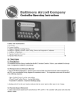
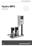
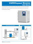
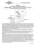
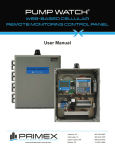
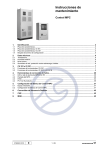
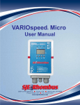
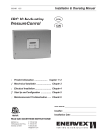
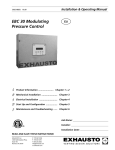
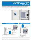
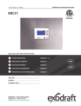
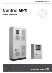
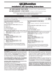
VFDC-4000 Controller
Variable Frequency Drive Controller
User Manual
This manual explains the features and operations of the VFDC-4000 controller which is specifically designed for Pressure Booster Pump Systems. The
VFDC-4000 controller is capable of maintaining a constant discharge pressure by adjusting the speed of 1 to 4 Variable Frequency Drives (VFDs).
www.sjerhombus.com
WARNINGS
Failure to read and understand the information provided in this manual may result in personal injury or death, damage to
the product or product failure. Please read each section in its entirety and be sure you understand the information provided in the section and related sections before attempting any of the procedures or operations given.
Failure to follow these precautions could result in serious injury or death.
Keep these instructions with warranty after installation. This product must be
installed in accordance with National Electrical Code, ANSI/NFPA 70 so as to
prevent moisture from entering or accumulating within the controller housing.
ELECTRICAL SHOCK HAZARD
Disconnect power before installing or servicing this product.
A qualified service person must install and service this product
according to applicable electrical codes and electrical schematics.
•
Do not install in area with: excessive or conductive dust, corrosive or
flammable gas, moisture or rain, excessive heat, regular impact shocks
or excessive vibration.
•
Do not place in water or let water leak onto the controller.
•
Do not allow debris to fall inside the unit during installation.
•
Double-check all the wiring before turning on the power supply.
•
Do not touch live wires.
•
Stay as far as possible from high-voltage cables and power equipment.
•
Leave a minimum of 10 mm space for ventilation between the top and
bottom edges of the controller and enclosure walls.
EXPLOSION OR FIRE HAZARD
Do not use this product with flammable liquids. Do not install in
hazardous locations as defined by National Electrical Code,
ANSI/NFPA 70.
Table of Contents
Chapter 1
1.1 Controller Description . . . . . . . . . . . . . . . . . . . . . . . . . . . . . . . . . . . .2
1.2 Controller Outline Dimension . . . . . . . . . . . . . . . . . . . . . . . . . . . . . .3
Chapter 2
2.1 Description of Each Function . . . . . . . . . . . . . . . . . . . . . . . . . . . . . .4
2.2 Definitions . . . . . . . . . . . . . . . . . . . . . . . . . . . . . . . . . . . . . . . . . . . . .6
2.3 Default Values . . . . . . . . . . . . . . . . . . . . . . . . . . . . . . . . . . . . . . . . . .7
2.4 Key & Icon Description . . . . . . . . . . . . . . . . . . . . . . . . . . . . . . . . . . .9
2.5 Description of LCD Screen . . . . . . . . . . . . . . . . . . . . . . . . . . . . . . .10
Chapter 3
3.1 Security . . . . . . . . . . . . . . . . . . . . . . . . . . . . . . . . . . . . . . . . . . . . . .11
3.2 Setup Menus . . . . . . . . . . . . . . . . . . . . . . . . . . . . . . . . . . . . . . . . . .11
3.3 Setup Menu Display & Input Method . . . . . . . . . . . . . . . . . . . . . . .14
Chapter 4
4.1 Terminal Connection Connections . . . . . . . . . . . . . . . . . . . . . . . . . .16
4.2 Controller Circuit Diagram of Communication Operation . . . . . . . .17
Chapter 5
5.1 Troubleshooting . . . . . . . . . . . . . . . . . . . . . . . . . . . . . . . . . . . . . . . .18
Chapter 6
6.1 Fault Alarm Display & Corrective Actions . . . . . . . . . . . . . . . . . . . .19
6.2 Alarm Data Log . . . . . . . . . . . . . . . . . . . . . . . . . . . . . . . . . . . . . . . .20
6.3 Operation Data Log . . . . . . . . . . . . . . . . . . . . . . . . . . . . . . . . . . . . .20
ModBus Communication Functions & Adress Code . . . . . . . . . . . .22
Serial Cable for RS232 Communication . . . . . . . . . . . . . . . . . . . . . . .24
SJE-Rhombus VFDC-4000 Controller User Manual
1
Chapter 1
1.1 Controller Description
<Front View>
LCD Screen
LED Indicators
Push Button
<Rear View>
CN10 RS485 Port
CN2 Sensor Terminal
CN8 Buzzer
Stop/Manual/Auto/Low Water
CN1 VFD DA
Output Terminal
CN3 VFD
Output Terminal
CN7 VFD Fault
Input Terminal
CN5 Sub
Relay Terminal
CN4 DC Power
Supply Terminal
2
SJE-Rhombus VFDC-4000 Controller User Manual
1.2 Controller Outline Dimensions in inches.
SJE-Rhombus VFDC-4000 Controller User Manual
3
Chapter 2
2.1 Function Description
LSC Display
The LSC Display is a user friendly operator interface with 240 x 64 dots resolution; it allows the user to quickly view the
system status and log.
Multiple Pumps Parallel Operation
The controller is able to control up to 4 VFD’s and may be used for large volume booster pumping systems.
Lead/Lag Operation
A fully automatic lead/lag operation based on the variation of the system discharge flow allows you to significantly reduce
your energy cost and consistently maintain the system piping pressure. While the lead pump is operating, the system
will sequentially start and stop lag pump(s) based on variation of the system pressure.
Automatic Re-Start
Should the system shutdown by a sudden power loss, it will automatically restart when the power is restored. No manual
reset is required. The system automatically returns to the running condition programmed and stored in the system memory.
Lead Pump Alternation
When selected as set time based, the alternation will occur when the total operating time of the lead pump reaches the
alternation time; the system automatically selects the next pump in sequence to be the lead pump. This function is
designed to reduce the system life cycle cost. The system makes all pumps operate for an equal period of time to prevent the over-use of a particular pump resulting in high parts wear of the pump. The alternation may also be cycle based
rather than time based.
Faulty Pump(s) Skip Function
The system automatically detects faulty pump(s) and they will not be part of the operation sequence.
Dry Run Prevention
The system stops the running pump(s) upon detecting a low water level or low suction pressure signal. This prevents
the pump(s) from dry running which may result in damage to the pump(s).
Operation Schedule
It is possible to program the set pressure based on a time/day/month basis.
Alarm Display and Logging
The system displays alarm conditions on the LCD monitor, and records the condition in a log that is date and timed
stamped.
Operating Data Display and Storage
The semi-permanent operating data recording and storage for each pump allows efficient pump maintenance.
Freeze Prevention
The lead pump is automatically started (VFD minimum output) for 30 seconds and then shifted to the next pump when
the temperature is under 32oF. This will occur when all pumps are stopped for more than 30 seconds at the same time.
Idle Prevention
If a lead pump does not run for a certain period of time, corrosion of some parts may occur. In order to prevent this, the
system will automatically run the lead pump at the minimum operating speed for 60 seconds and then starts the next
pump in sequence. The same process will be repeated if the succeeding lead pump does not run during the set time.
4
SJE-Rhombus VFDC-4000 Controller User Manual
Password
If the password function is enabled, a User Password pop-up window will appear when you press the MENU button. You
must enter your password to access the setup screens. This is to prevent access to the input values by any unauthorized person in advance. You can change or disable the user password if you wish. Each system has its own master
password. Should you lose your password, call us to obtain a master password.
PID Control
This microprocessor-based controller is programmed to perform Proportional, Integral and Derivative control to provide
consistent and reliable pressure control.
LCD Screen Saver
The back light of the LCD display is programmed to automatically fade out if the keypad is not used for a set time. This
function allows for maximum life span of the LCD monitor.
Self-Diagnosis
They system includes a built-in self-diagnosis program that continuously monitors various system operating conditions.
Night Pump Operation
You can select Night-Pump (smaller pump) mode program to operate pumps with smaller capacity for night time. (Night
pump is typically the smaller capacity pump).
SJE-Rhombus VFDC-4000 Controller User Manual
5
2.2 Definitions
Menu Screen Items: Follow the menus on the main screen.
NOTE: A password may be required to access the Menu screens.
6
NO
Menu
Functions
Details
1
DATE
TIME
Year/Month/Date/Week/Hour/Minute/Second Input
Set Year, Month, Date, Week, and Hour.
2
PUMP
SET UP
Setting up the number of pumps to run in the
sequence. Setting up the Night time pump.
Select a lead pump, the number of pumps to run.
Select Night-pump mode.
3
PRESSURE
SET UP
Adjust the set pressure & High/Low limit pressure/
Lag Run/Stop pressure setting.
Set the Set/High/Low/Lag Run/Stop pressure.
4
CONTROL
SET UP
P/I/D value, Cycle Time, Shift, Friction, Run & Stop
Delay, Operation Type, Low Water & Low Pressure
Stop Time and Initialize.
Sets the control values.
5
SENSOR
SET UP
Transducer Type/Sensor Adjusting Setting.
Select the used Pressure Sensor Range.
Zero + Span + Offset adjustment.
6
VFD
SET UP
VFD Stop Time, VFD Minimum Rate (speed), VFD
Stop Time, VFD Output Display Type and VFD
Auto Reset.
Set the type of Output Display for the VFD, stop
time, minimum output, start rate and stop rate.
7
PROTECTION
Freeze prevention, Idle prevention and Password.
Automatically pump runs in case of pump stops for
a set period of time with a temperature below 32oF
for 2 minutes.
8
SYSTEM
SET UP
Return to the Main Menu, LCD Back Light Time,
Data Backup Interval, Test Code, Relay 1˜4.
LCD screen return time, Back Light Display time,
etc.
9
OPERATION
SCHEDULE
Operation Schedule Mode selection
(Time/Day/Month)
Operation Schedule (Time/Day/Month) setting.
10
COMMUNICATION
SET UP
When using the communication feature.
Set Communication type, Set Speed, and
Address Code.
11
ALARMS
Alarm data log.
Display the error information such as High/Low
pressure limit alarm, water shortage alarm, VFD
fault alarm. You can see the date and time when
they occurred.
12
DATA LOG/
RUN TIMES
Data log for pump operation
Time & date stamps for run cycles and hour meter
for each pump.
SJE-Rhombus VFDC-4000 Controller User Manual
2.3 Default Values
Menus
Setup Menus
Default
Input Range
YEAR
MONTH
DATE
WEEK
HOUR
MINUTE
SECOND
2000
1
1
SUN
0
0
0
0000 ~ 9999
1 ~ 12
1 ~ 31
MONDAY ~ SUNDAY
0 ~ 23
0 ~ 59
0 ~ 59
LEAD PUMP
PUMP 1
PUMP 2
PUMP 3
PUMP 4
NIGHT TIME
PUMP 1
USED
USED
NOT USED
NOT USED
00:00 ~ 04:00
1~4
USED, NOT USED
USED, NOT USED
USED, NOT USED
USED, NOT USED, NIGHT PUMP
00:00 ~ 23:59
SET PRESSURE
HIGH PRESSURE LIMIT
LOW PRESSURE LIMIT
START LEAD PRESSURE
START LAG PRESSURE
STOP LAG PRESSURE
60 PSI
95 PSI
15 PSI
-3 PSI
-7 PSI
3 PSI
2 PSI ~ 650 PSI
3 PSI ~ 719 PSI
1 PSI ~ 649 PSI
-65 PSI ~ 65 PSI
-65 PSI ~ 65 PSI
0 PSI ~ 65 PSI
P
I
60
30
0 ~ 200
0 ~ 200
CONTROL
SET UP
D
CYCLE TIME (PID)
ALTERNATION
FRICTION
RUN DELAY
STOP DELAY
OPERATION TYPE
LOW WATER STOP TIME
LOW PRESSURE STOP TIME
INITIALIZE
1
120
24 HOURS
0.0 PSI
0 SECONDS
0 SECONDS
VFD
30 SECONDS
30 SECONDS
0 ~ 200
50 ~ 999 M.SEC.
0 ~ 999 HOURS
0 ~ 999 PSI
0 ~ 10 SECONDS
0 ~ 10 SECONDS
VFD, MANUAL OPERATION
10 ~ 999 SECONDS
10 ~ 999 SECONDS
YES, NO
SENSOR
SETUP
SENSOR VALUE
SENSOR OFFSET
200 PSI
0.0 PSI
0 PSI ~ 720 PSI
-72 PSI ~ 72 PSI
VFD STOP TIME
VFD MINIMUM RATE
VFD STOP RATE
VFD DISP. TYPE
VFD AUTO RESET
30 SECONDS
50%
60%
100%
5
0 ~ 60 SECONDS
10 ~ 90
20 ~ 90
100%, 60Hz, 50Hz
0 ~ 20
IDLE PREVENTION
FREEZE PREVENTION (OPTION)
PASSWORD USE
PASSWORD
NOT USED
NOT USED
NOT USED
1234
USED, NOT USED
USED, NOT USED
USED, NOT USED
0000 ~ 9999
DATE
TIME
PUMP
SET UP
PRESSURE
SET UP
VFD
PROTECTION
SJE-Rhombus VFDC-4000 Controller User Manual
7
Menus
SYSTEM
SET UP
OPERATION
SCHEDULE
PROGRAM
COMMUNICATION
ALARM DATA
OPERATION DATA
8
Setup Menus
Default
Input Range
RETURN MAIN
LCD BACK LIGHT TIME
DATA BACKUP INTERVAL
TEST CODE
RELAY 1
RELAY 2
RELAY 3
RELAY 4
LANGUAGE
PRESS UNIT
SCHEDULE OPERATION
00:00:00 ~ 00:00:00
00:00:00 ~ 00:00:00
00:00:00 ~ 00:00:00
00:00:00 ~ 00:00:00
00:00:00 ~ 00:00:00
00:00:00 ~ 00:00:00
00:00:00 ~ 00:00:00
00:00:00 ~ 00:00:00
00:00:00 ~ 00:00:00
00:00:00 ~ 00:00:00
00:00:00 ~ 00:00:00
00:00:00 ~ 00:00:00
MONDAY:
TUESDAY:
WEDNESDAY:
THURSDAY:
JANUARY
FEBRUARY
MARCH
APRIL
MAY
JUNE
JULY
AUGUST
SEPTEMBER
OCTOBER
NOVEMBER
DECEMBER
RS232
120 SECONDS
600 SECONDS
120 SECONDS
0000
PUMP 1 RUN
PUMP 2 RUN
PUMP 3 RUN
ALARM
ENGLISH
PSI
NOT USED
60 PSI
60 PSI
60 PSI
60 PSI
60 PSI
10 ~ 300 SECONDS
10 ~ 999 SECONDS
10 ~ 999
0 ~ 9999
NOT USED, When the system stops, when
the system operates, when the alarm
is active. When the low water level alarm
is active. Use as Buzzer.
ENGLISH, KOREAN
PSI, BAR
NOT USED, TIME, DAY, MONTH
0.0 PSI ~ 900 PSI
0.0 PSI ~ 900 PSI
0.0 PSI ~ 900 PSI
0.0 PSI ~ 900 PSI
0.0 PSI ~ 900 PSI
60 PSI
60 PSI
60 PSI
60 PSI
60 PSI
60 PSI
60 PSI
60 PSI
60 PSI
60 PSI
60 PSI
60 PSI
60 PSI
60 PSI
60 PSI
60 PSI
NOT USED
COMMUNICATION SPEED (232)
9600 BPS
RS485
COMMUNICATION SPEED (485)
ADDRESS
CODE.
NOT USED
9600 BPS
0
0
0.0 PSI ~ 900 PSI
0.0 PSI ~ 900 PSI
0.0 PSI ~ 900 PSI
0.0 PSI ~ 900 PSI
0.0 PSI ~ 900 PSI
0.0 PSI ~ 900 PSI
0.0 PSI ~ 900 PSI
0.0 PSI ~ 900 PSI
0.0 PSI ~ 900 PSI
0.0 PSI ~ 900 PSI
0.0 PSI ~ 900 PSI
0.0 PSI ~ 900 PSI
0.0 PSI ~ 900 PSI
0.0 PSI ~ 900 PSI
0.0 PSI ~ 900 PSI
0.0 PSI ~ 900 PSI
NOT USED, MODEM, INTERNET
2400, 4800, 9600, 14400, 19200, 38400,
57600, 76800, 115200
NOT USED, REMOTE
2400, 4800, 9600, 14400, 19200
0 ~ 31
0 ~999
Total 32 Data Save. (REFER TO 6.2)
Total 2000 Data Save (REFER TO 6.3), Pump Run Times
SJE-Rhombus VFDC-4000 Controller User Manual
2.4 Function Keys & Icon Description
2.4.1 Function Description
LCD Screen/LED Indicators/Keypad
1. LCD: Displays on the screen the operating status and setting.
2. LED: Displays the operation, alarm, operating pump, etc.
Four PUMP LED displays the operation of each pump.
LED Off: PUMP stopped
LED On: PUMP running
On & Off (flashing): VFD Faulted
The alarm LED will stop flashing when the fault is cleared.
3. Function Keys
Move to the setup screen from the main screen (Password Input Screen if password is enabled).
System Run/Stop
Return Screen/Input Cancel/Buzzer Stop, Alarm Cancel
Selection/Setting Data Save
Menu navigation and data entering
2.4.2 Description of Icon
“Pump Setting” - “Pump 1 ~ 4”
Set to “USED” when the pump is
available for use.
“Pump Setting” - “Pump 4”
When you set “Night Pump”
“Pump Setting” - “Pump 1 ~ 4”
Set to “NOT USED” when the pump is
NOT available for use.
The VFD faulted while operating
the pump.
SJE-Rhombus VFDC-4000 Controller User Manual
9
2.5 Description of LCD Screen
2.5.1 Opening Screen
PRESSURE BOOSTER
CONTROLLER
PBC-4000
VER 1.05
Opening Screen: when the controller power is turned on, the opening screen will be displayed for 3 seconds.
2.5.2 Main Screen
L = Lead Pump
1. Current & Set Pressure Display
2. Alarm & Time Display
6. Pump Number Display
3. Auto/Stop Display
5. Pump Status Display
4. VFD Output Frequency Display (0-100% = 0-60Hz)
1. Current & Set Pressure Display: Display of the current and set pressure.
2. Alarm & Time Display: Display of the current time and alarm list if an alarm is active.
3. Auto/Stop Display: Display of the operating condition of the system.
“AUTO” - is displayed when the pumps are running or standby.
“STOP” - is displayed when the system is stopped.
4. VFD Output Frequency Display: Display of the output value of the VFD running.
The VFD output display can be configured in percentage (%) or in frequency (50Hz or 60Hz).
5. Pump Status Display: Idle, Running, VFD Fault, or Nighttime.
6. Pump Number: Display of the total pumps and Lead pump and numbers.
The Lead pump is labeled “L”, the other pumps are labeled “P”.
10
SJE-Rhombus VFDC-4000 Controller User Manual
Chapter 3
3.1 Security
The security system is programmed to prevent access by unauthorized persons to control setup without User Password.
<PASSWORD INPUT>
INPUT PASSWORD !
0
0
0
0
04. 12. 01
Ver 1.03
<Password Input Screen>
When you press the [MENU] button, the password pop-up window will appear as shown in the figure above. You must
enter your user password “1234” to access the menu items screen.
• Set the password by using the Up/Down & Right/Left Key and press the Enter button.
• The password must consist of 4 numbers.
• The default User Password is 1234.
NOTE: After entering the password, access to the setup screen will be granted until the LCD backlight timer times out.
The password will then need to be re-entered to access the setup screens. If you don’t give any controls on the Setup
Menu Screen, it will automatically return to the Main Screen. It is strongly recommended to change the password after
the initial access. If you set the system control to factory default setting, the password is initialized to the default password “1234”. NOTE: The password feature is disabled by default.
3.2 Details of Setup Menus
3.2.1 Date/Time Setup: Current Time Setup
Menus
DATE/TIME
Setup Menu
YEAR
MONTH
DATE
DAY
HOUR
MINUTE
SECOND
Contents
Current Year Display
Current Month Display
Current Date Display
Current Day Display
Current Hour Display
Current Minute Display
Current Second Display
Input Range
0000 ~ 9999
1 ~ 12
1 ~ 31
MONDAY ~ SUNDAY
0 ~ 23
0 ~ 59
0 ~ 59
The time and date does not change should you set the set system to factory default.
3.2.2 Pump Setup: Used Pump, Night Time and Night Pump Setup
Menus
PUMP
SETUP
Setup Menu
LEAD PUMP
PUMP 1
PUMP 2
PUMP 3
PUMP 4
NIGHT PUMP
Contents
Input Range
Lead Pump Setup
Pump Used or Not Used
Pump Used or Not Used
Pump Used or Not Used
Pump Used or Not Used
Night operation time setup
1 ~4
Used, Not Used
Used, Not Used
Used, Not Used
Used, Not Used, Night Pump
00:00 ~ 23:59
SJE-Rhombus VFDC-4000 Controller User Manual
11
3.2.3 Pressure Setup: Set Pressure (Target Pressure), High Pressure, Run Lead Pressure, Etc.
Menus
Setup Menu
PRESSURE
SETUP
SET PRESSURE
HIGH LIMIT ALARM
LOW LIMIT ALARM
START LEAD PRESSURE (1)
START LAG PRESSURE (2)
STOP LAG PRESSURE (3)
Contents
Run Pressure Setup
High Limit Alarm Occur Pressure
Low Limit Alarm Occur Pressure
Pressure deflection to run the Lead Pump at first
Pressure deflection from set point to start lead
Pressure deflection from set pressure to stop lag
Input Range
2 PSI ~ 650 PSI
3 PSI ~ 719 PSI
1 PSI ~ 649 PSI
-65 PSI ~ 65 PSI
-65 PSI ~ 65 PSI
0 PSI ~ 65 PSI
1. START LEAD
If the Set Pressure is 60.0 PSI and Start Lead Pressure -2.0 PSI, the lead pump will start when the operating pressure drops below 58.0 PSI.
2. START LAG PRESSURE
If the Set Pressure is 60.0 PSI and LAG start pressure is -5.0 PSI, the lag pump will start when the lead pump is
operating as Maximum Output and the current pressure is below 55.0 PSI.
3. STOP LAG PRESSURE
If the Set Pressure is 60.0 PSI and the LAG stop pressure is 2.0 PSI, the lag pump will stop when the lag pump is
operating as Minimum Speed and the current pressure is over 62.0 PSI.
3.2.4 Control Setup for the System Controls
Menus
CONTROL
SETUP
Setup Menu
Contents
P
I
D
CYCLE TIME
ALTERNATION
P Value Setup of PID (Proportional)
I Value Setup of PID (Integral)
D Value Setup of PID (Derivative)
Cycle Time of PID Control
Alternate the Lead Pump to the next available pump,
the accumulated run time equals this set value
FRICTION
RUN DELAY
STOP DELAY
OPERATION TYPE
LOW WATER
STOP TIME
LOW PRESSURE
STOP TIME
INITIALIZE
Friction loss in pumping system
Delay time for the lag pump to start
Delay time for the lag pump to stop
VFD
Stop after the set time when the low water
alarm occurred
Stop after the set time when the low pressure
alarm is maintained.
All parameters are set to factory defaults
(except data setup)
Input Range
0 ~ 200
0 ~ 200
0 ~ 200
50 ~ 999 m.sec
0 ~ 999 HOURS
Set 0 for cycle based alternation
0.0 PSI ~ 900 PSI
0 ~ 10 SECONDS
0 ~ 10 SECONDS
VFD, MANUAL OPERATION
10 ~ 999 SECONDS
10 ~ 999 SECONDS
YES, NO
3.2.5 Sensor Setup: Sensor Range and Error Adjust Setup
Menus
SENSOR
SETUP
Setup Menu
TRANSDUCER TYPE
SENSOR ADJUST
Contents
Enter the span of the transducer
Enter the offset of the transducer
Input Range
0 PSI ~ 720 PSI*
-72 PSI ~ 72 PSI
*NOTE: You will not be able to set a value less than the “HIGH LIMIT ALARM in the “PRESSURE SETUP” menu.
12
SJE-Rhombus VFDC-4000 Controller User Manual
3.2.6 Inverter Setup: Setup for the VFD
Menus
VFD
Setup Menu
VFD STOP TIME (1)
VFD MINIMUM RATE
VFD STOP RATE (1)
VFD DISP. TYPE
VFD AUTO RESET
Contents
Time Setup when the last pump stops
VFD Minimum Output (speed)
The last pump stops when it outputs under set value
Display the VFD Output Value on the main screen
Reset times after an alarm happened while the
VFD was operating
Input Range
0 ~ 60 SECONDS
10 ~ 90
20 ~ 90
100%, 60Hz, 50Hz
0 ~ 20
1. The last pump will stop after the stop time has elapsed with the pump running below the stop rate.
3.2.7 Protection: Functions for the System Protect
Menus
PROTECT
Setup Menu
FIX PREVENTION (2)
FREEZE PREVENTION (3)
PASSWORD
Contents
Operate for the pump fix prevention
Operate for the pump freeze prevention
Password change
Input Range
USED, NOT USED
USED, NOT USED
0000 ~ 9999
2. If you set the fix prevention to “USED” and the pump does not operate for 10 days, it will operate at the minimum output rate for 30 seconds.
After the operation, it will change the lead pump.
3. If you set the freeze prevention to “USED” and enter the freeze operation signal, it will operate at the minimum output rate for 30 seconds.
After operation, it will change the lead pump (option).
3.2.8 System Setup
Menus
Setup Menu
RETURN MAIN SCREEN
LCD BACK LIGHT TIME
SYSTEM
SETUP
DATA BACKUP INTERVAL
TEST CODE
RELAY 1
RELAY 2
RELAY 3
RELAY 4
LANGUAGE
PRESS UNIT
Contents
Return to the main screen after set time if user
does not use any key controls
After the set time, LCD BACK LIGHT automatically
turns off
Set the sampling rate for the operation data log
The code to check the system. It is able to occur
to the wrong operation, if you set any data
Programmable
Programmable
Programmable
Programmable
Set the controller language
Set the pressure units
Input Range
10 ~ 300
10 ~ 300
10 ~ 999
0 ~ 9999
Not Used, System Stop,
System Run, Alarm,
Low Water, Pump 1-4 Run
and Buzzer
English/Korean
PSI/BAR
3.2.9 Communication Setup: Communication for External Interface
Menus
COMMUNICATION
SETUP
Setup Menu
Contents
RS232
BAUDRATE (232)
Type select
Set the communication speed (RS232)
RS485
BAUDRATE (485)
SLAVE ADDRESS
CODE
Select
Set the communication speed (RS485)
Slave Address when you set the remote of RS485
Characteristic numbers and communication code
when RS232 control
SJE-Rhombus VFDC-4000 Controller User Manual
Input Range
Not Used, MODEM, INTERNET
2400, 4800, 9600, 14400, 19200
38400, 57600, 76800, 115200
Not Used, REMOTE
2400, 4800, 9600, 14400, 19200
0 ~ 31
0 ~ 999
13
3.3 Setup Menu Display & Input Method
Example for the Data Setup Change
DATE/TIME
CONTROL
PROTECT
COMM SET
PUMP SET
SENSOR
SYSTEM
ALARMS
PRESSURE
VFD
PROGRAM
DATA LOG
<Fig 1> Menu Setup Screen
DATE & TIME SETUP (4.0/RUN)
2005 / 12 / 22 [WED]
11 : 00 : 00
<Fig 2> Data Setup Change Screen
DATE & TIME SETUP (4.0/RUN)
2005 / 12 / 22 [WED]
11 : 00 : 00
<Fig 3> Date Setup Change Screen
1. The display will change to <Fig 2> if you press the enter button after selecting the Date/Time on the Menu Setup
<Fig 1>.
2. Moved to the set position which needs to be changed: Year/Month/Day/Week by Right & Left key. Press the Enter
key and edit when flashing.
3. Change the value by using the Up/Down keys.
4. Save the changed value by pressing the Enter key.
5. Exit to the main screen by pressing the Cancel key.
14
SJE-Rhombus VFDC-4000 Controller User Manual
Example for the Pressure Setup Change
Press the “MENU” button.
<Fig 1> Main Screen
DATE/TIME
CONTROL
PROTECT
COMM SET
PUMP SET
SENSOR
SYSTEM
ALARMS
PRESSURE
VFD
PROGRAM
DATA LOG
Use the UP/DOWN and RIGHT/LEFT keys to go to the Pressure
Menu.
<Fig 2> Menu Setup Screen
DATE/TIME
CONTROL
PROTECT
COMM SET
PUMP SET
SENSOR
SYSTEM
ALARMS
PRESSURE
VFD
PROGRAM
DATA LOG
Press “ENTER” button to open the Pressure Menu.
<Fig 3> Pressure Setup Change Screen
PRESSURE SETUP
SET PRESSURE
(60.0/RUN)
60 PSI
HIGH PRE. LIMIT
LOW PRE. LIMIT
150 PSI
20 PSI
Moved to the set position which needs to be changed using the
UP/DOWN key. Press “ENTER” key.
<Fig 4> Pressure Setup Change Screen
PRESSURE SETUP
SET PRESSURE
(60.0/RUN)
60 PSI
HIGH PRE. LIMIT
LOW PRE. LIMIT
150 PSI
20 PSI
Use the UP/DOWN and RIGHT/LEFT keys to edit.
<Fig 5> Pressure Setup Change Screen
PRESSURE SETUP
SET PRESSURE
HIGH PRE. LIMIT
LOW PRE. LIMIT
(60.0/RUN)
65 PSI
150 PSI
20 PSI
Save the changed value by pressing the Enter key.
Exit to the main screen by pressing the Cancel key.
<Fig 6> Pressure Setup Change Screen
SJE-Rhombus VFDC-4000 Controller User Manual
15
Chapter 4
4.1 Typical Triplex VFD Power Schematic
16
SJE-Rhombus VFDC-4000 Controller User Manual
4.2 Typical Triplex Controller Circuit Schematic
SJE-Rhombus VFDC-4000 Controller User Manual
17
Chapter 5
5.1 Troubleshooting
Troubles
The operating
pressure does not
increase after
pump starts.
Pump does
not stop.
Pump repeats
start and stop too
frequently.
Over current
and trip while
pump runs.
Pump does not
start after turning
on the power.
Pump running out
of sequence.
LCD display is
not viewable.
18
Major Cause
Actions
Pump air locked
Check valve back flow defective
Insufficient pump capacity
Bad connection to the pressure transducer
The infiltration of foreign object into the pump
Broken coupling
Pump reverse rotation
The discharge valve closed
Air infiltration into the discharge pipe
Discharge pipe crack (low pressure alarm condition)
Damage on the pressure transducer
Incorrect VFD stop rate
Bad connection to the pressure transducer
Defective pressure transducer
Check valve back flow
Abnormal air pressure tank
Insufficient pressure tank capacity
Abnormal voltage
Defective motor
The pump is broken
The infiltration of foreign object into the pump
Circuit breaker off
No water in the reservoir
The motor is out of order
Abnormal voltage
VFD tripped
The pressure transducer is out of order
Bad motor wiring
Bad panel control cable connection
Consult your mechanical contractor
Consult your mechanical contractor
Consult your mechanical contractor
Consult your mechanical contractor
Consult your mechanical contractor
Consult your mechanical contractor
Consult your mechanical contractor
Consult your mechanical contractor
Consult your mechanical contractor
Consult your mechanical contractor
Replace the pressure transducer
Increase VFD stop rate
Connect the pressure transducer hose
Compare pressure gauge to transducer, replace if necessary
Consult your mechanical contractor
Consult your mechanical contractor
Consult your mechanical contractor
Check the voltage
Consult your mechanical contractor
Consult your mechanical contractor
Consult your mechanical contractor
Turn on the circuit breaker
Fill the reservoir with water
Repair the motor or replace it
Check the voltage
Reset VFD
Repair the pressure transducer or replace it
Check the motor wiring and correct it if required
Correct the cable connection
Excessive noise
LCD defective
Turn off the power and turn on, or reset
Replace LCD
SJE-Rhombus VFDC-4000 Controller User Manual
Chapter 6
6.1 Fault Alarm Display & Corrective Action
6.1.1 High Pressure Alarm
Cause:
Reset:
Output:
Actions:
The current pressure was higher than the High Limit
Pressure while the system was operating.
Auto reset clear. The current pressure was less than
the High Limit Pressure and the system has stopped.
LCD Display/ERROR LED/BUZZER
Please check the pipe and system.
6.1.2 Low Pressure Alarm
Cause:
Reset:
Output:
Actions:
The current pressure was less than the Low Limit
Pressure while the system was operating.
The current pressure was higher than the Low Limit
Pressure and the system has stopped.
LCD Display/ERROR LED/BUZZER
Please check the pipe and system. The system will
stop if the alarm is active for longer than the set time
(refer to 3.2.4). Press Cancel to reset and Run/Stop to
run the system again.
6.1.3 Low Water Level Alarm
Cause:
Reset:
Output:
Actions:
Low water level signal was present while the system
was operating.
The Cancel key must be pressed and selection switch
must be off.
LCD Display/ERROR LED/BUZZER
Please check the pipe, low water level wiring and
change the low water level sensor. The system will stop
if the alarm is active for longer than the set time (refer to
3.2.4). Press Cancel to reset and Run/Stop to run the
system again.
6.1.4 Sensor Fail/Open Circuit
Cause:
Reset:
Output:
Actions:
The pressure sensor has failed, shorted, or opened.
The sensor is normally operating.
LCD Display/ERROR LED/BUZZER
Please check the connection to the pressure sensor and
replace if necessary. Press Run/Stop to run the system
after the sensor is replaced.
Cause:
The VFD Error Signal was present while the system
was operating.
Error signal was cleared after VFD reset and the system
has stopped.
LCD Display/ERROR LED/BUZZER
Please check the wiring and VFD parameter. Repair the
inverter or replace it.
6.1.5 VFD Error
Reset:
Output:
Actions:
SJE-Rhombus VFDC-4000 Controller User Manual
19
6.1.6 Low Pressure Stop
Cause:
Reset:
Output:
Actions:
The low pressure alarm was active for longer than the
set time (refer to 3.2.4).
Press the Cancel key on the main screen.
Press RUN to restart
LCD Display/ERROR LED/BUZZER
Please check the pipe and system.
6.1.7 Low Water Level Stop
Cause:
Reset:
Output:
Actions:
The alarm was active for longer than the set time (refer
to 3.2.4).
Press the Cancel key to clear the low water level
pressure. Press RUN to restart the system.
LCD Display/ERROR LED/BUZZER
Please check the pipe and system. When the low water alarm
level is cleared, the pump auto restarts after 60 seconds.
6.2 Alarm Data Screen
Alarm Data Screen View/Acknowledgement Method
The system is able to record total 32 data. Records and displays the alarm sequentially by Number, Date, Alarm Occur
times and alarm type.
ALARM DATA
1. 04/12/15 14:16
2. 04/12/15 14:16
3. 04/12/15 14:16
(0.0/RUN)
4 SENS OPEN
2 LOW PRESS
1 LOW WAT ST
W
UP/DOWN KEY: Scroll the list each 1 line.
6.3 Operation Data Log Screens and Run Times
To access the Operation Data (Data Log) or the Run Times, go to the Menu Setup screen.
DATE/TIME
CONTROL
PROTECT
COMM SET
PUMP SET
SENSOR
SYSTEM
ALARMS
PRESSURE
VFD
PROGRAM
DATA LOG
Use the UP/DOWN and RIGHT/LEFT keys to go to the Data Log
Menu.
Menu Setup Screen
DATE/TIME
CONTROL
PROTECT
COMM SET
PUMP SET
SENSOR
SYSTEM
ALARMS
PRESSURE
VFD
PROGRAM
Press “ENTER” button to open the Data Log Menu.
DATA LOG
Use the V or W keys to select between OPERA DATA VW RUN TIME
“Enter” to display.
20
SJE-Rhombus VFDC-4000 Controller User Manual
6.3.1 Operation Data Log Screen
It is able to record total 2000 data. Records and displays in the following format: Month/Date, Hour: Minute: Second,
Current Pressure, Lead Pump, Current Output and Condition.
OPERA DATA
12/24 13:24:08
12/24 13:29:39
12/24 13:32:39
12/24 13:43:39
12/24 13:42:21
12/24 13:55:21
4.0
4.0
4.0
4.0
0.0
0.0
(0.0/RUN)
1P
1P
1P
1P
1P
1P
78%
77%
78%
78%
48%LoP
40%RUN
UP/DOWN KEY: Scroll the list each 1 line. RIGHT/LEFT KEY: Scroll the list each 60 lines.
6.3.2 Records List
Records regularly while operating. Set the system when the system is operating.
Records regularly based on the Operation Data Interval set value.
“12/23 14:43:33
0.0
1P
0%”
Records when an alarm occurred.
“12/26 14:43:33
0.0
1P
0%Hip”
High Pressure Alarm
“12/23 14:43:33
0.0
1P
0%LoP”
Low Pressure Alarm
“12/23 14:43:33
0.0
1P
0%LoW”
Low Water Alarm
“12/23 14:43:33
0.0
1P
0%I1E”
VFD 1 Error
“12/23 14:43:33
0.0
1P
0%I2E”
VFD 2 Error
“12/23 14:43:33
0.0
1P
0%I3E”
VFD 3 Error
“12/23 14:43:33
0.0
1P
0%I4E”
VFD 4 Error
“12/23 14:43:33
0.0
1P
0%LPS”
Low Pressure Stop
“12/23 14:43:33
0.0
1P
0%Sop”
Sensor Open
“12/23 14:43:33
0.0
1P
0%Sap”
Sensor Shortage
“12/23 14:43:33
0.0
1P
0%LWS”
Low Water Stop Records when power is supplied.
Displays as “12/23
14:43:33
0.0
1P
0%Pun”
Records when the system operation starts.
Displays as “12/23
14:43:33
0.0
1P
0%RUN”
Records when the system operation stops.
Displays as “12/23
14:43:33
0.0
1P
0%STP”
1. RUN TIMES
OPERA DATA
P1:
P2:
P3:
P4:
(0.0/RUN)
10 HOURS
10 HOURS
2 HOURS
0 HOURS
42 MINS
47 MINS
41 MINS
0 MINS
A record of each pump run time is logged on this screen.
SJE-Rhombus VFDC-4000 Controller User Manual
21
ModBus Communication Functions & Address Code
Functions
Description
Address (Hex)
Scaling
SYSTEM ON
System Run
AD 10 70 0D 00 01 00 01 CH CL
SYSTEM OFF
System Off
1: Set Pressure
2: Over Pressure
3: Low Pressure
4: Run Pressure
5: Sub Run Pressure
6: Sub Stop Pressure
AD 10 70 0D 00 01 00 01 CH CL
AD 10 82 01 00 01 00 SP CH CL
AD 10 82 02 00 01 00 SP CH CL
AD 10 82 03 00 01 00 SP CH CL
AD 10 82 04 00 01 00 SP CH CL
AD 10 82 05 00 01 00 SP CH CL
AD 10 82 06 00 01 00 SP CH CL
LOW WATER
Low Water Error
AD 03 70 02 00 01 CH CL
PUMP RUN
SETUP
VFD1 Run Setup
VFD2 Run Setup
VFD3 Run Setup
VFD4 Run Setup
CURRENT PRESSURE
Current Pressure
AD 03 70 0B 00 01 CH CL
Current Pressure x 10
Set Pressure
AD 03 70 0C 00 01 CH CL
Set Pressure x 10
Run State
AD 03 70 0D 00 01 CH CL
0x41: start, 0x40: stop
PRESSURE
SETUP
SET PRESSURE
RUN STATE
ERROR FLAG
TIME
SETUP
VFD SETUP
PRESSURE
SETUP
22
Error Flag
1: year
2: month
3: day
4: hour
5: min
6: sec
1: main pump
2: pump 1
3: pump 2
4: pump 3
5: pump 4
1: set pressure
2: over pressure
3: low pressure
4: run pressure
5: sub run pressure
6: sub stop pressure
AD 03 70 0A 00 01 CH CL
AD 03 70 0E 00 01 CH CL
AD 03 80 01 ~ 7 00 01 CH CL
AD 03 81 01 ~ 5 00 01 CH CL
AD 03 82 01 ~ 6 00 01 CH CL
0x80: low water, 0x00: no error
0x01: VFD1 run setup
0X02: VFD2 run setup
0x04: VFD3 run setup
0x08 VFD4 run setup
0x001:
0x002:
0x004:
0x008:
0x010:
high pressure
low pressure
VFD1 fault
VFD2 fault
VFD3 fault
0x020:
0x040:
0x080:
0x090:
0x100:
0x200:
VFD4 fault
low water alarm
low pressure alarm
sensor open
sensor short
low water stop
2xxxx
xx
xx
xx
xx
xx
1~4
0: not used, 1: used
0: not used, 2: used
0: not used, 3: used
0: not used, 4: used
set pressure x 10
over pressure x 10
low pressure x 10
run pressure x 10
sub run pressure x 10
sub stop pressure x 10
SJE-Rhombus VFDC-4000 Controller User Manual
Functions
Description
CONTROL SETUP
1: pvalue
2: ivalue
3: dvalue
4: cycle time
5: shift
6: friction
7: run delay
8: stop delay
9: oper type
10: low water stop time
11: low pressure stop time
AD 03 83 01 00 01 CH CL
AD 03 83 02 00 01 CH CL
AD 03 83 03 00 01 CH CL
AD 03 83 04 00 01 CH CL
AD 03 83 05 00 01 CH CL
AD 03 83 06 00 01 CH CL
AD 03 83 07 00 01 CH CL
AD 03 83 08 00 01 CH CL
AD 03 83 09 00 01 CH CL
AD 03 83 0A 00 01 CH CL
AD 03 83 0B 00 01 CH CL
pvalue x 10
ivalue x 10
dvalue x 10
cycle time
shift
friction x 10
sec
sec
x
sec
sec
1: trans type
2: sensor adjust
AD 03 84 01 00 01 CH CL
AD 03 84 02 00 01 CH CL
trans type x 10
sensor adjust x 10
1: VFD stop time
2: VFD minimum rate
3: VFD stop rate
4: VFD out value type
5: VFD auto reset
AD 03 85 01 00 01 CH CL
AD 03 85 02 00 01 CH CL
AD 03 85 03 00 01 CH CL
AD 03 85 04 00 01 CH CL
AD 03 85 05 00 01 CH CL
%
%
%
%
%
1: freeze prevention
2: fix prevention
3: password
AD 03 86 01 00 01 CH CL
AD 03 86 02 00 01 CH CL
AD 03 86 03 00 01 CH CL
0: no, 1: yes
0: no, 1: yes
1234 or 1004
high pressure alarm count
low pressure alarm count
low water alarm count
VFD1 alarm count
VFD2 alarm count
VFD3 alarm count
VFD4 alarm count
VFD1~4 all alarm count
AD 03 90 02 00 01 CH CL
AD 03 90 04 00 01 CH CL
AD 03 90 06 00 01 CH CL
AD 03 90 08 00 01 CH CL
AD 03 90 0A 00 01 CH CL
AD 03 90 0C 00 01 CH CL
AD 03 90 0E 00 01 CH CL
AD 03 90 10 00 01 CH CL
no
no
no
no
no
no
no
no
SENSOR
SETUP
VFD SETUP
PREVENTION SETUP
ERROR
COUNT
Address (Hex)
Scaling
AD = ADDRESS
SP = Set Pressure x 10 (->Hex value change)
CH = CRC HIGH
CL = CRC LOW
SJE-Rhombus VFDC-4000 Controller User Manual
23
Serial Cable for RS232 Communications with the VFDC-4000
9 PIN Male (PC)
24
9 PIN Male (VFDC-4000)
2 (RXD)
3 (TXD)
3 (TXD)
2 (RXD)
5 (GND)
5 (GND)
SJE-Rhombus VFDC-4000 Controller User Manual
ONE-YEAR LIMITED WARRANTY
SJE-RHOMBUS® warrants to the original consumer that this product shall be free of manufacturing
defects for one year after the date of manufacture. During that time period and subject to the conditions set forth below, SJE-RHOMBUS will repair or replace, for the original consumer, any component
which proves to be defective due to defective materials or workmanship of SJE-RHOMBUS.
ELECTRICAL WIRING AND SERVICING OF THIS PRODUCT MUST BE PERFORMED BY A
LICENSED ELECTRICIAN.
THIS WARRANTY DOES NOT APPLY: (A) to damage due to lightning or conditions beyond the control of SJE-RHOMBUS; (B) to defects or malfunctions resulting from failure to properly install, operate or maintain the unit; (C) to failures resulting from abuse, misuse, accident, or negligence; (D) to
units which are not installed in accordance with applicable local codes, ordinances, or accepted
trade practices, and (E) to units repaired and/or modified without prior authorization from SJERHOMBUS.
Some states do not allow limitations on how long an implied warranty lasts, so the above limitation
may not apply to you. Some states do not allow the exclusion or limitation of incidental or consequential damages, so the above limitation or exclusion may not apply to you. This warranty gives
you specific legal rights, and you may also have other rights which vary from state to state.
TO OBTAIN WARRANTY SERVICE: The consumer shall assume all responsibility and expense for
removal, reinstallation and freight of controller deemed defective. Any controller to be repaired or
replaced under this warranty must be returned to SJE-RHOMBUS, or such place as designated by
SJE-RHOMBUS.
ANY IMPLIED WARRANTIES OF MERCHANTABILITY OR FITNESS ARE LIMITED TO THE
DURATION OF THIS WRITTEN WARRANTY. SJE-RHOMBUS SHALL NOT, IN ANY MANNER, BE
LIABLE FOR ANY INCIDENTAL OR CONSEQUENTIAL DAMAGES AS A RESULT OF A BREACH
OF THIS WRITTEN WARRANTY OR ANY IMPLIED WARRANTY.
Warranty void if back cover of this product is removed. Call factory with servicing questions: 1-800RHOMBUS (1-800-746-6287).
22650 County Hwy. 6 Q PO Box 1708 Q Detroit Lakes, MN 56502 USA
1-888-DIAL-SJE (1-888-342-5753) Q 218-847-1317 Q Fax 218-847-4617
www.sjerhombus.com
22650 County Highway 6, PO Box 1708
Detroit Lakes, MN 56502 USA
1-888-DIAL-SJE (1-888-342-5753)
Phone: 218-847-1317
Fax: 218-847-4617
www.sjerhombus.com
©SJE-Rhombus 04/09 1024181A