1
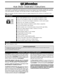
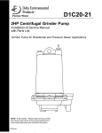
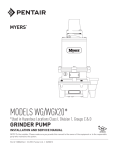
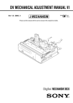
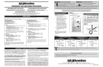
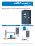
D1P20-21 Submersible Semi-Positive Displacement Grinder Pump Pump Installation and Service Manual NOTE! To the installer: Please make sure you provide this manual to the owner of the pumping equipment or to the responsible party who maintains the system. 23833A593 1 GENERAL INFORMATION Thank you for purchasing your Delta Environmental pump. To help ensure years of trouble-free operation, please read the following manual carefully. Warning: Risk of Electrical Shock — This pump has not been investigated for use in swimming pool areas. Before Operation: Read the following instructions carefully. Reasonable care and safe methods should be practiced. Check local codes and requirements before installation. Warning: Risk of Electrical Shock — This pump is supplied with a grounding conductor and grounding-type attachment plug. To reduce risk of electrical shock, be certain that it is connected only to a properly grounded, grounding-type receptacle. Attention: This manual contains important information for the safe use of this product. Read this manual completely before using this product and refer to it often for continued safe product use. DO NOT THROW AWAY OR LOSE THIS MANUAL. Keep it in a safe place so that you may refer to it often. 1. Connect only to a properly grounded, groundingtype receptacle or control panel. 2. Septic tank to be vented in accordance with local plumbing codes. 3. Do not smoke or use sparkable electrical devices or flame in a septic (gaseous) or possible septic sump. Unpacking Pump: Remove pump from carton. When unpacking unit, check for concealed damage. Claims for damage must be made at the receiving end through the delivery carrier. Damage cannot be processed from the factory. 4. A septic sump condition may exist and if entry into sump is necessary, then (1) provide proper safety precautions per OSHA requirements and (2) do not enter sump until these precautions are strictly adhered to. WARNING: Before handling these pumps and controls, always disconnect the power first. Do not smoke or use sparkable electrical devices or flames in a septic (gaseous) or possible septic sump. 5. Do not install pump in locations classified as hazardous per N.E.C., ANSI/NFPA 70 - 1999. Failure to heed above cautions could result in injury or death. Always disconnect the pump and controls from its power source before handling or making any adjustments. PUMP CAUTIONS AND WARNINGS 1. CAUTION - To reduce risk of electrical shock, pull plug before servicing this pump. 7. For use with maximum 140°F water. 8. Tank should be vented in accordance with local plumbing codes and should not be installed in locations classified as hazardous, in accordance with the National Electrical Code, ANSI/NFPA 70 1999. 2. WARNING: Risk of electrical shock - This pump has not been investigated for use in swimming pool areas. 3. WARNING - See installation and service manual for proper installation. 9. CAUTION - Risk of electric shock. Do not remove cord and strain relief. Do not connect conduit to pump. 4. WARNING - To reduce risk of electrical shock, pump is provided with grounding wire. Be certain that it is connected to ground. 10. WARNING - Severe injury may result from accidental contact with moving cutters. Keep clothing, hands and feet away from cutters any time power is connected to the pump. 5. WARNING - Hazardous moving parts. To reduce the risk of injury, disconnect power before servicing pump. 11. CAUTION - Never work on pump with power on. Make sure that the ground wire is securely connected and that the unit is properly grounded in accordance with local codes. 6. CAUTION - To reduce the risk of electric shock, DO NOT remove cord or strain relief. DO NOT connect conduit to pump. Electrical installations shall be in accordance with the National Electrical Code and all applicable local codes and ordinances. 2 23833A593 PUMP INSTALLATION Pump Not Operating Or In Storage: Pumps with carbon ceramic seals must have manually rotated (6 revolutions) after setting non-operational for 3 months or longer and prior to electrical start-up. Pump Description: The Delta Environmental pump covered by this instruction manual is a submersible grinder pump. The cutter blades are on the suction side of the semipositive displacement pump impeller and discharge directly into the inlet of the impeller. The integra stainless steel pump motor shaft is sealed by a single mechanical seal. Installing Pump In Sump: Before installing pump in sump, lay it on its side and rotate grinder shaft. Stator boot and rotor may be slightly stuck due to factory test water so it must be broken loose by rotating shaft with a screwdriver at grinder end. The common shaft should turn with a slight resistance. Slight lubrication by means of a small amount of lubricating oil down the cavity inlet of the stator boot and rotating shaft to pre-lube stator boot and rotor before start is recommended. Do not connect the power until after this test. Clean all trash and sticks from sump and connect pump to piping. A check valve must be installed on each pump. Two ball bearings are used to handle the loads in this design. The upper bearing takes radial loads, while the larger lower bearing handles both thrust and radial loads. Both bearings are permanently lubricated by the dielectric oil in the motor housing. The motor is fixed within the motor housing and is completely submerged in the dielectric oil for maximum heat transfer. The motor housing and seal chamber are completely sealed with “O” rings located at mating part faces. The power cord entry system is designed to give reliable sealing. Location: If pump is installed in an existing basin or concrete sump, the piping can either be connected permanently or rails and brackets can be furnished for mounting to walls of basin. In either case, be sure that the Delta Environmental non-clog check valve is used and that the pump is submerged in a vertical position. The complete factory built packaged system is recommended for the most satisfactory installation and generally for the lowest cost where expensive installation labor is involved. The first seal is made by compression of a rubber gasket by the cord grip, thereby expanding to fill the cord entry of the motor housing. The cord grip forms a second seal around the molded cord end and provides strain relief. Application: This pump is designed for either residential or industrial sewage discharge applications with a pH ranging from 5 to 9, specific gravities from 0.9 to 1.1, viscosities ranging from 28 to 35 S.S.U. and temperatures up to 140°F. Making Electrical Connections: All electrical wiring must be in accordance with local code, and only qualified electricians should make the installation. Complete wiring diagrams are included for use in making the installation. All wires should be checked for shorts to ground with an ohmmeter or megger after the connections are made. This is important, as one grounded wire can cause considerable trouble. Receiving Pump: Inspect pump on arrival for possible concealed damage in shipping. Any damage should be reported immediately to delivering carrier. Claims for damage must originate at the receiving end. Claims for shipping damage can not be processed at the factory. Codes: All local wiring codes must be observed. Consult the local inspector before installation to avoid costly delays that can occur due to rejection after job is finished. PUMP OPERATIONS Starting the Pump: WARNING: Severe injury may result from accidental contact with moving cutter. Keep clothing, hands and feet away from cutter any time power is connected to the pump. 4. Turn pump on. If pump runs and sump liquid does not pump down, stop pump and close discharge gate valve. Then lift pump until sealing flange is open to vent off trapped air. Lower pump, open discharge valve, and start the pump again. To start the pump, perform the following steps in order: 1. Grinder pump is single phase; no rotation check is necessary. CAUTION: Semi-positive displacement pump is designed to operate at minimum 5 GPM capacity. Running pump at shut-off condition or with gate valve closed can result in damage to the pumping stator boot and rotor. 2. Run water into sump until motor is covered. 3. Open gate valve in discharge line. 23833A593 3 5. Level control should be set so that pump turns off when level is about 2 inches above inlet of pump suction and turns on when level is about 2 inches above motor. 7. Check resistance of windings. (See Chart). If not within guidelines, return pump to an authorized service or repair center. As the motors are oil filled, no lubrication or other maintenance is required. 6. If problems occur, check power source. Make sure a separate supply line is available. Verify voltage supply. PUMP MAINTENANCE 4. If necessary to replace stator boot (21), remove screws (9) and retainer ring (8) from volute (1). Stator boot (21) can now be lifted out from the volute recess. To replace pump rotor (22), use a suitable size center punch and remove lower roll pin (6) from common shaft. Pump rotor (22) can now slide off common shaft. CAUTION: Never work on pump with power on. Make sure that the ground wire is securely connected and that the unit is properly grounded in accordance with local codes. CAUTION: Severe injury may result from accidental contact with moving cutter. Keep clothing, hands and feet away from cutter any time power is connected to the pump. 5. Clean all parts thoroughly before proceeding with reassembly. Slide new rotor (22) on common shaft and carefully replace lower roll pin (6). Place stator boot (21) back in volute recess, replace retainer ring (8) and tighten screws (9). Place volute (1) carefully back over rotor (22) and reattach to seal/ bearing housing (2) with socket head screws (12). Replacing Cutter Parts: If necessary to replace grinder parts because of wear or to inspect for clogging: 1. Close gate valve at pump discharge. 6. Replace radial cutter (3) on common shaft. Lightly tap radial cutter (3) clockwise to ensure full engagement onto common shaft. 2. Turn off circuit breaker. CAUTION: Never work on pump with power on. Be sure ground wire from pump is connected to a good ground such as a water pipe. 7. Replace stationary cutter assembly (4) and screw down with screws (5). Carefully rotate shaft by using screwdriver in slot on shaft, to ensure free rotation of pump. 3. Remove pump from sump. 4. Unscrew screws (5) and remove stationary cutter ring assembly (4). Radial cutter (3) can be screwed off the common shaft by lightly tapping cutter and unscrewing counterclockwise while holding end of common shaft with a screwdriver in slot at cutter end of shaft. 8. Plug pump into power source and operate for a few seconds only (refer to caution note below) to ensure parts are not rubbing under electrical operation. 9. Replace stationary cutter assembly (4), and screw down with screws (5). 5. Radial cutter (3) and stationary cutter (4) can now be inspected for wear and replaced if necessary. 10. Plug pump into power and operate for a few seconds only to ensure parts are not rubbing. Stator Boot and Rotor Inspection and/or Replacement: If necessary to inspect or replace the stator boot and rotor, the following procedure should be followed. CAUTION: Do not run dry, otherwise damage to stator boot can occur. Replacing Seal: 1. Drain the oil from the pump by removing the fill plug (10) located on the side of the motor housing (18). 1. Unscrew socket head screws (12) and remove volute case (1). NOTE: Turning common shaft clockwise while removing volute case can ease removal. 2. Radial cutter (3) and stationary cutter (4) can be inspected for wear and replaced if necessary. 2. Remove the volute and cutters per the instructions listed under “Stator Boot and Rotor Inspection and/ or Replacement” and “Replacing Cutter Parts” sections of this manual. 3. Stator boot and rotor are now exposed to check for any obstructions in or wear of stator boot. 3. Remove the pump rotor per instructions listed under “Replacing Grinder Parts” section in this manual. 4 23833A593 4. Remove the seal (17) rotating elements by sliding the spring bellows off the common shaft, then using two screwdrivers, slide the carbon seal assembly off by prying on the retaining ring. NOTE: It is normal to observe some air bubbles in the seal area initially as the seal seats. If bubbles do not stop within a few seconds, the seal is either not properly installed or is damaged. 5. Using a screwdriver, break the old stationary portion of the seal (17) to allow for removal. 9. Reassemble the pump rotor, cutter and volute as outlined in the “Replacing Cutter Parts” section of this manual. 6. Take the stationary portion of the new seal (17), and lube the rubber material with good quality dielectric oil. Press the stationary portion of the new seal into the seal/bearing housing (2). 10. Refill motor housing with a good quality dielectric oil. Fill the motor housing so that the tops of the motor windings have been covered, but leave an air gap to allow for expansion of the oil. CAUTION: Do not reuse old seal parts. Replace all parts with new. Mixing old and new parts could cause immediate seal failure NOTE: When applying power, be sure the pump is restrained from turning by holding the pump at the motor housing, or by clamping it in a holding fixture. 7. Using a good quality dielectric oil, lube the rubber material on the carbon seal assembly (17) and press it on the common shaft. WARNING: Severe injury may result from accidental contact with moving cutter. Keep clothing, hands and feet away from cutter any time power is connected to the pump. 8. Using a pressure gauge with a fill stem, pressurize the motor housing no more than 7 psig with dried air and check for leaks. If after several minutes the gauge reads the same, the seal is good and you can continue with assembly. TROUBLESHOOTING Pump overloads motor 1. Specific gravity or viscosity of liquid too high 2. Speed too high 4. Pump clogged 5. Defective bearings No liquid delivered 1. Pump air bound 2. Discharge head too high 3. Pump or piping plugged Insufficient liquid delivered 1. Discharge head too high 2. Cutter partially plugged or damaged 3. Stator boot or rotor damaged or worn Pump is noisy 1. Defective bearings 2. No diametral clearance between radial cutter and cutter ring Insufficient discharge pressure 1. Air or gases in liquid 2. Stator boot or rotor damaged or worn 23833A593 If the cause of the trouble cannot be determined and corrected as outlined above, contact your nearest factory representative. 5 D1P20-21 PERFORMANCE CURVE Total Head in Feet Consult Delta Environmental Products sales representative for intermittent use. 6 23833A593 REPLACEMENT PARTS Product improvements are made from time to time. The latest part design will be furnished as long as it is interchangeable with the old part. When ordering replacement parts, always furnish the following information: (1) pump serial number, (2) pump model and size, (3) part description, (4) part number, (5) impeller diameter (if ordering impeller), (6) quantity required, and (7) shipping instractions. Ref. No. 1 2 3 4 5 6 7 8 9 10 11 12 13 14 15 16 17 18 19 20 21 22 23 24 25 26 27 Part No. 14624-000-2 14569-001-2 21582B000 21584B000 00176-006-1 00180-002-1 00834-023-1 14627-000-1 00892-007-1 14981-001-1 00101-008-1 00178-006-1 00077-011-1 04580-001-1 14573-000-1 27429A001 25327D000 14885-000-1 05570-005-1 05030A234 05014A193 05030A235 14587-000-1 14761-000-1 14762-101-1 14885-020-3 14570-100-1 11009A003K Part Description Case - Volute Housing - Seal/Bearing Cutter - Radial Cutter - Stationary Screw - Cap Pin - Roll, Lower O-Ring Ring - Retainer Screw - Ring Retainer Pipe Plug Screw - Cap Screw - Socket O-Ring Screw - Drive Seal - Shaft Nameplate, 230V Housing - Motor Screw - Shaft, Motor Washer - Shaft Impeller Washer - SST 1/32 Thick Gasket - Rubber Washer - SST 3/32 Thick Nut - Cord Stator - Pump Rotor - Helix Cord - Power Motor Oil, transformer Qty 1 1 1 1 3 1 1 1 3 1 4 4 1 2 2 1 1 1 1 1 1 1 1 1 1 1 1 1 Use the Delta Environmental standard wastewater warranty for 2 HP grinders. WINDING RESISTANCE CHART 23833A593 7 Model Volts Phase Start Winding Run Winding D1P20-21 230 1 3.15 3.05 LIMITED WARRANTY Delta Environmental Products warrants to the original purchaser of each Delta Environmental Product grinder pump system(s) that any part thereof which proves to be defective in material or workmanship within two year from date of installation or 27 months from manufacture date, (extended warranty available) whichever comes first, will be replaced at no charge with a new or remanufactured part, F.O.B. factory. Purchaser shall assume all responsibility and expense from removal, reinstallation, and freight. Any item(s) designated as manufactured by others shall be covered only by the express warranty of the manufacturer thereof. This warranty does not apply to damage resulting from accident, alteration, design, misuse or abuse. The pump must be installed, operated, and maintained in accordance with the published instructions of the appropriate Installation & Service Manual. All dual seal grinders must have seal failure and heat sensors attached and functional for Warranty to be in effect. If a seal failure should occur, Delta Environmental Products will cover only the lower seal and labor thereof. Labor based on Authorized Service Center contract allowance. If the heat sensor is not attached and functional, Warranty is void. If the seal failure sensor is not attached and functional, Warranty is void. If the material furnished to the Buyer shall fail to conform to this contract or to any of the terms of this written warranty, Delta Environmental Products shall replace such nonconforming material at the original point of delivery and shall furnish instruction for its disposition. Any transportation charges involved in such disposition shall be for the Buyer’s account. The Buyer’s exclusive and sole remedy on account or in respect of the furnishing of material that does not conform to this contract or to this written warranty, shall be to secure replacement thereof as aforesaid. Delta Environmental Products shall not in any event be liable for the cost of any labor expended on any such material or for any incidental or consequential damages to anyone by reason of the fact that such material does not conform to this contract or to this written warranty. ALL IMPLIED WARRANTIES, INCLUDING THE IMPLIED WARRANTY OF MERCHANTABILITY AND THE IMPLIED WARRANTY OF FITNESS FOR A PARTICULAR PURPOSE, ARE DISCLAIMED TO THE SAME EXTENT AS THE EXPRESS WARRANTY CONTAINED HEREIN. Some states do not allow limitations on how long an implied warranty lasts, so the above limitation may not apply to you. MANUFACTURER EXPRESSLY DISCLAIMS AND EXCLUDES ANY LIABILITY FOR CONSEQUENTIAL OR INCIDENTAL DAMAGES FOR BREACH OF ANY EXPRESS OR IMPLIED WARRANTY ARISING IN CONNECTION WITH THIS PRODUCT, INCLUDING WITHOUT LIMITATION, WHETHER IN TORT, NEGLIGENCE, STRICT LIABILITY CONTRACT OR OTHERWISE. Some States do not allow the exclusion or limitation of incidental or consequential damages, so the above limitation or exclusion may not apply to you. This warranty gives you specific legal rights, and you may also have other rights which vary from State to State. 8 23833A593 7/05 Single Phase Simplex SJE-Rhombus® Type 112 Installation Instructions and Operation/Troubleshooting Manual This control panel must be installed and serviced by a licensed electrician in accordance with the National Electric Code NFPA-70, state and local electrical codes. All conduit running from the sump or tank to the control panel must be sealed with conduit sealant to prevent moisture or gases from entering the panel. NEMA 1 enclosures are for indoor use only, primarily to provide a degree of protection against contact with enclosed equipment. Cable connectors are not required to be liquid-tight in NEMA 1 enclosures. Do not use NEMA 1 enclosures if subjected to rain, splashing water or hose-directed water. NEMA 4X enclosures are for indoor or outdoor use, primarily to provide a degree of protection against corrosion, windblown dust and rain, splashing water and hose-directed water. Cable connectors must be liquid-tight in NEMA 4X enclosures. Installation A standard Type 112 panel is designed to operate with three floats. These floats operate pump stop, pump start, and high level alarm functions. Warranty void if panel is modified. Call factory with servicing questions: 1-800-RHOMBUS (1-800-746-6287) NOTE: Options ordered may affect the number of floats and their functions. Please reference the schematic provided with the control panel for proper installation. Installation of Floats CAUTION: If control switch cables are not wired and mounted in the correct order, the pump system will not function properly. WARNING: Turn off all power before installing floats in pump chamber. Failure to do so could result in serious or fatal electrical shock. 1. Use float label kit to label floats for specific operation (stop, start, alarm, etc.). See schematic for float options. Manufactured by: 2. Determine your normal operating level, as illustrated in Figure 1. 3. Mount float switches at appropriate levels as illustrated in Figures 24. Be sure that floats have free range of motion without touching each other or other equipment in the basin. If using the mounting clamp; follow steps 4-6. 22650 County Highway 6 P.O. Box 1708 Detroit Lakes, Minnesota 56502 USA 1-888-DIAL-SJE (1-888-342-5753) Phone: 218-847-1317 Fax: 218-847-4617 E--mail: [email protected] Website: www.sjerhombus.com 4. Place the cord into the clamp as shown in Figure 2. 5. Locate the clamp at the desired activation level and secure the clamp to the discharge pipe as shown in Figure 2. NOTE: Do not install cord under hose clamp. 6. Tighten the hose clamp using a screwdriver. Over tightening may result in damage to the plastic clamp. Make sure the float cable is not allowed to touch the excess hose clamp band during operation. ©SJE-Rhombus PN1008704D • Rev 10/09 NOTE: All hose clamp components are made of 18-8 stainless steel material. See your SJE-Rhombus® supplier for replacements. Installation Instructions Mounting the Control Panel 1. Determine mounting location for panel. If distance exceeds the length of either the float switch cables or the pump power cables, splicing will be required. For outdoor or wet installation, we recommend the use of an SJE-Rhombus® liquid-tight junction box with liquid-tight connectors to make required connections. You must use conduit sealant to prevent moisture or gases from entering the panel. 2. Mount control panel (mounting flanges are furnished with control panel). 3. Determine conduit entrance locations on control panel. Check local codes and schematic for the number of power circuits required. NOTE: Be sure the proper power supply voltage, and phase are the same as the pump motor being installed. If in doubt, see the pump identification plate for electrical requirements. 4. Drill proper size holes for type of connectors being used. 9. Identify and label each wire before pulling through conduit into control panel and junction box. Pull pump power cables and control switch cables through connectors into junction box. Make wire splice connections at junction box. 10. Firmly tighten all fittings on junction box. Insure all cable connectors are liquid-tight and sealed. 11. If a junction box is not required, identify and label cables on both float and stripped ends. 12. Connect pump and float wires to proper position on terminals. See schematic inside control panel for terminal layouts. 13. Connect control, alarm and pump power conductors to proper position on terminals. See schematic inside control panel for terminal connections. NOTE: It is the recommendation of the factory to use separate pump and control/alarm power sources. VERIFY CORRECT OPERATION OF CONTROL PANEL AFTER INSTALLATION IS COMPLETE. NOTE: If using conduit, be sure that it is of adequate size to pull the pump and switch cables through. You must use conduit sealant to prevent moisture or gases from entering the panel. 5. Attach cable connectors and/or conduit connectors to control panel. FOR INSTALLATION WITHOUT A SPLICE, GO TO STEP 11; FOR INSTALLATION REQUIRING A SPLICE, FOLLOW STEPS 6-10. 6. Determine location for mounting junction box according to local code requirements. Do not mount the junction box inside the sump or basin. 7. Mount junction box to proper support. 8. Run conduit to junction box. Drill proper size holes for the type of conduit used. Attach liquid-tight connectors to junction box. FIGURE 1Three float simplex - pump down installation Installation Instructions FIGURE 2 Mounting clamp detail FIGURE 3 Internally weighted float FIGURE 4 Float with cable weight Operations SJE-Rhombus® Type 112 control panels are designed to operate in a three float system as standard. When all floats are in the open or OFF position, the panel is inactive. As the liquid level changes and closes the stop float, the panel remains inactive until the start float also closes. At this point the pump will start, providing the HOA switch is in the AUTOMATIC mode and the power is ON. The pump will remain ON until both the stop and start floats open (return to the OFF position). If the liquid level travels beyond both the stop and start floats and reaches the alarm float, the alarm will be activated. The alarm horn can be silenced by moving the test/normal/silence switch to the silence position. Alarm System (Horn and Indicator) When an alarm condition occurs, a red light and horn will be activated. If the test/normal/silence switch is moved to the silence position, the horn will be silenced. When the alarm condition is cleared, the alarm system is reset. The alarm system can be tested by moving the test/normal/silence switch to the test position. HOA Switch A hand-off-automatic switch is provided for the pump. In the hand mode, the pump will turn on unless other safety features are employed. In the automatic mode, the pump will turn on from commands by the float switches. Pump Run Light The run light will be ON in either the hand or the automatic mode when the pump is called to run. Circuit Breaker (optional) The pump circuit has a thermal-magnetic circuit breaker which provides pump disconnect and branch circuit protection. Dry Auxiliary Contacts (optional) Normally open - Contacts are open under normal conditions and closed when alarm condition is present. Normally closed - Contacts are closed under normal conditions and open when alarm condition is present. Both types automatically reset once alarm condition is cleared. NOTE: Some options ordered may not be included in this manual. For information regarding the operations of options not listed here or servicing questions, please call a SJE-Rhombus® customer service technician at 1-800-RHOMBUS (1-800-746-6287) Warranty void if panel is modified. Troubleshooting Alarm Horn Moving the test/normal/ silence switch to the test position or activating the alarm float should turn on the alarm horn. If the horn does not sound, replace horn with same type. Checking the float resistance - The float resistance can be measured to determine if the float is operating correctly or is defective. Use the following procedure to measure the float resistance. WARNING: Disconnect incoming power to panel. 1. Isolate the float by disconnecting one or both of the float leads from the float terminals. Alarm Light 2. Moving the test/normal/silence switch to the test position or activating the alarm float should turn on the alarm light. If the light does not activate, replace with same type. Place one ohmmeter lead on one of the float wires, and the other ohmmeter lead on the other float wire. 3. Place the ohmmeter dial to read ohms and place on the R X 1 scale. With the float in the “off” position, the scale should read infinity (high resistance). Replace the float if you do not get this reading. With the float in the ON position, the scale should read nearly zero (very low resistance). Replace the float if you do not get this reading. Circuit Breaker (optional) Check each pole of the circuit breaker for proper resistance reading using the following procedure. WARNING: Disconnect incoming power to panel. 1. Isolate the circuit breaker by disconnecting either line side or load side wires. 2. Place the ohmmeter leads across the corresponding line and load terminals of each pole. 3. With the ohmmeter on the R X 1 scale and the breaker in the OFF position, the reading should be infinity (very high resistance). With the breaker in the ON position, the reading should be nearly zero ohms (very low resistance). If the readings are not as stated, replace the circuit breaker with one of the same ratings. NOTE: Readings may vary slightly depending on the accuracy of the measuring device. Float Controls Check the floats during their entire range of operation. Clean, adjust, or replace damaged floats. NOTE: Readings may vary depending on the length of wire and accuracy of the measuring device. Fuses Check the continuity of the fuse. With power OFF, pull the fuse out of the fuse block. With the ohmmeter on the R X 1 scale, measure resistance. A reading of infinity indicates a blown fuse and must be replaced. Replace fuse with same type, voltage and amp rating. Magnetic Contactor Coil WARNING: Disconnect incoming power to panel. Check the coil by disconnecting one of the coil leads. Measure the coil resistance by setting the ohmmeter on the R X 1 scale. A defective coil will read zero or infinity, indicating a short or opened coil respectively. Replace defective contactor with same type. NOTE: Readings may vary depending on the accuracy of the measuring device. SJE-Rhombus® Three-Year Limited Warranty SJE-RHOMBUS® warrants to the original consumer that this product shall be free of manufacturing defects for three years after the date of consumer purchase. During that time period and subject to the conditions set forth below, SJE-RHOMBUS® will repair or replace, for the original consumer, any component which proves to be defective due to defective materials or workmanship of SJE-RHOMBUS®. ELECTRICAL WIRING AND SERVICING OF THIS PRODUCT MUST BE PERFORMED BY A LICENSED ELECTRICIAN. THIS WARRANTY DOES NOT APPLY: (A) to damage due to lightning or conditions beyond the control of SJE-RHOMBUS®; (B) to defects or malfunctions resulting from failure to properly install, operate or maintain the unit in accordance with printed instructions provided; (C) to failures resulting from abuse, misuse, accident, or negligence; (D) to units which are not installed in accordance with applicable local codes, ordinances, or accepted trade practices, and (E) to units repaired and/or modified without prior authorization from SJE-RHOMBUS®. Some states do not allow limitations on how long an implied warranty lasts, so the above limitation may not apply to you. Some states do not allow the exclusion or limitation of incidental or consequential damages, so the above limitation or exclusion may not apply to you. This warranty gives you specific legal rights, and you may also have other rights which vary from state to state. TO OBTAIN WARRANTY SERVICE: The consumer shall assume all responsibility and expense for removal, reinstallation, and freight. Any item to be repaired or replaced under this warranty must be returned to SJE-RHOMBUS®, or such place as designated by SJE-RHOMBUS®. ANY IMPLIED WARRANTIES OF MERCHANTABILITY OR FITNESS ARE LIMITED TO THE DURATION OF THIS WRITTEN WARRANTY. SJE-RHOMBUS® SHALL NOT, IN ANY MANNER, BE LIABLE FOR ANY INCIDENTAL OR CONSEQUENTIAL DAMAGES AS A RESULT OF A BREACH OF THIS WRITTEN WARRANTY OR ANY IMPLIED WARRANTY.