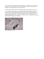
1
Headset construction for mic and PTT.
My application for the headset is “motorcycle safety marshal” for charity events. This interface
provides a PTT jack and a headset condenser microphone jack using commonly available parts.
The FT-8800r remote kit already includes audio output via a monaural cable with 1/8” phone
plug at the radio end and monaural 1/8” phone jack for the external speaker. I haven’t looked
too closely at this cable, but I do know that if it wasn’t part of the “kit” I would have made my
own from audio grade coax. A typical “computer” headset with stereo speakers and a condenser
microphone will need this interface plus a 1/8” stereo to mono adapter plug (for the external
speaker jack) to provide in and out audio.
The PTT, a simple momentary SPST switch, can be sized and mounted as you desire. A WWW
search for “PTT” will find pages of sites that have PTT switches for aircraft, off road vehicle,
hang glider, and other mobile applications. They vary in size and intended application but most
share one thing in common, a hook-and-loop strap for mounting. Some sites advertise these for
“finger” or “thumb” use - you wrap it around a digit and press with another. Different strokes
for different folks I guess. I mention the finger application because those sites tend to have the
lowest prices. Don’t forget eBay. That is where I got mine, which came with a 3/32” mono
plug. On motorcycles, snowmobiles and quadrunners the strap loops around the left handlebar
grip. On aircraft, dune buggies and go-karts it loops around the yoke or steering wheel. If I am
inclined to bring the radio inside this winter the PTT strap will wrap around the pill bottle
containing the interface. – I might make another interface from a larger bottle and mount a SPST
momentary switch through the snap-on lid.
Parts List:
1 – 6P6C modular plug (RJ-22, -25). Radio Shack sells them in pack of six, PN 279-421
6” – RJ-14 or RJ-25 telephone cable. You only need four conductors, so RJ-14 will work.
2 – 1/8” or 3/32” phone jacks, whichever fit the microphone and PTT you decide to use.
1 – small piece of perf board, cardboard, credit card, or whatever, to hold the components. All
the wiring is point to point so if the material can handle putting holes through it to pass the
capacitor and resistors leads through then it is suitable. I used perf board because I wanted to be
able to wrap the RJ-14 cable with thread as strain relief.
R1 – 27K ohm ½ watt carbon resistor
R2 – ~ 2K ohm ½ watt carbon resistor
C1 – a 10 microfarad, 25 volt electrolytic capacitor, it works better if polarized properly, but
worked on the breadboard reversed until I caught the error.
1- Pill bottle of your choice; but don’t choose those brown prescription bottles from the
pharmacy, they are too brittle. My pill bottle has a screw on cap, a snap on cap might have been
a better choice.
1- SPST momentary switch for PTT, you’ll be holding this for the duration of your transmission
- if you are long-winded use one with a low effort to “make” the switch.
1- condenser headset microphone. Seems like there is always a sale on the Labtec LVA-73xx
headsets. I found a local computer store selling them for $5 each in the box. I bought more than
one. Computer gamers have given high marks to the Radio Shack PN 33-1187, which is a
combination of stereo speakers and a condenser microphone ending in two 1/8” stereo plugs. If
your application is in the shack, this might be a good choice. RS had them for a few bucks off
the regular price when I started this project so I bought one to try. It really is good quality for the
price, under $20. It has very comfortable speaker earpads and a flip-up mic boom with enough
movement damping to stay where you put it. I hooked the mic to the breadboard version and it
sounded good – most condenser mics do sound good though. I’m using one of the Labtec mics
in my helmet because boom mount is flatter (but not as well damped). [For those who have to
know, I’m using a helmet that already had J&M speakers installed, but wired to a 1/8” stereo
plug because I can use the helmet as speakers for MP3 players or my GPS (or now my FT-8800r)
when I’m traveling on the motorcycle. The wiring diagram to adapt from 1/8” to the 5 pin
“MIDI” connectors on the Goldwing is available on many Goldwing websites.]
The modular microphones for the FT-8800r, 7800r, 8900r, and 1802m use a 6P6C modular
connector. The following information is from the Heil Sound website’s Yaesu tips. (BTW
another excellent source for microphone pin out data is G4WPW’s website.) These are the four
conductors used in this interface.
6-pin Modular (FM Mobiles: FT-1500/1802/2800/7800/8800/8900)
Pin 3: +8V
Pin 4: Ground
Pin 5: Microphone In
Pin 6: PTT
[The spec I found for pin 3 of the FT-8800r is +9V rather than +8V, but the rest is the same]
Internally, the MH48A6 and MH42B6 microphones of have various implementations of resistor
networks (I’ve heard it described as a cascade) to provide voltage references to the radio. Most
of those voltage modifiers are related to what is termed S1 and S2, but the PTT is also part of the
“cascade.” It is such a small part of the voltage matrix that you can ignore the cascade and wire
a resistor (R1, 27K) in series with the PTT switch and the radio will be happy to transmit for as
long as you hold (make) the switch. Regrettably Yaesu did not think the FT-8800r user manual
should show the pin numbering for the microphone jack. The writers of the FT-1802m manual
did not make that omission. Rather than paste the diagram from the FT-1802m manual into this
document (and violate a copyright) the numbering works this way. Hold the 6P6C plug with the
contacts toward the radio and the locking tab at the bottom and count from right to left 1-2-3-45-6 with “pins” 3 through 6 being the leftmost – closest to the front of the radio when plugged in.
For those who like pictures – sorry, I can’t produce a good one. I can make an ugly drawing or
two!
[x]
| | | | | | where the [x] is the locking tab
Facing the contact side the pins are 6 5 4 3 2 1
[x]
| | | | | | where the [x] is the locking tab
Facing the cord side the pins are 1 2 3 4 5 6
These are both PLUG drawings. Please don’t get this wrong. I have been told bad things can
happen inside the radio. If in doubt, the FT-1802m manual is available on the Yaesu Vertex
website – look on page 10.
The rest of the parts power the condenser mic element and block the DC from getting to pin 5. A
condenser microphone has a lot of good qualities and one bad one. It is small, cheap to
manufacture, has good frequency response, has good output signals, but, it needs to be biased by
a DC voltage. This has to do with internal components of the mic element that don’t need to be
discussed here – just accept that the condenser mic element needs to have a small DC current to
work. The voltage is available at the microphone jack at pin 3. R2 provides load and voltage
drop to ensure that the mic doesn’t see the full voltage. The recommended resistance I found for
9V is around 2K ohm. – if you start with a condenser mic element, be aware that it is polarized.
If it doesn’t work one way connect it the other. It usually takes more than 15v to fry one from
reversed voltage so it should survive this mistake at 9V.
The circuit looks like this, well not really; but this is the ugly drawing version
Pin 3 o------/\/\ R2 /\/\/\-----|
________|
|
Pin 5 o---|C1|----|----------------- [mic]<
|
|
Pin 4 o--------GND-----------|--|
|
Pin 6 o-----/\/\/\ R1 /\/\/\/---- |
The PTT jack wires across from Pin 6 to Pin 4 so that the switch will short from pin 6 to ground
through the 27K ohm resistor.
The mic jack wires in where the [mic]< symbol is (from Pin 4 to Pin 5 with C1 between the
output and Pin 5; and Pin 3 connects to the microphone through R2 between C1 and the
microphone output. If your microphone already has a phone plug, the + output of the mic is on
the tip connector. For some reason, most lightweight, computer style, headset mics have stereo
plugs. There is only one wire pair to the mic element – from tip to shank; but most plugs have
the tip electrically tied to the ring also. Check yours with a VOM. If you find the tip and ring
connected you can do as you like with the ring connector on the jack – tie it to the tip or leave it
open, it shouldn’t matter. It does matter if you get confused and tie the ring to the shank – you
will have shorted out the mic element, no damage will result (ask how I know) but no sound will
result from your radio transmission either.
Obviously, this interface does nothing more than provide PTT and adapt a commercially
available small condenser microphone to the radio. It does it in a way that I can take off my
helmet after I dismount the motorcycle without putting stress on the radio’s microphone jack or
using it to disconnect from the radio. All of the switching, direct frequency entry, etc. that are
available on the MH48 are not available here. I don’t need them for my motorcycle purpose. If I
did need them I would consider buying and modifying the Yaesu MEK-2 microphone interface
(disconnect pin 5 from the MH48 jack and add this interface to the MEK-2 box) so that the
MH48A6 can be plugged in at the same time as a headset.
I couldn’t find my RJ-25 crimper when I finished this project (it turned up in my RJ-45/Cat 5
box) so I can attest to the fact that you can properly crimp an RJ-25 using pliers or an RJ-14
crimper and pliers. Radio Shack (I’m starting to feel like I’m doing an unpaid endorsement)
sells a 25 foot RJ-25 phone extension cable for $10 which buys you two factory crimped ends
and plenty of 6 conductor cable. I used RJ-14 cable because I had it on hand when I first
breadboarded the interface. If you go this way, the RJ-14 wires are well supported, even though
offset in the RJ-25 plug, after it is crimped.
Mic/PTT interface, AE5CR