1
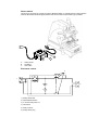
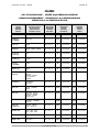
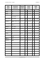
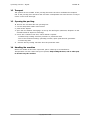
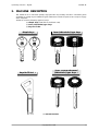
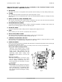
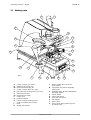
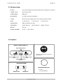
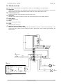
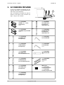
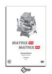
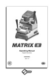
Operating manual
D411774XA
vers. 1.1
®
Operating manual - English
(c)
MATRIX SX
1994 SILCA S.p.A. - Vittorio Veneto
This manual has been drawn up by SILCA S.p.A.
All rights reserved. No part of this publication may be reproduced or used in any form or by any means
(photocopying, microfilm or other) without the permission of SILCA S.p.A.
First published in July 1994
Printed in Vittorio Veneto
by SILCA S.p.A.
via Podgora, 20 (Z.I.)
31029 VITTORIO VENETO (TV) - Italy
-4
Copyright Silca 1994
Operating manual - English
MATRIX SX
CONTENTS
Page
Chapter 1.
1.1
1.2
1.3
1.4
TRANSPORT ........................................................................................................ 3
Packing ............................................................................................................ 3
Transport .......................................................................................................... 4
Opening the packing ..................................................................................... 4
Handling the machine.................................................................................... 4
Chapter 2.
2.1
2.2
2.3
2.4
MACHINE DESCRIPTION ................................................................................ 5-6
Working parts ................................................................................................... 7
Technical data................................................................................................. 8
Graphics............................................................................................................ 8
Electrical circuit................................................................................................ 9
Chapter 3.
ACCESSORIES PROVIDED ............................................................................... 10
Chapter 4.
4.1
4.2
4.3
4.4
MACHINE INSTALLATION and PREPARATION............................................... 11
Checking for damage.................................................................................. 11
Atmospheric conditions ................................................................................ 11
Positioning ....................................................................................................... 11
Description of work station .......................................................................... 11
Chapter 5.
5.1
5.2
5.3
5.4
5.5
5.6
5.7
MACHINE REGULATION and REGISTRATION................................................ 12
Clamps ............................................................................................................ 12
Spring system for LASER (sidewinder) type keys ................................ 13-14
Hand rest......................................................................................................... 15
Tracer point vertical spring system ............................................................. 15
Fitting and regulating the tools................................................................... 16
Setting.............................................................................................................. 17
Micrometric ring nut...................................................................................... 18
Chapter 6.
6.1
6.2
6.3
6.3.1
6.3.2
6.4
6.5
6.6
CUTTING OPERATIONS.................................................................................... 19
Fitting the keys ............................................................................................... 19
Key stop .......................................................................................................... 19
CUTTING DIMPLE KEYS ....................................................................................... 20
Cutting the back ....................................................................................... 20
Inclined cuts ............................................................................................... 20
CUTTING LASER (SIDEWINDER) TYPE KEYS .......................................................... 21
CUTTING NARROW-STEMMED LASER (SIDEWINDER) TYPE KEYS .......................... 22
CUTTING KEYS for FICHET ................................................................................... 23
Chapter 7.
7.1
7.2
7.3
7.4
7.5
MAINTENANCE ................................................................................................ 24
Replacing the belt and adjusting tension ................................................ 24
Replacing the light bulb .............................................................................. 25
Registration/replacement of the vertical carriage tension spring........ 25
Checking and replacing the fuses............................................................. 26
Replacing the electronic board for the keypad ..................................... 26
Chapter 8.
WASTE DISPOSAL............................................................................................. 27
Chapter 9.
9.1
ASSISTANCE ..................................................................................................... 27
How to request service ................................................................................ 27
Copyright Silca 1994
-3
SAFETY DEVICE
The device is connected to a power plug with a differential switch. It activates the key-cutting machine
when the illuminated ON button (B) is pressed and cuts out when the OFF button (C) is pressed.
B
A
A
B
C
C
Safety device
ON button
OFF button
ELECTRICAL CIRCUIT
5
2
1
3
4
1) Safety device inlet
2) Illuminated ON button
3) 3 contacts relay, 220V a.c.
4) OFF button
5) Relay contacts
6) Safety device plug
6
Operating manual - English
MATRIX SX
MATRIX
USE of TOOLS PROVIDED - UTILIZZO degli UTENSILI IN DOTAZIONE
GEBRAUCH DER WERKZEUGE - UTILISATION de les OUTILS EN DOTATION
UTILIZACIÓN de los ÚTILES EN DOTACIÓN
MAIN BRAND
MARCA
MARKE
MARQUE
MARCA
SILCA KEYBLANK
ARTICOLO SILCA
SILCA-ARTIKEL
ARTICLE SILCA
ARTÍCULO SILCA
MACHINE
MACCHINA
MASCHINE
MACHINE
MÁQUINA
TRACER POINT
TASTATORE
TASTER
PALPEUR
PALPADOR
CUTTING TOOL
FRESINO
FRÄSER
FRAISE
FRESA
ABUS (D)
AB40
SLX - SX - S
T1
D401070RA
F1
D701071ZB
AZBE (E)
(CAVERS)
AZ6-AZ7
SLX - SX - S
T42
D408799RA
F42
D708800ZB
CISA (I)
CS48
SLX - SX - S
T1
D401070RA
F1
D701071ZB
DOM (D)
DM21 - DM55 - DM58
SLX - SX - S
T1
D401070RA
F1
D701071ZB
ELCA (D)
TESA (E)
EC5
SLX - SX - S
T1
D401070RA
F1
D701071ZB
FICHET (F)
FT500
SLX - SX - S
T22
D405487RA
F22
D705488ZB
FTH (F)
(YALTRES)
FH12
SLX - SX - S
T5
D401078RA
F5
D701079ZB
GE-GE (A)
GE57
SLX - SX - S
T1
D401070RA
F1
D701071ZB
GIOBERT (I)
SAFE (I)
GT2P - GT2 - GT2BP
SLX - SX - S
T1
D401070RA
F1
D701071ZB
SLX - SX - S
T44
D409147RA
F44
D709148ZB
SLX - SX - S
T22
D405487RA
F22
D705488ZB
SLX - SX - S
T22
D405487RA
F22
D705488ZB
SLX - SX - S
T22
D405487RA
F22
D705488ZB
SLX - SX - S
T22
D405487RA
F22
D705488ZB
T1
D401070RA
F1
D701071ZB
(LANCIA)
GT9AP - GT2AP
(ALFA ROMEO)
GT2CP
HONDA (J)
HON60AP
(LEGEND)
HUF (D)
HU59 - HU58AP
(BMW)
HUF (D)
HU44AP - HU41P
HU61AP - HU55P
HU40P - HU39P
(MERCEDES)
HUF (D)
HU57RP - HU56RP
(VOLVO)
HUF (D)
YMOS (D)
HU43P - YM27P
KABA (CH)
KA1 - KA2 - KA3
KA4 - KA5 - KA6
SLX - SX - S
KABA (CH)
KA2 - KA9
SLX - SX
T43
D408987RA
F43
D708988ZB
KESO (CH)
KE3 (82˚)
SLX - SX - S
T26
D405654RA
F26
D705655ZB
(OPEL-VAUXHALL)
Copyright Silca 1994
-1
Operating manual - English
MAIN BRAND
MARCA
MARKE
MARQUE
MARCA
MATRIX SX
SILCA KEYBLANK
ARTICOLO SILCA
SILCA-ARTIKEL
ARTICLE SILCA
ARTÍCULO SILCA
MACHINE
MACCHINA
MASCHINE
MACHINE
MÁQUINA
TRACER POINT
TASTATORE
TASTER
PALPEUR
PALPADOR
CUTTING TOOL
FRESINO
FRÄSER
FRAISE
FRESA
MCM (E)
MC9
SLX - SX - S
T37
D406653RA
F37
D706654ZB
MCM (E)
MC9
SLX - SX - S
T38
D406656RA
F38
D706657ZB
MCM (E)
MC9
SLX - SX - S
T39
D406658RA
F39
D706659ZB
MCM (E)
MC10R
+ COPPIA ADATTATORI
D711137ZB
SLX - SX - S
T50
D411145RA
F50
D711144ZB
MUL-T-LOCK (IL)
MTK1-MTK2P
SLX - SX - S
SLX - SX - S
T12A
T12B
D501090ZM
D401092RA
F12A
F12B
D701091ZB
D701093ZB
NEIMAN (D)
NE67AP - NE66P - NE66
SLX - SX - S
T22
D405487RA
F22
D705488ZB
SLX - SX - S
T22
D405487RA
F22
D705488ZB
(VOLVO)
NISSAN (J)
NSN10AP - NSN10 - NSN9P
(INFINITI)
SPIDER (IL)
SPR1 - SPR2
SLX - SX - S
T1
D401070RA
F1
D701071ZB
STS (E)
STS5-STS6
SLX - SX - S
T5
D401078RA
F5
D701079ZB
TESA (E)
TE4R
SLX - SX - S
T1
D401070RA
F1
D701071ZB
TESA (E)
TE7
SLX - SX
T5
D401078RA
F5
D701079ZB
TOYOTA (J)
TOY40 - TOY40AP TOY40P
SLX - SX - S
T22
D405487RA
F22
D705488ZB
(LEXUS)
0
YARD
YARDENI (IL)
YD3R
SLX - SX - S
T1
D401070RA
F1
D701071ZB
YMOS (D)
YM30P
(SAAB)
SLX - SX - S
T22
D405487RA
F22
D705488ZB
ZADI (I)
ZD20
SLX - SX - S
T5
D401078RA
F5
D701079ZB
Copyright Silca 1994
Operating manual - English
MATRIX SX
GUIDE TO THE MANUAL
This manual has been produced to serve as a guide for users of the MATRIX SX key-cutting
machine. Read it carefully; it is essential if you wish to operate your machine safely and
efficently.
Consultation
The contents of the manual are divided into sections relating to:
- Transport and handling ...................................................................... Chapter
1
- Checking the safety of the machine ............................................. Chapter
4
- Proper use of the machine ................................................................ Chapters
5-6
- Maintenance ....................................................................................... Chapter
7
Technical terms
Common technical terms are used in this manual.
Fig.1 shows the names of the different parts of the keys most commonly copied with
the MATRIX SX.
Fig. 1
1)
Head
2)
Rim
3)
Stop
4)
Stem
5)
Tip
6)
Back
7)
Cuts
1
1
2
3
4
3
7
6
7
5
5
DIMPLE KEY
LASER (SIDEWINDER)
TYPE KEY
keys with holes of different
dimensions, depths, positions
and shapes.
LASER is the name given to
the special sidewinder milled
keys.
Copyright Silca 1994
1
Operating manual - English
MATRIX SX
GENERAL INSTRUCTIONS
The MATRIX SX key-cutting machine has been designed according to the specifications of the
Machine Directives. Right from the design stage risks for the operator have been eliminated in
all areas: transport, key-cutting, regulation and maintenance.
Other risks have been eliminated by the use of protective devices for the operator.
The protective devices used are designed not to provoke further risks and, above all, they
cannot be ignored unless deliberately cut out. They do not hinder visibility of the work area.
A special adhesive label is attached to the machine warning the operator to use goggles during
the cutting operations, and this is strongly recommended in this manual.
The material used in the manufacture of this machine and the components employed during
use of the machine are not dangerous and their use complies with standards.
Use
The MATRIX SX must be installed and used in the way laid down by the manufacturer.
If the key-cutting machine is used differently or for purposes different from those described in this
manual, the customer will forego any rights he may have over Silca S.p.A. Furthermore,
unforeseen danger to the operator or any third parties may arise from incorrect use of the
machine.
Negligence in the use of the machine of failure on the part of the operator to observe the
instructions given in this manual are not covered by the guarantee and the manufacturer
declines all responsability in suck cases.
It is therefore indispensable to read the operating manual carefully in order to make the best
use of the MATRIX SX sand benefit from its potential.
Further risks
There are no further risks arising from the use of the MATRIX SX key-cutting machine.
Protection and safety precautions for the operator
The MATRIX SX key-cutting machine is built entirely to standards. The operations for which it has
been designed are easily carried out at no risk to the operator.
The adoption of general safety precautions (wearing protective goggles) and observation of
the instructions provided by the manufacturer in this manual eliminate all human error, unless
deliberate.
The MATRIX SX key-cutting machine is designed with features which make it completely safe in
all its parts.
● Power supply
The machine is supplied with electricity by means of an earthed plug and differential switch.
● Start-up
The machine is started up by means of the master switch on the back.
● Operations
The motor start switch activates the cutting tool.
● Illumination
The work area is illuminated by a lamp which operates when the machine is switched on with
the master switch.
● Maintenance
The operations to regulate, service, repair and clean the machine have been devised in the
simplest possible way. There is no danger of removable parts being replaced wrongly or
unsafely.
● Machine identification
The MATRIX SX key-cutting machine is
®
SILCA SpA - Via Podgora 20 (Z.I.)
31029 VITTORIO VENETO (TV) ITALY
(0438) 9136
Telefax (0438) 913800
Telex 410579 SILCA I
☎
provided with an identification label
which shows the serial number (Fig.2).
CE mark
year of
manufacture
TIPO
TYPE
N˚ MATRICOLA
SERIAL No.
VOLT
Hz.
A.
Fig. 2
2
Copyright Silca 1994
WATT
manufacturer’s
identity
Operating manual - English
MATRIX SX
1. TRANSPORT
The MATRIX SX key-cutting machine is easily transported and is not dangerous to handle.
The packed machine can be carried by one person.
1.1 Packing
The packing used for the MATRIX SX guarantees that the machine will travel safely without
danger of damage to it or its components.
The packing comprises two shells, (a) lower and (b) upper and 2 supports (c) in expanded
plastic in the machine is wrapped (Fig.3).
A strong outer cardboard box, the measurements of which can be seen in Fig.3a, and the
plastic wrapping protect the machine even over a long period of storage.
b
c
c
a
Fig. 3a
544
Fig. 3
480
435
Copyright Silca 1994
3
Operating manual - English
MATRIX SX
1.2 Transport
The symbols on the outside of the packing box show the ideal conditions for transport.
Use of the packing box whenever the machine is transported will avoid knocks or bumps
which could cause damage.
1.3 Opening the packing
To remove the machine from the packing box:
1. cut the straps with scissors and remove.
2. prise off the staples.
3. open the box without damaging it as it may be used again (removals, despatch to the
manufacturers for repairs or servicing).
4. check the contents of the box, which should comprise:
1 MATRIX SX key-cutting machine packed in a protective shell.
1 set of documents including: operating manual, spare parts list and guarantee.
1 connecting wire.
5.
remove the key-cutting machine from the protective shell.
1.4 Handling the machine
When the MATRIX SX has been unpacked, place it directly on its workbench.
This operation can be carried out by one person, firmly holding the base, and no other part,
to lift and carry the machine.
4
Copyright Silca 1994
Operating manual - English
MATRIX SX
2. MACHINE DESCRIPTION
The MATRIX SX is an excellent quality, high precision key-cutting machine. It features great
versatility in cutting keys of different types without the need to replace the clamp or apply
fixed adapters.
MATRIX SX cuts the following types of keys:
●
●
●
dimple keys (with flat or inclined cuts)
Laser (sidewinder) type keys
keys for Fichet
dimple keys
Laser (sidewinder) type keys
keys for Fichet ✳
Laser narrow-stemmed
(sidewinder) type keys ✳
(✳) ADAPTERS PROVIDED
Copyright Silca 1994
5
Operating manual - English
MATRIX SX
High precision work is guarantee by the combination of the functional features on the
MATRIX SX and all its components, such as:
●
MOVEMENTS
The three axes move on ball guides which provide smooth running and easy sliding without play.
●
CLAMPS
The MATRIX SX is provided with balancing, interchangeable clamps.
The pair of jaws can be inclined from 0 to +/-45˚ and all intermediate positions, according to the key
to be cut.
●
SPRING SYSTEM FOR LASER (SIDERWIDER) KEYS
The machine is provided with a system which controls the run of the cross axis so that the operator
can easily trace the outline of the cuts along the key shaft.
●
ELECTROMECHANICAL SETTING
A precision electromechanical system ensures centesimal regulation of settings, made easier and
quicker by the warning lights on the machine key pad.
●
PROTECTIVE SHIELD
A special transparent plastic shield prevents chippings from flying into the air.
●
LAMP
Placed directly on the machine, it illuminates the work area.
●
TRACER POINT SPRING SYSTEM
This system guides and facilitates self-centering of the cuts on dimple keys.
It is activated or disactivated by simply turning the ring nut.
●
CENTESIMAL MICROMETRIC RING NUT
Ensures perfect depth alignement of the tools and makes it possible to adjust for defects on worn
keys with minute, controllable depth variations (+/- 0,02 mm).
●
LEVERS AND KNOBS
Each lever and knob has been designed with dimensions, materials and positions which render grip
and movement extremely simple.
Materials and finish have been chosen according to the use of each part, especially:
lever (I) for vertical carriage (Z axis)
➟
ergonomic and provided with a locking
mechanism which allows registration of the
height of the cutter assembly from the
cutting surface, adapting this to the key
(especially useful when cutting Laser
(sidewinder) keys) without a need for the
operator.
R
C
lever (C) X-Y axes
the lever which guides movement along
the X-Y axes is ergonomic and makes
precise, sensitive movements due to a
special joint with ball articulation and slide
on ball guides.
hand rest (R)
the movement of the cutting tool along the
cuts for both Laser (sidewinder) and dimple
keys is facilitated by an adjustable hand
rest which guarantees smooth, synchronised carriage movements during the cutting
operations.
6
Copyright Silca 1994
Fig. 4
I
Operating manual - English
MATRIX SX
2.1 Working parts
V
I
R
K
G
N
L
F
L
D
E1
P
Q
B1
O
C
J
S
Fig. 5
T
A B B1 C D E E1 F G H I J K -
E
clamp carriage (X-Y axes)
left-hand balancing jaw
right-hand balancing jaw
clamp carriage lever (X-Y axes)
jaw balancing locking lever (X-Y axes)
left-hand jaw knob
right-hand jaw knob
cutting tool
protective shield
Clamp carriage locking knobs
vertical carriage lever (Z axis)
lamp
setting unit keypad
A
B
H
L - sleeve (cutting tool and tracer
point holder)
N - micrometric ring nut for regulating
tracer point
O - regulating knob for Laser (sidewinder)
key spring system
P - master switch
Q - motor start switch
R - hand rest (left hand)
S - tool drawer
T - tracer point
V - tracer point spring system ring nut
for dimple keys
Copyright Silca 1994
7
Operating manual - English
MATRIX SX
2.2 Technical data
MOTOR:
One-speed single phase 230 V-50 Hz (other voltages on request)
CUTTING TOOL:
Super rapid steel
CUTTER SPEED:
6000 rpm
MOVEMENTS:
on three axes by ball guides
CLAMP:
balancing with sliding jaws and interchangeable plates
RUNS:
X axis: 40 mm
ILLUMINATION:
25W incandescent lamp
DIMENSIONS:
width: 350 mm
WEIGHT:
21,5 Kg
SOUND PRESSURE:
Lp (A) = 76,3 dB (A)
Y axis: 50 mm
Z axis: 30 mm
depth: 400 mm
height: 470 mm
2.3 Graphics
SETTING CONTROL KEYPAD (K)
keypad ON/OFF switch
THE USE OF PROTECTIVE GOGGLES IS
COMPULSORY
tracer point-key contact
cutting tool-key contact
(red)
(red)
cutting tool alignement
(green)
1
0
TRACER POINT SPRING
MOTOR START SWITCH (Q)
SPRING CLOSED
8
SPRING OPEN
Copyright Silca 1994
0 = STOP
1 = MOTOR STARTING
Operating manual - English
MATRIX SX
2.4 Electrical circuit
The main parts of the electrical and electronic circuit on the MATRIX SX are listed below:
➀
➁
➂
➃
➄
➅
➆
Mains inlet:
houses the master switch, the suppressor which protects the machine from interference in the mains
supply and the two rapid fuses which protect the two phases from short circuits.
Central terminal board:
for the connection of the electrical and electronic parts.
Transformer:
supplies power to the electronic board and led warning lights on the setting keypad.
Motor switch:
activates the motor.
Motor:
single phase brush motor.
Lamp:
illuminates the work area.
Electronic board for setting control:
the board is powered at low voltage from the transformer (3) and is connected electrically to the
clamps (8), tracer point (9) and cutting tool (10). It signals the correct setting by illuminating the
relevant leds.
brown
light blue
➆
Led board
tracer point
grey
cutting tool
black
➃ Motor switch
➈
➉
➇
orange
clamps
brown
black
orange
blue
red
black
red
➂
brown
Transformer 14V 5VA
blue
➁
Terminal board
➀ Mains inlet
black
rapid fuse (*)
black
rapid fuse (*)
black
black
➄ Motor
➅ Lamp
(*) 3,15 Amps for 115V
2 Amps for 230V
Copyright Silca 1994
9
Operating manual - English
MATRIX SX
3. ACCESSORIES PROVIDED
A set of accessories is supplied for use
with the machine or for servicing (tools,
Allen keys and adapters).
S
The accessories are housed in a special
drawer in the base of the machine (S)
(Fig.5 - Fig.7) and include:
9
code D410533BA
ADAPTER for
stemmed keys
2 pcs
2
narrow
10
code D410534BA
F1
ADAPTERS for keys for FICHET
2 pcs
3
T1
F1 CUTTING TOOL
for dimple keys
4
12
code D401070RA
F22
13
code D705488ZB
T22
14
code D405487RA
F26
code D705655ZB
code D402302BA
STEEL TIP STOP BAR
1 pc
T22 TRACER POINT
for Laser (sidewinder) keys
7
code D400224ZZ
4 mm ALLEN KEY
2 pcs
F22 CUTTING TOOL
for Laser (sidewinder) keys
6
code D300222ZZ
2,5 mm ALLEN KEY
T1 TRACER POINT
for dimple keys
5
code D408987RA
T43 TRACER POINT
for dimple keys
with inclined cuts
11
code D701071ZB
code D708988ZB
F43 CUTTING TOOL
for dimple keys
with inclined cuts
T43
1
F43
Fig. 7
code D402903RA
TESTING PIN
2 pcs
15
F26 CUTTING TOOL
for dimple keys
FUSE (2 pcs)
code D310757ZZ
2 Amps rapid for 230V
8
T26
code D309226ZZ
3,15 Amps rapid for 115V
code D405654RA
T26 TRACER POINT
for dimple keys
10
Copyright Silca 1994
Operating manual - English
4
MATRIX SX
MACHINE INSTALLATION and PREPARATION
The key-cutting machine can be installed by the purchaser and does not require any special
skills.
The machine is supplied ready for use and does not need to be set up, except when
changing to different tools. However, some checks and preparation for use need to be
carried out by the operator.
4.1 Checking for damage
The MATRIX SX key-cutting machine is solid and compact and will not normally damage if
transport, unpacking and installation have all been carried out according to instructions.
Notwithstanding, it is always advisable to check that the machine has not suffered any
damage.
4.2 Atmospheric conditions
To ensure that the best use is made of the MATRIX SX key-cutting machine, certain
parameters must be borne in mind:
damp, badly ventilated sites should be avoided;
the ideal conditions for the machine are:
temperature:
relative humidity:
from 0 to 40˚C
approx. 60%
4.3 Positioning
Place the key-cutting machine on a horizontal surface, solid enough to take the weight
The workbench should be approx. 100-120 cm high to give easy access to the working
parts of the machine.
Leave enough space around the machine (20-30 cm) to ensure good ventilation and
room for manoeuvre.
▲
Ensure that the key-cutting machine voltage is suitable for the mains supply available,
which must be earthed and provided with a differential switch.
4.4 Description of work station
The key-cutting machine needs only one operator, who has the following controls at his/her
disposal:
● master switch (P) placed on the back of the machine.
● motor start switch (Q) (on the right-hand side of the machine).
● tool setting keypad (K).
● levers:
lever (C) to move the clamp carriage
lever (I) to move the vertical carriage
N.B.: the letters in brackets refer to Fig.5 on page 7.
Copyright Silca 1994
11
Operating manual - English
5
MATRIX SX
MACHINE REGULATION and REGISTRATION
Before carrying out cutting operations the clamps and tools shoud be regulated according
to the type of key to be cut and the spring systems which facilitate cutting operations must
● the cross spring for Laser (sidewinder) keys.
be activated or disactivated:
● the vertical tracer point spring for dimple keys.
5.1 Clamps
B4
B5
The clamps are provided with
special key-locking jaws (B4)
and (B5) which can be easily
changed if demage, without
replacing the whole clamp unit.
REGISTRATION:
Before starting cutting operations it is advisable to check
that the clamps are in the horizontal position (reference 0)
(Fig.8).
0
reference 0
B3
Fig. 8
To register the clamps on the
different angles required when
cutting keys with inclined cuts,
proceed as follows:
●
●
●
12
loosen the lever (D) locking
the clamp unit (Fig.9).
position the clamp at the
angle required
(B3) (see
index on the graduated
drum) (Fig.8).
lock the lever (D).
D
Fig. 9
Copyright Silca 1994
Operating manual - English
MATRIX SX
5.2 Spring system for LASER (sidewinder) type keys
The clamp carriage on the MATRIX SX key-cutting machine is provided with a spring system
which controls the range of trasversal movements, greatly assisting the cutting of Laser
(sidewinder) keys.
The spring system for Laser (sidewinder) keys is activated by means of the knob (O) (Fig.10).
It determines lateral pressure on the part of the tools throughout the cutting operation; this
makes it possible for the operator to follow the outline of the cuts manually without having
to exert cross pressure on lever (C).
Figs. 10, 11 and 12 shows three examples of the use of the spring system:
➊ central cutting
➋
➌
right-hand cutting
left-hand cutting
Fig. 10
➟
➟
➟
➟
O
➟
➟
➟
➟
➊ central cutting
REGULATING THE SPRING
-
➊
Loosen knob (O) slightly.
central cutting:
take the cutter and tracer over the centre of the stems of the two keys (Fig.10).
➋
right-hand cutting:
take the cutter and tracer over the keys, positioning them to the left of the stems (Fig.11).
➌
left-hand cutting:
take the cutter and tracer over the keys, positioning them to the right of the stems
(Fig.12).
-
Tighten knob (O) and carry out cutting operations.
Copyright Silca 1994
13
MATRIX SX
➟
T22
F22
Operating manual - English
➟
➟
➟
➋ right-hand cutting
➟
➟
➟
➟
➌ left-hand cutting
Fig. 12
14
F22
T22
Fig. 11
Copyright Silca 1994
Operating manual - English
MATRIX SX
5.3 Hand rest
The hand rest (R) on the left-hand side of the machine must be regulated by the operator
to his/her hand size. To regolate the position of the hand rest, proceed as follows:
● loosen the grub screw (R1) (Fig.13).
● turn the hand rest and ring nut (R2) simultaneously to the required position.
● tighten the grub screw (R1).
Fig. 13
R1
R
R2
5.4 Tracer point vertical spring system
▲
The tracer point spring system must
be activated for cutting dimple keys
only.
To activate the spring system:
turn the ring nut (V) anti-clockwise so
that reference notch (V1) is aligned
with the spring mark (Fig.14); a click
will indicate that the spring system is
activated.
V
To disactivate the spring system:
raise the tracer point assembly with
one hand and in this position turn
the ring nut (V) clockwise until the
reference notch (V1) is aligned with
the symbol for a closed spring
(Fig.14a).
▲
V1
ON
OFF
WARNING: the
spring system must
always be activated after the tools
have been aligned with the
electromechanical device (ch.5.6).
V
V1
SPRING SYSTEM CLOSED
SPRING SYSTEM OPEN
Fig. 14a
Fig. 14
Copyright Silca 1994
15
Operating manual - English
MATRIX SX
5.5 Fitting and regulating the tools
▲ WARNING: make sure that the motor start switch
(Q) is in “0” position (STOP).
Switch on the machine with the master switch.
Make sure that the tracer point spring system is locked (ch.5.4).
Select the tools for the key to be cut and proceed as follows:
1. place the tracer point all the way into the left-hand sleeve and secure by tightening the
grub screw (M) (Fig.15-15a).
2. place the cutting tool all the way into the right-hand sleeve and secure by tightening the
grub screw (M1).
Releasing the tools
Unscrew the grub screw (M) and (M1) to remove the tracer point and cutting tool from the
sleeves.
Fig. 15
M
M1
M
Fig. 15a
16
Copyright Silca 1994
Operating manual - English
MATRIX SX
5.6 Setting
Place the keys into the clamps (the original in the left-hand jaw and the keyblank in the
right-hand jaw) and turn on the machine with the master switch.
Set up the tools (ch.5.5).
Activate the electromechanical setting checker by striking the ON/OFF switch on the
keypad (K) and start setting operations:
● lower the vertical carriage and rest the tools lightly on an uncut part of the keys.
● when the tools come into contact with the keys, one of the three warning lights will
illuminate:
(K1 - green), (K2 - red) or (K3 - red) (Fig.16).
K2
K1
K3
Fig. 16
K
N
Fig. 16a
illumination of the green arrow (K1):
- the tools are aligned and do not need regulating.
illumination of the red arrow (K2):
- only the tracer point is in contact with the key;
turn the micrometric ring nut (N) clockwise (as shown) until the green arrow (K1) illuminates to show that the tools are aligned.
illumination of the red arrow (K3):
- only the cutting tool is in contact with the key;
turn the micrometric ring nut (N) anti-clockwise (as shown) until the green arrow (K1) illuminates to show that both tools are aligned.
Copyright Silca 1994
17
Operating manual - English
MATRIX SX
5.7 Micrometric ring nut
The micrometric ring nut not only assists alignment of the tools, but it can also be used
to correct the small depth variations found on worn keys.
After aligning the tools (green arrow K1) the depths of the cuts can be increased or
reduced by turning the micrometric ring nut (N) to the right or left.
Each notch on the ring nut corresponds to an increase of 0,02 mm.
N
Fig. 17
18
Copyright Silca 1994
Operating manual - English
MATRIX SX
6. CUTTING OPERATIONS
▲
For complete safety during the cutting operations, take the following precautions:
●
●
●
Always work with dry hands.
Check that the machine is properly earthed.
Wear protective goggles even if the machine is provided with a safety shield over the
cutting tool.
●
●
Before starting the motor (switch Q), carry out the following operations:
a) place the keys in the clamps b) install the tools and gauge them.
Keep hands away from the cutting tool in motion.
6.1 Fitting the keys
- Switch on the machine with the master switch on the back.
- Take the clamp carriage towards the operator until it meets the end of run.
- Place the original key into the left-hand jaw and the keyblank into the right-hand jaw,
paying attention to the type of stop on the key (ch.6.2).
6.2 Key stop
The references 0-1-2-3 on the clamps should be used according to the type of stop on the
key:
0:
1-2-3:
for keys with rear stop (see Fig.18).
for keys with tip stop (Fig.18a)
Stops 1 - 2 - 3 are selected according to the length of the key stem.
▲ WARNING: the cutting run must always be confined within the surface of the
clamp.
stop bar
3
2
1
0
Fig. 18
Fig. 18a
- Secure the keys with knobs (E) and (E1).
- Exclude the tracer point spring (ch.5.4).
- Activate the electromechanical setting checker and align the tools (ch.5.6).
After placing the keys in the clamps, carry out the cutting operations following the instructions
relating to the type of key to be cut (ch.6.3 DIMPLE - 6.4 LASER (SIDEWINDER) - 6.5 NARROW
STEMMED LASER (SIDEWINDER) - 6.6 for FICHET).
Copyright Silca 1994
19
Operating manual - English
MATRIX SX
6.3 CUTTING DIMPLE KEYS
●
●
●
Activate the tracer point spring system (ch.5.4).
Turn on switch (Q) (pages 8-10).
Grip the levers (C) and (I) and cut the key, first centering the tracer point on the hole on
the original key then taking the cutting tool up to the keyblank.
6.3.1 Cutting the back
If cuts are to be made on the back, place the key in a vertical position (Fig.19a).
6.3.2 Inclined cuts
Proceed as follow for keys with inclined cuts (e.g. Kaba Gemini 15˚, Vachette Radial etc.):
● loosen lever (D) to release the clamps and incline these to the angle required (see index
(B3) on the graduated drum) (Fig.20).
● secure the clamps with lever (D).
● carry out the cutting.
Fig. 19
Fig. 19a
B3
D
Fig. 20
0
Fig. 20a
20
Copyright Silca 1994
Operating manual - English
MATRIX SX
6.4 CUTTING LASER (SIDEWINDER) TYPE KEYS
- Ensure that the vertical spring system on the tracer point is locked (ch.5.4).
- Before activating the start switch (Q), lower lever (I) close to the keys and regulate the
spring system for laser (sidewinder) keys (ch.5.2) with knob (O).
- Start the cutting operation by activating switch (Q).
- Lower the spindle, cut the key and stop at the beginning of the cut (Fig.21a).
● secure the spindle at this height by turning the lever (I) clockwise (Fig.21).
● carry out the cuts using only the left-hand lever (C).
➟
I
C
➟
Q
Fig. 21
O
➟
➟
Fig. 21a
Copyright Silca 1994
21
Operating manual - English
MATRIX SX
6.5 CUTTING NARROW-STEMMED LASER (SIDEWINDER) TYPE KEYS
(art.HU41P-HU55P-HU61P etc.)
The balancing clamp can also be used to cut narrow-stemmed Laser (sidewinder) keys by
simply fitting the adapter provided (ch.3 Accessories provided). The procedure is as follows:
- open the clamps by loosening knobs (E) and (E1).
art. HU41P, HU64P:
● place the adapter on the left-hand jaw and align the notch with “stop 2” (Fig.23).
art. HU55P:
● place the adapter on the left-hand jaw and align the notch with “stop 3” (Fig.24).
-
place the stop bar into the groove.
insert the key so that it butts against the bar.
secure the adapter and key by tightening knob (E).
remove the bar and repeat the same operations on the right-hand jaw.
Cutting:
- ensure that the vertical tracer point spring is closed (ch.5.4).
- before activating the start switch (Q), lower lever (I) close to the keys and regulate the
spring system for laser (sidewinder) keys (ch.5.2).
- Start the cutting operation by activating switch (Q).
- lower the spindle, cut the key and stop at the beginning of the cut (ch.6.4).
● secure the spindle at this height by turning the lever (I) clockwise (Fig.21).
● carry out the cuts using only lever (C).
adapter “M”
key
Fig. 22
HU41P - HU64P
HU55P
stop bar
stop bar
stop 3
stop 2
M
M
E
22
Fig. 23
Copyright Silca 1994
E
Fig. 24
Operating manual - English
MATRIX SX
6.6 CUTTING KEYS for FICHET
The balancing clamp can also be used to cut keys for FICHET (H profile) by simply fitting the
adapter provided (ch.3 Accessories provided).
The procedure is as follows:
- open the clamps slightly by loosening knobs (E) and (E1).
- place the adapters all the way into the clamps (Fig.25a).
- place the keys with the stop up against the adapter (Fig.25a).
- secure the adapters and keys by tightening knobs (E) and (E1).
Cutting:
- ensure that the vertical tracer point spring is closed (ch.5.4).
- activate the Laser (sidewinder) key spring system with knob (O) (ch.5.2- central cutting).
- turn on switch (Q), lower the collet assembly and position on the beginning of the cut
(ch.6.4).
● secure the spindle at this height by turning the lever (I) clockwise (Fig.21).
● carry out the cuts using only lever (C).
Fig. 25
E
adapter “F”
key
Fig. 25a
E
E1
Fig. 25b
Copyright Silca 1994
23
Operating manual - English
MATRIX SX
7. MAINTENANCE
▲
WARNING: for repairs or replacement of parts for maintenance, the ‘CE’ mark is
guaranteed only if original spare parts provided by the manufacturer are used.
Although the MATRIX SX key-cutting machine does not require special maintenance, it is
advisable to check and, if necessary, replace the parts subject to wear, such us:
the belt (ch.7.1), the lamp (ch.7.2) and tension spring on the vertical carriage (ch.7.3).
Replacement is simple and can be carried out by the operator.
CLEANING: keep the carriage and clamps free of chippings from the cutting operations by
cleaning with a dry brush. ▲ WARNING: DO NOT USE COMPRESSED AIR!
Before starting any type of maintenance (checks or replacements), read the instructions
below:
● never carry out maintenance or servicing with the machine switched on.
● always remove the mains plug.
● follow all the instructions in the manual to the letter.
● use original spare parts.
7.1 Replacing the belt and adjusting tension
If the upper part of the machine vibrates, check the tension on the belt, as described
below:
1.
2.
3.
turn off the master switch and remove the mains plug.
loosen the four screws (Y1) and remove the upper casing (Y) (Fig.26).
loosen (but do not remove) the four socket head screws (Y2) securing the motor.
4a tension:
- increase belt tension by pushing the motor towards the back of the machine.
4b replacement:
- loosen the belt by pushing the motor slightly towards the tracer point and cutting tool.
- remove the belt and replace.
- tighten the tension by pushing the motor towards the back of the machine.
5.
6.
secure the motor by tightening the four socket head screws (Y2).
replace the upper casing (Y) and secure with the four screws (Y1).
Y1
Y
Y2
belt
Y1
Fig. 26
24
Copyright Silca 1994
Operating manual - English
MATRIX SX
7.2 Replacing the light bulb
To
1.
2.
3.
4.
replace the light bulb:
turn off the master switch and remove the mains plug.
remove the four screws (J1) which secure the glass cover (Fig.27).
unscrew the light bulb and remove.
install the new light bulb and replace the glass cover with the four screws (J1).
Fig. 27
Fig. 27a
J1
7.3 Registration/replacement of the vertical carriage tension spring
If the vertical carriage (Z axis) movements betray a lack of tension, it is advisable to register
the spring or, if necessary, replace it. Proceed as follows:
1. turn off the master switch and remove the mains plug.
2. loosen the four screws (Y1) and remove the upper casing (Y) (Fig.28).
3. turn the machine round with the rear towards the operator.
4a to increase spring tension: observe the illustration ➀ and ➋ in Fig.28a.
4b to reduce spring tension: observe the illustration ➀ and ➋ in Fig.28b.
5. replace the upper casing (Y) and secure with the four screws (Y1).
To replace the spring: follow the instructions in 1. 2. 3. above, replace the spring and regulate
tension.
Y1
Y
➋
➀
more tension
Fig. 28a
Y1
➀
➋
less tension
Fig. 28
Copyright Silca 1994
Fig. 28b
25
Operating manual - English
MATRIX SX
7.4 Checking and replacing the fuses
The fuses should always be checked with a continuity measuring instrument (tester, ohmeter,
multimeter etc.) as a visible check may not reveal an electrical fault. Fuses must always be
replaced with others of the same type (rapid or delayed) and with the same Amps, as shown in
the manual.
The MATRIX SX key-cutting machine has two fuses:
2 Amps rapid for machines with 230 Volts
3,15 Amps rapid for machines with 115 Volts
placed in the inlet socket next to the master switch (P) (Fig.29), to protect the key-cutting
machine from sudden changes in voltage or short circuits.
It is advisable to check the fuses if the machine is not activated by turning on the master switch.
Proceed as follows:
1. turn off the master switch (P) and remove the mains plug.
2. remove the fuse board with the aid of a screwdriver (Fig.29).
P
Fig. 29
7.5 Replacing the electronic board for the keypad
If the keypad (K) is not working properly, replace the internal electronic board.
Proceed as follows:
1. turn off the master switch and remove the mains plug.
2. remove the four screws which secure the template (Z4) and remove.
3. disconnect the connector (Z3).
4. remove the adhesive label (K) and unscrew the two screws securing the board.
5. replace the board, secure with the two screws and reconnect the connector (Z3).
6. re-position the template on the machine, secure with the four screws and attach the adhesive
label/display (K).
K
Z4
Z3
K
Fig. 30
26
Copyright Silca 1994
Operating manual - English
MATRIX SX
8. WASTE DISPOSAL
EU regulation establish special arrangements for the disposal of waste (*).
Waste deriving from cutting operations
Although residue coming from the key-cutting operations is classified as special waste, it
is included in solid urban waste (SUW) as metal wool.
Such waste is sorted according to its classification under current Italian and EU law and
consigned to the proper disposal units.
Cases where waste can be considered contaminated or containing toxic/harmful
substance sufficient to transform it from SUW to toxix/harmful waste, are listed in the
enclosures to current Italian and EU waste disposal regulations.
Cutting machine
The MATRIX SX key-cutting machine is designed for many years of operations and is also
re-usable. Re-cycling is a recommended ecological practice.
Packing
The MATRIX SX is consigned in a cardboard packing box which can be re-used if
undamaged. When it is to be thrown away it is cassified as solid urban waste and should
be placed in the special paper collecting bins.
The protective shell containing the machine is in polymer, classifield as SUW, and can
therefore be placed in an ordinary waste bin.
.
(*)
“Waste” is any substance or object deriving from human activity or natural cycles, thrown away or to be
thrown away.
9. ASSISTANCE
Silca provides full assistance to purchasers of the MATRIX SX key-cutting machine.
To ensure complete safety for the operator, an job not specified in this manual should be
carried out by the manufacturer or in the special Service Centres recommended by Silca.
On the back cover of the this manual is a list of the manufacturer’s addresses; listed below
are the addresses of specialised Service Centres.
9.1 How to request service
The guarantee attached to MATRIX SX key-cutting machine ensures free repairs or
replacements of faulty parts within six months of purchase. All other service calls must be
arranged by the customer with Silca or with Silca Service Centre.
Copyright Silca 1994
27
SILCA S.p.A.
Via Podgora, 20 (Z.I.) 31029 VITTORIO VENETO (TV)
Tel. 0438 9136 Fax 0438 913800
www.silca.it
Member of the Kaba Group