1
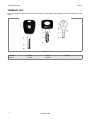
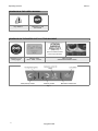
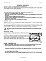
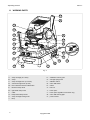
Operating Manual
Original Instructions
D443203XA
vers. 1.0
EN
(c) 2014 SILCA S.p.a. - Vittorio Veneto
This manual has been drawn up by SILCA S.p.a.
All rights reserved. No part of this publication can be reproduced or circulated by any means whatsoever (photocopies, microfilm or other)
without the consent of SILCA S.p.A.
Edition: January 2014
Printed at Vittorio Veneto
da SILCA S.p.a.
via Podgora, 20 (Z.I.)
31029 VITTORIO VENETO (TV) - Italy
The Manufacturer declines any responsibility for possible inaccuracies in this document due to printing or transcription errors. The Manufacturer reserves the right to alter the information without prior notice, except when they affect safety. This document or any of its parts cannot be
copied, altered or reproduced without written authorization from the Manufacturer. Keep the manual and look after it for the entire life cycle of the
machine.
The information has been drawn up by the manufacturer in his own language (Italian) to provide users with the necessary indications to use the
key-cutting machine independently, economically and safely.
IMPORTANT NOTE: in compliance with current regulations relating to industrial property, we hereby state that the trade-marks or trade names
mentioned in our documentation are the exclusive property of authorized manufacturers of locks and users.
Said trade-marks or trade names are nominated only for the purposes of information so that any lock for which our keys are made can be rapidly
identified.
INDEX
USE OF THE MANUAL ....................................................................................................................... 1
TERMINOLOGY ................................................................................................................................. 2
1 MACHINE DESCRIPTION....................................................................................................................5
1.1 WORKING PARTS ......................................................................................................................6
1.2 ACCESSORIES PROVIDED .....................................................................................................7
1.3 TECHNICAL DATA .....................................................................................................................7
1.4 ELECTRIC DIAGRAM ................................................................................................................8
2 HANDLING ...........................................................................................................................................9
2.1 PACKING ....................................................................................................................................9
2.2 TRANSPORT ..............................................................................................................................9
2.3 UNPACKING ...............................................................................................................................9
2.4 HANDLING THE MACHINE........................................................................................................9
3 MACHINE INSTALLATION AND PREPARATION ..............................................................................10
3.1 CHECKING FOR DAMAGE ......................................................................................................10
3.2 ENVIRONMENTAL CONDITIONS ............................................................................................10
3.3 POSITIONING ..........................................................................................................................10
3.4 SAFETY DEVICES ...................................................................................................................10
3.5 WORK STATION DESCRIPTION .............................................................................................11
3.6 STARTING THE KEY-CUTTING MACHINE .............................................................................12
3.6.1
STARTING THE MOTOR .....................................................................................................12
3.6.2
CUTTER MOTOR ON WARNING LIGHT.............................................................................12
3.6.3
LED LAMP ...........................................................................................................................12
4 MACHINE CALIBRATION AND REGULATION ..................................................................................13
4.1 FITTING AND REMOVING TOOLS ..........................................................................................13
4.2 MICROMETER GAUGE ...........................................................................................................14
4.3 CALIBRATION / TOOL ALIGNMENT ........................................................................................15
4.4 CARRIAGE SPRING FOR LASER KEYS ................................................................................17
4.4.1
REGULATING CARRIAGE SPRING FOR LASER KEYS ....................................................18
4.5 CLAMPS ..................................................................................................................................19
5 CUTTING ............................................................................................................................................20
5.1 FITTING KEYS .........................................................................................................................20
5.2 KEY STOP ................................................................................................................................20
5.3 CUTTING DIMPLE KEYS .........................................................................................................21
5.3.1
BACK CUTS .........................................................................................................................21
5.4 CUTTING LASER TYPE KEYS ................................................................................................22
5.5 CUTTING LASER KEYS WITH NARROW STEMS (MERCEDES) WITH ADAPTER “M” .......23
6 MAINTENANCE..................................................................................................................................24
6.1 TIGHTENING AND REPLACING THE BELT ............................................................................24
6.2 REMOVING THE UPPER FRONT UNIT ..................................................................................25
6.3 REPLACING THE ROLLBAR ...................................................................................................25
6.4 REPLACING THE TRANSPARENT SAFETY SHIELD .............................................................26
6.5 REPLACING THE LAMP ..........................................................................................................26
6.6 ADJUSTING/REPLACING THE VERTICAL CARRIAGE SPRING...........................................27
6.7 CHECKING AND REPLACING FUSES ....................................................................................28
6.8 REPLACING THE CALIBRATION KEY PAD ELECTRONIC CIRCUIT BOARD.......................29
6.9 REPLACING THE CONDENSER .............................................................................................29
6.10 REPLACING THE MOTOR .......................................................................................................30
6.11 REPLACING THE TRANSFORMER ........................................................................................30
6.12 REPLACING SWITCHES: MASTER AND MOTOR ON ...........................................................31
6.13 ALIGNING/CALIBRATING THE CLAMP...................................................................................32
6.13.1 CONTROL ALIGNMENT LEFT-HAND STATIONARY JAWS ...............................................32
6.14 REPLACING THE JAWS ..........................................................................................................33
6.14.1 REPLACING THE FIXED JAWS ..........................................................................................33
6.14.2 REPLACING MOBILE JAW ON LEFT-HAND CLAMP ........................................................34
6.14.3 REPLACING MOBILE JAW ON RIGHT-HAND CLAMP ......................................................34
7 DECOMMISSIONING .........................................................................................................................35
8 AFTER-SALES SERVICE ..................................................................................................................36
8.1 HOW TO APPLY FOR AFTER-SALES SERVICE ...................................................................36
Operating manual
Matrix II
USE OF THE MANUAL
This manual has been drawn up by the Manufacturer and is an integral part of the machine literature.
The manual gives information it is obligatory for the operator to know and which makes it possible to use the
machine safely.
• User’s Manual
This user’s manual is provided because it is essential for proper use and maintenance of the machine.
The manual must be kept carefully throughout the life of the machine, including the decommissioning stage. Keep
in a dry place close to the machine where it is always to hand for the operator.
IT IS OBLIGATORY to read the manual carefully before using the machine.
• Readers’ characteristics
This manual must be read and its contents acquired by those who will use it.
The MATRIX II key-cutting machine is designed for professional use by adults of either gender in full possession
of their physical, sensorial or mental capacities.
• Manufacturer’s ID
MATRIX II has an ID plate located on the back of the machine, showing the serial number.
Fig. 1
(*) See chap. 7 DECOMMISSIONING
• How to apply for after-sales service
Silca provides purchasers of MATRIX II with After-Sales Service.
For the total safety of the operator and machine, any operation not described in the manual must be carried out
by the manufacturer or in the special Service Centres recommended by Silca.
At the end of the manual there is a list of manufacturers’ and authorized Service Centre addresses.
The warranty card attached to the machine covers free repairs or replacement of faulty parts for 24 months from
the date of purchase*. All operations must be agreed by the user with Silca or the Service Centre.
* Damage caused by negligence or wrong use of the machine by the user will null the warranty.
1
Copyright Silca 2014
Operating manual
Matrix II
TERMINOLOGY
For those inexperienced in the subject of keys and key cutting, below is an illustration of the most frequently used
terms:
Fig. 2
1) Head
2) Neck
2
3) Stop
4) Stem
5) Tip
6) Back
Copyright Silca 2014
7) Cuts
Operating manual
Matrix II
GRAPHICS IN THE USER’S MANUAL
Pay attention
Obligation to read
the manual
GRAPHICS ON THE MATRIX II KEY-CUTTING MACHINE
(chap. 1.2)
place the adhesive label
in the way illustrated.
Obligatory use of
safety goggles
Adhesive label
Mass - RPM - Fusibles
Adhesive label
“DANGEROUS MOBILE PARTS”
Fig. 3
3
Copyright Silca 2014
Operating manual
Matrix II
GENERAL WARNINGS
MATRIX II is designed to the principles of European Standards (CE).
Right from the design stage solutions have been adopted to eliminate hazards for the operator in all the stages
of use: handling, regulation, use and maintenance.
The materials used in manufacture and the components employed in using MATRIX II are not dangerous and
ensure that the machine complies to current standards.
Silca S.p.A. has also experimented and applied numerous technical solutions that allow the key-cutting machine
to optimize the quality of the cut keys.
To guarantee maintaining these results over time, please follow the instructions below:
• Observe the procedures described in this manual;
•
Always use Original Silca Tools as they are designed to make the best of MATRIX II and provide quality
key-cutting;
•
Use Silca key blanks, made with top quality materials;
•
Have the key-cutting machine checked periodically by an authorized Silca After-Sales Service Centre
(list at the end of this manual).
•
Always use Silca Original Spare Parts. Beware of imitations!
NORMAL USE
MATRIX II is a key-cutting machine and must be installed and used according to the rules and specifications
established by the manufacturer.
The MATRIX II key-cutting machine is designed for use on business or industrial premises (e.g. hardware shops,
key cutting centres, etc...).
Any other use different from that indicated in this manual will cause the forfeiture of all customers’ rights to make
claims on Silca S.p.A. and may be an unknown source of hazard for the operator or third parties.
ATTENTION: negligent use or failure by the operator to observe the instructions in this manual
are not covered by the warranty and the manufacturer declines any responsibility in such
cases.
RESIDUAL RISKS
On the MATRIX II key-cutting machine there is a residual risk of injury in
the cutter spindle area (cutter rotating) if the vertical axis for laser cuts is
blocked.
Furthermore, the MATRIX II key-cutting machine has residual risks when
gaining access to parts in motion (not fully protected) and the risk of
chippings flying into the air during the key copying process.
These residual risks in the product are reported in special warnings
(“ATTENTION DANGEROUS MOBILE PARTS”) and involve the
obligatory use of personal protective devices (GOGGLES).
Fig. 4
SAFETY REGULATIONS
•
Always disconnect the machine when it is not in use or when performing maintenance operations.
•
Check the electrical wiring periodically; replace any wires that show signs of wear.
•
Always work with dry hands free of grease or oil.
•
Never pull hard on the power lead and make sure it does not come into contract with oil, sharp objects
or heat. Never remove the earth wire from the plug. Make sure the earth wire connection is sound.
•
Do not use the machine in dangerous environments (wet or damp).
•
All visitors, especially children, must stay at a safe distance from the machine and must never come
into contact with the electric wiring.
•
Place the adhesive label provided “DANGEROUS MOBILE PARTS” as shown in chap.3.3 POSITIONING.
4
Copyright Silca 2014
Operating manual
Matrix II
1 MACHINE DESCRIPTION
The MATRIX II key-cutting machine gives excellent technical performance of great precision.
The standard clamp on MATRIX II is used to cut some of the following types of keys:
• keys with flat dimple cuts
• keys with laser type cuts
• laser keys with a narrow stem (Mercedes) with “M” adapter
KEYS WITH DIMPLE CUTS
KEYS WITH LASER TYPE CUTS
LASER KEYS WITH A
NARROW STEM (MERCEDES)
with “M” adapter
(provided - see chap.1.2)
5
Copyright Silca 2014
Operating manual
Matrix II
1.1 WORKING PARTS
D1
D
V
K
G
R
T
J
C
F
E
W
B
P
H
Q
Z
E1
S
O
A
Fig. 5
A-
clamp carriage (X-Y axes)
K - calibration unit key pad
B - clamp
O - carriage spring knob
C-
clamp carriage lever (X-Y axes)
P-
D-
vertical carriage lever (Z axis)
Q - motor ON switch
ON/OFF switch
D1- lever release and motor start button
R - rollbar
E-
S - tool box
left-hand clamp knob
E1- right-hand clamp knob
T-
F-
V - tracer point regulation micrometric ring
cutter
tracer point
G - transparent safety shield
W-
motor ON warning light
H - clamp carriage locking knob
Z-
power socket
J -
6
lamp
Copyright Silca 2014
Operating manual
Matrix II
1.2 ACCESSORIES PROVIDED
MATRIX II comes with a series of accessories for use and maintenance (tools, hex wrenches, fuses, etc.) provided
in a special holder:
fuse (1 pc)
F22 cutter
500 mA rapid
T22 tracer point
fuse 2 pcs
6,3 Amp rapid (100V/120V)
Steel bar
2.5 (0.098”) hex wrench
Calibration pins
Adhesive label
“DANGEROUS
MOBILE PARTS”
MERCEDES “M” adapter
D910533ZR
1.3 TECHNICAL DATA
Power supply:
100V/120V - 50/60Hz - 2,3 Amp. - 220 Watt
Cutter motor:
single phase 1 speed motor 100V/120V 50/60Hz
Cutters:
Super speed steel
Tool speed:
6000 rpm (for cutters in super speed steel)
Movements:
on 3 axes by ball guides
Clamps:
fixed with interchangeable plates
Runs:
X axis: 40mm (1.574”) - Y axis: 50mm (1.967”) - Z axis: 30mm (1.18”)
Dimensions:
width: 310mm (12.19”) (maximum lever operating space 400mm 15.74”)
depth: 400mm (15.74”) - height:470mm (18.49”)
Illumination:
LED lamp
Mass:
Kg. 24,6
Noise rating:
Lp (A) = 70,5 dB (A) brass dimple keys
Lp (A) = 75,9 dB(A) brass keys with laser cuts
Lp (A) = 76,6 dB(A) steel keys with laser cuts
7
Copyright Silca 2014
Operating manual
Matrix II
1.4 ELECTRIC DIAGRAM
Fig. 6
1)
2)
3)
4)
5)
6)
7)
8
Fuses: 6,3 Amp (120V)
Safety switch
Terminal board
Motor ON/OFF switch
Motor 14 mF (100V/120V)
Motor warning light (LED)
Motor safety microswitch
8) Transformer
9) LED circuit
10) LED lamp
11) Tracer point contact
12) Cutter contact
13) Condenser
14) Fuse 500 mA - rapid
Copyright Silca 2014
Operating manual
Matrix II
2 HANDLING
The MATRIX II key-cutting machine is easy to handle and there are no special hazards involved in moving it.
The packed machine can by carried manually by one person.
2.1 PACKING
The packing for the MATRIX II key-cutting machine ensures safe handling of
the machine and all its components.
Packing comprises expanded plastic material wrapped around the machine.
The robust cardboard box in which it is placed and the nylon wrapping protect
the machine even when stored for a long period.
Fig. 7
Keep dry
Handle with care
Up
2.2 TRANSPORT
The symbols on the outside of the cardboard box give indications for transport.
ATTENTION: keep the complete packing for future machine transfers.
2.3 UNPACKING
To remove the machine from its packing:
1) Cut the strapping with scissors and remove.
2) Open the box carefully without damaging it.
3) Free the machine from the protective shells.
4) Check the contents of the packing, comprising:
- MATRIX II key-cutting machine.
- Documentation comprising: user’s manual, spare parts sheet, specialist guide and warranty.
- Power lead.
- Tool holder.
2.4 HANDLING THE MACHINE
Once removed from its packing place MATRIX II directly on the work bench; one person can easily perform this
operation.
ATTENTION: lift the machine by holding onto the base. Never lift the machine by gripping the
clamps, levers or other parts.
9
Copyright Silca 2014
Operating manual
Matrix II
3 MACHINE INSTALLATION AND PREPARATION
Installation is the customer’s task and does not require any special skills.
The key-cutting machine is supplied ready for use and does not need calibration except for the tools to be used;
however, the operator is required to make certain checks and prepare the machine for use.
3.1 CHECKING FOR DAMAGE
MATRIX II is a solid compact machine and will not break if handling, unpacking and installation are carried out
to the instructions in this manual. However, it is good practice to check that the machine has not been damaged.
3.2 ENVIRONMENTAL CONDITIONS
To make the most of the key-cutting machine, bear in mind the following environmental parameters: it is advisable
for the area to be dry with good air circulation.
The optimum environmental conditions for machine operation are:
- temperature 10° C to 40°C; - relative humidity: approx 60%.
3.3 POSITIONING
1) Place the key-cutting machine on a solid horizontal work bench suitable for the weight of the machine (24,6 Kg).
The work bench should be approximately 100-120cm (39.35”-47.22”) high to facilitate access to the working
parts. We recommend leaving at least 30cm (11.80”) clearance behind and around the machine to ensure good
ventilation and facilitate handling (Fig. 9).
2) Make sure machine voltage is suitable for the mains supply and that the latter is earthed with a differential
switch.
3) Place the adhesive label “DANGEROUS MOBILE PARTS” (provided) in the appropriate language in position as
shown in Fig. 8.
4) Connect the power lead to the machine (Fig. 10).
Fig. 8
Fig. 9
Fig. 10
3.4 SAFETY DEVICES
• ON/OFF master switch (P)
The master switch (P) is electromagnetic and turns the machine off automatically when power fails. When power
returns the switch must be reset manually to provide the machine with voltage.
• Push button (D1) to release the lever and start the motor
When push button (D1) is not activated there is no risk of involuntarily or accidentally moving the lever (D) and
preventing the motor from starting.
• Warning light (W) cutter motor on
The right-hand front part of the machine (behind the clamp unit) has a warning light (W). The warning light flashes
when the cutter motor is on.
10
Copyright Silca 2014
Operating manual
Matrix II
3.5 WORK STATION DESCRIPTION
The machine is operated by a single person using the following controls:
•
ON/OFF master switch (P) located on the righthand side of the machine.
D1
•
Motor ON/OFF switch (Q).
D
•
Vertical carriage lever (D) with push button (D1)
to release the lever and start the motor.
•
Clamp unit
•
Lever (left-hand) (C)
•
Key pad (calibration and illumination) (K)
K
C
P
Q
Fig. 11
• ORGANIZER SHELF (Z)
The top part of the cover incorporates an area for the operator to use as a place for things such as key blanks or
cut keys. It is advisable not to put too many things in this area, as they could accidentally fall off.
• ROLLBAR (R)
The purpose of this special bar is to assist the operator
during key cutting. It is used as a rest for the left hand
when moving the clamp carriage (centering cuts on
dimple keys or cutting path for laser keys). It ensures
smooth synchronised carriage movements during cutting
operations.
• TRANSPARENT SAFETY SHIELD (G)
Special plexiglass shield to limit the dispersal of swarf.
• TOOL BOX (S)
In the bottom part of the machine front, under the clamp
unit carriage, there is a tool box with an open part to use
as a handle for pulling out the box. Inside it has 20 spaces
for holding tracer points and cutters, and a larger area for
other small tools and/or keys.
Z
R
G
S
Fig. 12
11
Copyright Silca 2014
Operating manual
Matrix II
3.6 STARTING THE KEY-CUTTING MACHINE
1) Connect the power lead.
2) Turn on the key-cutting machine with the master switch (P). A beep sounds and for a second all the warning
lights (leds) on the key pad/control board (K) light up simultaneously on the machine front (blue vertical bar green vertical bar -2 red arrows) (Fig. 3).
3) When the beep stops only the blue warning light stays on to indicate that the machine is live.
Nota: if the conditions described above do not occur, see chap.6.7.
3.6.1
STARTING THE MOTOR
With the machine connected and on:
1) Press the luminous switch (Q) to power the motor (Fig. 11).
2) Press the push button (D1) on the vertical axis lever (D) and lower the lever.
ATTENTION: if the motor does not start and the lever (D) will not move, check that the lever is
fully tightened.
A flashing warning light (W) signals that the motor is on (chap.3.6.2). Attention: cutter in motion!
3) To turn off the motor release the lever (D) or turn off one of the 2 switches (P) or (Q).
3.6.2
CUTTER MOTOR ON WARNING LIGHT
There is a warning light (W) on the right-hand part of the machine
front (behind the clamps unit (Fig. 13).
When the cutter motor is on the warning light flashes.
W
Fig. 13
3.6.3
LED LAMP
When the key-cutting machine is turned on the lamp is off.
Lightly touch the button (J1) to turn the lamp on or off.
J1
Fig. 14
12
Copyright Silca 2014
Operating manual
Matrix II
4 MACHINE CALIBRATION AND REGULATION
Before carrying out cutting operations the clamps and tools must be regulated. According to the type of key to be
cut, activate or deactivate the spring device provided with the machine to facilitate cutting operations:
• cross spring for the carriage used for laser keys (chap.4.4 ).
4.1 FITTING AND REMOVING TOOLS
Fig. 15
ATTENTION: carry out this operation with the cutter motor off.
Lever (D) fully raised.
Clamp carriage lever (C) fully down.
Tracer point
Fitting:
- insert the tracer point all the way into the spindle with the numbered ring towards the clamp.
- hold the tool in this position and tighten the grub screw (G3) with the hex wrench provided.
Removing:
- loosen the grub screw (G3) with the hex wrench and remove the tool.
Cutter
Fitting:
- insert the cutter into the spindle with the numbered ring towards the clamp.
- hold the tool in this position and tighten the grub screw (G4) with the hex wrench.
Removing:
- loosen the grub screw (G4) with the hex wrench and remove the tool.
G3
G4
Fig. 16
13
Copyright Silca 2014
Operating manual
Matrix II
4.2 MICROMETER GAUGE
The micrometer gauge is used for tool alignment and also for
adjusting small variations in depths often necessary on worn
keys.
After tool alignment (green bar) the depth of cuts can be
reduced or increased by turning the micrometer gauge (V) to
the left or right.
Each line on the gauge corresponds to a displacement of
0,02mm (0.0007”).
V
Fig. 17
•
Turn the gauge clockwise to make cuts less
deep.
14
•
Turn the gauge anti-clockwise to make cuts
deeper.
Copyright Silca 2014
Operating manual
Matrix II
4.3 CALIBRATION / TOOL ALIGNMENT
Carry out this operation with the key-cutting machine on.
ATTENTION: check that the motor start switch (Q) is off.
1) Fit and secure the two tools (tracer point and cutter) in their respective spindles.
2) Press the button (K1) on the front of the machine to enable the key pad/control board.
Fig. 18
3) Press the lever (D) release button (D1), lower the vertical carriage and take the tools into contact with the clamp
surface (seat of the key) (Fig. 19). There are three possibilities:
• Central green bar illuminated - Green arrows illuminated - CALIBRATION OK
In this case both tools are in contact with the keys and aligned.
Nota: from this position it is advisable to turn the gauge (V) clockwise by a couple of clicks.
• Left-hand red arrow illuminated - Tracer point side
In this case only the tracer point is in contact with the key.
Hold the vertical carriage down and turn the gauge (V) anti-clockwise in the direction of the illuminated arrow.
Calibration is complete as soon as the green vertical bar illuminates together with the two green arrows.
• Right-hand red arrow illuminated - Cutter side
In this case only the cutter is in contact with the key.
Hold the vertical carriage down and turn the gauge (V) clockwise in the direction of the illuminated arrow so that
the red light on the left-hand arrow goes on. From this position hold down firmly the right-hand lever and turn the
gauge (V) one click at a time. Calibration is complete as soon as the green vertical bar illuminates together with
the two green arrows.
ATTENTION: at the end of calibration press the button (K1) to disable the key pad/control
board.
4) Now it’s possible to proceed with duplication.
15
Copyright Silca 2014
Operating manual
Matrix II
D1
V
D
Fig. 19
16
Copyright Silca 2014
Operating manual
Matrix II
4.4 CARRIAGE SPRING FOR LASER KEYS
The MATRIX II key-cutting machine comes with a spring system on the clamp carriage to control the range of
movement, considerably facilitating the cutting of laser keys.
The spring function for laser keys is activated by means of the knob (O) (Fig. 20) and causes pressure on the tool
sides along the cutting track when making cuts; this method allows the operator to trace cuts manually without
pressing crosswise with the lever (C). Fig. 21, Fig. 22 and Fig. 23 illustrate the three examples of use of the spring
system:
• CENTRAL cuts
•
RIGHT-HAND cuts
•
LEFT-HAND cuts
CENTRAL cuts
O
Fig. 20
Fig. 21
17
Copyright Silca 2014
Operating manual
Matrix II
RIGHT-HAND cuts
Fig. 22
LEFT-HAND cuts
D910533ZR
PROVIDED
Fig. 23
4.4.1
REGULATING CARRIAGE SPRING FOR LASER KEYS
With the motor power switch (Q) off, loosen the knob (O) slightly (Fig. 20).
• Central cuts:
Take the tools above the keys centred over the key stem (Fig. 21).
• Right-hand cuts:
Take the tools above the keys to the left of the key stem (Fig. 22).
• Left-hand cuts:
Take the tools above the keys to the right of the key stem (Fig. 23).
-
Lock the knob (O) and proceed with cutting.
18
Copyright Silca 2014
Operating manual
Matrix II
4.5 CLAMPS
Clamps come with easily replaced special key-locking jaws (B1) (B2) and (B3).
B1
B2
B1
B3
Fig. 24
KEYS WITH DIMPLE CUTS AND LASER KEYS
Fig. 25
19
Copyright Silca 2014
Operating manual
Matrix II
5 CUTTING
ATTENTION: Please see the following warnings to ensure completely safe cutting operations:
•
Always work with dry hands.
•
Check that the machine is earthed.
•
Wear the safety goggles even when the machine has a safety shield.
•
Start the motor only after completing the following operations:
fitting keys into the clamps
fitting and calibrating tools.
-
•
•
Keep your hands out of the way of the cutter in motion.
Cut the key only if calibration has taken place:
insert the necessary tools
turn on the key-cutting machine
proceed with calibration.
-
5.1 FITTING KEYS
1) Take the clamp carriage towards the operator until you feel the limit switch click.
2) Fit the original key into the left-hand clamp and the key to be cut into the right-hand clamp, paying attention to
the type of stop on the key.
3) Secure the keys with the knobs (E) (E1).
5.2 KEY STOP
The notches 0-1-2-3 on the clamp are used according to the type of key stop:
- 0: for keys with back stop (towards head - Fig. 26).
- 1-2-3: for keys with tip stop (Fig. 27)
Choice of stops 1 - 2 - 3 is determined by the length of the key stem.
ATTENTION: the cutting path must always lie within the clamp surface.
Fig. 26
Fig. 27
After fitting the keys into the clamps, follow the instructions for the type of key to be cut (chap.5.3 Cutting dimple
keys; chap.5.4 cutting laser type keys).
20
Copyright Silca 2014
Operating manual
Matrix II
5.3 CUTTING DIMPLE KEYS
1) Press the motor on switch (Q).
2) Insert the two keys into their clamps.
3) Take care when positioning the keys:
- Stop 0 for keys with stops.
- Stop 1 / 2 / 3 for keys without stops, using the bar provided for tip .
Attention: if the bar is used, remove it before making the cuts.
4) Grip the levers (C) and (D).
5) Press the button (D1) and lower the vertical carriage to start the motor.
6) Hold the carriage with the left-hand lever (C), lower the tool unit by means of the right-hand lever (D) until the
tracer point tip centres one of the holes. Continue to lower the lever (using the tracer point spring function) to
reach the cutting depth.
7) Repeat this operation for each hole on the key.
8) End cutting on the first side, release the lever (D) to stop the motor.
9) Remove the cut key only and place it on the second side (the key has the same cuts on both sides).
10)Proceed with cutting side 2.
0
Fig. 28
5.3.1
BACK CUTS
If there are cuts on the back of the key, stand it upright on the bottom of
the clamp (Fig. 29).
Fig. 29
21
Copyright Silca 2014
Operating manual
Matrix II
5.4 CUTTING LASER TYPE KEYS
1) Turn on the motor with the switch (Q).
2) Insert the two keys into their clamps.
3) Take care when positioning the keys:
- Stop 0 for keys with stops (chap. 5.2).
- Stop 1 / 2 / 3 for keys without stops, using the bar provided for tip stop (chap. 5.2).
Attention: if the bar is used, remove it before making the cuts.
4) Grip the levers (C) and (D).
5) Press the button (D1) and lower the vertical carriage to start the motor.
6) Keep the clamp carriage still with the left-hand lever (C) and lower the tool unit by means of the right-hand lever
(D) until the tracer point reaches the cutting depth.
7) Without exerting pressure, turn the lever (D)
clockwise to lock the height reached.
8) Move the lever (C) to trace all the cuts on the key with
D
the tracer point.
• For right-hand cuts it is advisable to make the
cuts by moving the tracer point from the head to
the tip.
•
For left-hand cuts it is advisable to make the cuts
by moving the tracer point from the tip to the
head.
9) When side 1 has been cut, turn off the motor with the
switch (Q).
10)Remove the key blank only and turn it 180° to cut side
2. The key has the same cuts on both sides.
11)Start the motor with the switch (Q) and make the cuts.
Fig. 30
Fig. 31
22
Copyright Silca 2014
Operating manual
Matrix II
5.5 CUTTING LASER KEYS WITH NARROW STEMS (MERCEDES) WITH ADAPTER “M”
Another function of the clamp is to cut laser keys with narrow stems by fitting the adapter M (provided). Follow
the instructions below:
1) Open the clamps by loosening the knobs (E) (E1).
Silca ref. HU41P, HU64P, HU64T - HU81T:
2) Fit the adapter onto the left-hand clamp and align the groove with the one on the clamp for “Stop 2” (Fig. 33)
Silca ref. HU55P:
3) Fit the adapter onto the left-hand clamp and align the groove with the one on the clamp for “Stop 3” (Fig. 34).
4) Slide the stop bar into the groove.
5) Insert the key and take it right up against the bar.
6) Secure adapter and key by tightening the knob (E).
7) Remove the bar and repeat the same operation on the right-hand clamp.
Cutting:
8) Grip the levers (C) and (D).
9) Press the button (D1) and lower the vertical carriage to start the motor.
10)Hold the clamp carriage still with the left-hand lever (C) and lower the tool unit with the right-hand lever (D) until
the tracer point touches the depth of the cut.
11)Without exerting pressure, turn the lever (D) clockwise to block the height.
12)Move the lever (C) to trace all the cuts on the key with the tracer point.
• For left-hand cuts we advise tracing the cuts by taking the tracer point from the tip to the head.
13)When the first side has been cut, turn off the motor with switch (Q).
14) Remove the key blank only and turn 180° to cut the second side. The key has the same cuts on both sides.
15) Re-start the motor with switch (Q) and proceed with cutting.
code D910533ZR
(PROVIDED)
Fig. 32
23
HU41P - HU64P - HU64T - HU81T
HU55P
Fig. 33
Fig. 34
Copyright Silca 2014
Operating manual
Matrix II
6 MAINTENANCE
ATTENTION: when repairing or replacing parts the “CE” label is guaranteed only if original
spare parts provided by the manufacturer are used.
The MATRIX II key-cutting machine does not need special maintenance, but it is good practice to check and if
necessary replace parts subject to wear: belts, lamp and vertical carriage spring.
Replacement operations are simple and can be performed by the operator.
CLEANING: it is advisable to keep the carriage and clamps clean by regularly brushing away the swarf deriving
from cutting operations.
ATTENTION: DO NOT USE COMPRESSED AIR!
ATTENTION: to maintain machine efficiency we recommend using protective oil such as
WD40 or similar to apply to the burnished mechanical parts. This will prevent oxidation of the
parts in question (clamps, guides, carriages...). Make sure the oil does not come into contact
with the electronic parts.
Before performing any type of maintenance (checks or replacements) read the warnings below:
• Do not perform any maintenance operations with the machine on.
•
Always disconnect the power lead.
•
Follow the instructions in the manual carefully.
•
Use original spare parts.
6.1 TIGHTENING AND REPLACING THE BELT
If vibrations occur on the top part of the key-cutting machine, check the state and tightness of the belt in the way
described:
1) Turn off the master switch and disconnect the power lead.
2) Loosen the 6 screws (Y1) and remove the top safety guard (Y).
3) Loosen (without removing) the 4 allen screws (Y2) securing the motor (Fig. 36).
Y
Y1
Y1
Fig. 35
Y2
Fig. 36
24
Copyright Silca 2014
Operating manual
Matrix II
Tightening:
Increase belt tension by pushing the motor towards the back of the machine.
Replacing:
1) Loosen the belt by pushing the motor gently towards the tracer point and cutter.
2) Remove the belt and replace.
3) Tighten by pushing the motor towards the back of the machine.
• secure the motor by tightening the 4 allen screws (Y2).
•
replace the top safety guard (Y) and secure with the 6 screws (Y1).
Fig. 37
6.2 REMOVING THE UPPER FRONT UNIT
1) Switch the machine off and disconnect the power lead.
2) Remove the 2 screws (R1) securing the rollbar (Fig. 38).
3) Loosen the 4 screws (K2) securing the upper front unit (K5) and remove.
6.3 REPLACING THE ROLLBAR
1)
2)
3)
4)
5)
Remove the upper front unit (K5) (chap6.2).
Loosen the 3 screws (R3) and remove the rollbar (R) (Fig. 39).
Fit the new rollbar and secure with the 3 screws (R3).
Replace the upper front unit on the machine and secure with the 4 screws (K2).
Secure the rollbar with the 2 screws (R1).
25
Copyright Silca 2014
Operating manual
Matrix II
6.4 REPLACING THE TRANSPARENT SAFETY SHIELD
1)
2)
3)
4)
5)
Remove the upper front unit (chap6.2).
Use a screwdriver to detach the shield from the upper front unit.
Attach the new shield to the upper front unit.
Replace the cover on the machine and secure with the 4 screws (K2).
Secure the rollbar with the 2 screws (R1).
R1
R1
K2
K2
Fig. 38
Fig. 39
6.5 REPLACING THE LAMP
Follow the instructions below to replace the lamp:
1) Remove the upper front unit (chap6.2).
2) Disconnect the connector (J4) (Fig. 40).
3) Loosen and remove the 2 screws (J1) securing the lamp glass (Fig. 41).
4) Loosen and remove the 2 screws (J3) securing the LED board.
5) Pull the LED lamp downwards.
6) Fit the new LED board so that the wire passes over the top and connect the connector to the board.
7) Secure the new board with the 2 screws (J3).
8) Secure the lamp glass with the 2 screws (J1).
9) Connect the connector (J4).
10)Replace the upper front unit on the machine and secure with the 4 screws (K2).
11)Secure the rollbar with the 2 screws (R1).
J3
J1
Fig. 40
26
Fig. 41
Copyright Silca 2014
Operating manual
Matrix II
6.6 ADJUSTING/REPLACING THE VERTICAL CARRIAGE SPRING
If the vertical carriage (Z axis) seems loose it is advisable to adjust the spring and replace if necessary. Proceed
as follows:
1) Switch off the machine and disconnect the power lead.
2) Remove the 6 screws (Y1) to detach the top safety guard (Y) (Fig. 35).
3) Loosen the 4 screws (Y3) and remove the rear panel (Fig. 42).
4) Turn the machine so that its back faces the operator.
To increase spring tightness:
- perform operations 1 and 2 shown in Fig. 44.
To decrease spring tightness:
- perform operations 1 and 2 shown in Fig. 45.
5) Replace the safety guard (Y) and secure with the 6 screws (Y1) (Fig. 35).
To replace the spring:
- follow the instructions in points 1. 2. 3.
- replace the spring and adjust tightness.
Y3
Fig. 42
Fig. 43
27
Fig. 44
Copyright Silca 2014
Fig. 45
Operating manual
Matrix II
6.7 CHECKING AND REPLACING FUSES
Fuses should be checked with an instrument for measuring continuity (tester, ohmeter, multimeter, etc.) as they
may appear normal to the eye even when electrically damaged. Each fuse must be replaced with one of the same
value (Amperes) and type (rapid or delayed), as shown in the manual. The MATRIX II key-cutting machine has:
2 fuses:
6,3 Amperes rapid on the 100V/120V key-cutting machine
Located in the mains socket, they protect the machine from
voltage variations and possible short circuits.
If the machine does not go on when the switch is activated,
it is advisable to check the fuses in the way described:
1) Turn off the machine with switch (P) and disconnect
the power lead.
2) Use a screwdriver to remove the fuses.
Fig. 46
1 fuse:
500 mA rapid
situated on the terminal board, it protects the calibration keypad circuit board from possible short circuiting. Check
the fuse when the blue LED does not illuminate with the machine on (circuit board not powered).
Follow the instructions below:
1) Turn off switch (P) and detach the power lead.
2) Place the key-cutting machine on its back and loosen the 4 screws (P4) to remove the bottom safety plate (Fig.
54).
3) Take the fuse out of its seat (V3) (Fig. 47 and Fig. 48).
4) Replace and secure the bottom safety plate with the 4 screws (P4).
5) Return the key-cutting machine to its proper position.
Fig. 47
28
Fig. 48
Copyright Silca 2014
Operating manual
Matrix II
6.8 REPLACING THE CALIBRATION KEY PAD ELECTRONIC CIRCUIT BOARD
If the key pad (K) is not working properly replace the electronic circuit board inside it as described below:
1) Remove the upper front unit (chap6.2).
2) Detach the connectors (J4) and (R4) (Fig. 49).
3) Remove the 4 screws (a) (b) (c) (d) paying attention to the position of the wires.
4) Remove the 2 screws (K4) fixing the circuit board.
5) Replace the circuit board, secure with the 2 screws and re-connect the 2 connectors (J4) and (R4) and the 4
wires with screws (a) (b) (c) (d).
6) Replace the upper front unit on the machine and secure with the 4 screws (chap6.2).
7) Secure the rollbar with the 2 screws (R1) (chap6.3).
Fig. 49
6.9 REPLACING THE CONDENSER
1)
2)
3)
4)
5)
6)
7)
8)
Switch off the machine and disconnect the power lead.
Loosen the 6 screws (Y1) and remove the top cover (Fig. 35).
Move the protective cap on the condenser (Fig. 51).
Disconnect the connectors from the condenser, paying attention to their position.
Loosen the condenser fixing nut (C3).
Connect the connectors to the new condenser and replace the protective chap.
Secure the condenser with the nut (C3).
Replace the top cover and tighten the 6 screws (Y1).
C3
Fig. 50
29
Fig. 51
Copyright Silca 2014
Operating manual
Matrix II
6.10 REPLACING THE MOTOR
1)
2)
3)
4)
5)
6)
7)
8)
Disconnect the key-cutting machine from the mains.
Loosen the 6 screws (Y1) and remove the top cover (Fig. 35).
Loosen the 2 screws (W1) fixing the motor wires to the terminal board and the screw on the earth wire (W2).
Loosen the 4 screws (Y2) securing the motor.
Remove the motor pulley belt.
Loosen the grub screw (P2) securing the motor pulley and pull upwards to remove (Fig. 53).
Grip the motor with one hand and use the other to loosen and remove the 4 screws (Y2).
Pull the motor out from back of the machine.
P2
Fig. 52
Fig. 53
6.11 REPLACING THE TRANSFORMER
1) Disconnect the power lead from the machine.
2) Turn the key-cutting machine on its back and loosen the 4 screws (P4) to remove the bottom safety guard (Fig.
54).
3) Loosen the 2 screws (Z2) fixing the low voltage (transparent) cables (20V) (Fig. 55).
4) Loosen the 2 screws (Z3) fixing the mains supply wires (a wire in position 0 and a wire corresponding to the
voltage being used).
5) Loosen the 4 screws (T3) securing the transformer and remove.
6) Install and secure the new transformer with the 4 screws (T3).
7) Use the screws (Z2) to fix the 2 transparent low voltage cables in the 12 Volt connectors on the transformer.
8) Secure the 2 mains supply wires to the connectors on the transformer (a wire in position 0 and one
corresponding to the voltage being used), with their screws (Z3).
Take care that the position is correct according to the voltage (Fig. 55).
9) Replace and secure the bottom safety guard with the 4 screws (P4).
10)Return the key-cutting machine to the upright position.
30
Copyright Silca 2014
Operating manual
Matrix II
P4
Fig. 54
Fig. 55
6.12 REPLACING SWITCHES: MASTER AND MOTOR ON
1) Disconnect the power lead from the machine.
2) Turn the key-cutting machine onto its back and loosen the 4 screws (P4) to remove the bottom safety guard
(Fig. 54).
3) Disconnect the wires from the switch to be replaced, paying attention to their position.
4) Press the fixing “tabs” on the switch so that it can be pulled out.
5) Insert the new switch into the special seat.
6) Reconnect the connectors.
7) Replace and secure the bottom safety guard with the 4 screws (P4).
8) Return the key-cutting machine to the upright position.
Fig. 56
31
Fig. 57
Copyright Silca 2014
Operating manual
Matrix II
6.13 ALIGNING/CALIBRATING THE CLAMP
The key-cutting machine comes from Silca with the clamp perfectly aligned. Alignment is necessary only if a jaw
has to be replaced.
1) Make sure the motor ON switch is OFF.
2) Fit and secure the 2 calibrating pins (provided) to the 2 spindles as if they were tools. N.B.: the flat part (with
greater diameter) must be visible (towards the clamp).
3) Turn on the key-cutting machine with the master switch (P).
4) Enable the key pad /calibration control board with key (K1).
D
Fig. 58
6.13.1
Fig. 59
CONTROL ALIGNMENT LEFT-HAND STATIONARY JAWS
1) Lower the vertical carriage with the lever (D) (Fig. 59).
2) Align the 2 pins on the key surface (chap4.3).
3) When the pins are aligned, raise them slightly with the lever (D) so that they are not in contact with the key
surface.
4) Turn the lever (D) clockwise to lock the height of the vertical carriage.
5) Move the clamp carriage with the lever (C) and take the pins into contact with several points on the left-hand
jaw (also on the side of Stop 0). If the calibration board shows a green light the fixed-hand jaws are aligned.
6) If not, loosen the 2 screws (B7) and regulate the jaw (if necessary, loosen the 2 nuts (B4) and regulate the 2
grub screws B5) until the condition described above is achieved.
Fig. 60
32
Copyright Silca 2014
Operating manual
Matrix II
B6
B5
B4 B7
B6
B5
B4 B7
Fig. 61
6.14 REPLACING THE JAWS
Make sure the motor ON switch is OFF.
6.14.1
1)
2)
3)
4)
REPLACING THE FIXED JAWS
Loosen the 2 screws (B6) or (B7) and remove the jaw.
Fit the new jaw up against the left-hand side and align also from the front (Fig. 63).
Tighten the 2 screws (B6) or (B7) without exerting pressure.
Check alignment (chap.6.13.1) and then fully tighten the screws (B6) or (B7).
Fig. 62
33
Fig. 63
Copyright Silca 2014
Operating manual
6.14.2
1)
2)
3)
4)
5)
Matrix II
REPLACING MOBILE JAW ON LEFT-HAND CLAMP
Fully unscrew the knob (E).
Loosen the 2 screws (H3) and remove the plate (H4) (Fig. 64).
Remove the mobile jaw and clean the clamp (Fig. 65).
Fit the new jaw and then screw in the knob.
Replace the plate (H4) and tighten the 2 screws (H3).
H3
H4
E
Fig. 64
6.14.3
1)
2)
3)
4)
5)
Fig. 65
REPLACING MOBILE JAW ON RIGHT-HAND CLAMP
Fully unscrew the knob (E1).
Loosen the 2 screws (U3) and remove the plate (U4) (Fig. 66).
Remove the mobile jaw and clean the clamp (Fig. 67).
Fit the new jaw, replace the plate (U4) and tighten the 2 screws (U3).
Screw in the knob (E1).
U3
E1
U4
Fig. 66
34
Fig. 67
Copyright Silca 2014
Operating manual
Matrix II
7 DECOMMISSIONING
To decommission the machine it must be made unusable by:
• deactivating the power supply;
• separating the plastic parts from the metal parts;
After doing the above, dispose of the waste in compliance with the current directives in the country where the
machine is located.
Waste disposal
CEE regulations lay down special methods for disposing of waste (**).
Machine
MATRIX II is not only a durable machine, but is also re-usable.
Recycling is a good environmentally friendly practice.
Packing
The MATRIX II device is consigned in a cardboard packing box which can be re-used if undamaged. When it is
to be thrown away it is classified as solid urban waste and should be placed in the special paper collecting bins.
The protective shell containing the machine is in expanded polyethylene, classified as SUW, and can therefore
be placed in an ordinary waste.
Waste from key-cutting
Residue deriving from key cutting is classified as special waste, but can be included in solid urban waste (SUW)
as metaI scourers. This waste must be disposed of in the special collection centres according to its classification
by current laws in Italy and the European Union. If it is contaminated or contains harmful-noxious substances
which transform the metal residue included in SUW into harmful-noxious substances, it is included in the lists of
the appendices to current regulations in Italy and the European Union for waste disposal.
INFORMATION TO USERS
Under the terms of art. 10 of Directive 2002/96/CE dated 27/01/2003
regarding waste from electric and electronic equipment (WEEE),
•
The symbol shown above is also attached to equipment and indicates that it has been placed on the market
and must be separated and disposed of when no longer wanted (including all components, sub-assemblies
and consumables that are an integral part of the product).
•
Please contact SILCA S.p.A. or any other subject on the national registers of other countries in the European
Union for information about waste disposal systems for the equipment. Household waste (or of similar origins)
can be disposed of by the separate urban waste collection system.
•
When purchasing new equipment of an equivalent kind the unwanted equipment can be given back to the
dealer. The dealer will then contact the authority responsible for collecting it.
•
Separate waste collection of unwanted equipment and its forwarding to treatment, recovery and environmentally
friendly disposal makes it possible to avoid potential negative effects on the environment and human health,
and assists recycling and recovery of materials.
•
Unauthorized disposal of the product by the user is punished by the application of fines established by the
countries which have received Directives 91/156/CE and 91/689/CE.
(**) wastes are substances or objects deriving from human activity or natural cycles which are discarded, or intended to be discarded.
35
Copyright Silca 2014
Operating manual
Matrix II
8 AFTER-SALES SERVICE
Silca provides full service to purchasers of the MATRIX II machine. To ensure total safety for the operator and the
machine, any operations not specifi ed in this manual shall be carried out by the manufacturer or in the special
Service Centres recommended by Silca.
On the back cover of the manual there is a list of the manufacturer’s addresses; the following page lists the
addresses of specialized Service Centres.
8.1 HOW TO APPLY FOR AFTER-SALES SERVICE
The warranty attached to the MATRIX II machine guarantees free repairs or replacement of faulty parts within 24
months of purchase. Any other operation shall be agreed by the user with Silca or its Service Centres.
36
Copyright Silca 2014
SILCA S.p.A.
Via Podgora, 20 (Z.I.)
31029 VITTORIO VENETO (TV)
Tel. 0438 9136 Fax 0438 913800
E-mail: [email protected]
www.silca.biz
In North America
Kaba Ilco Corp.
400 Jeffreys Road
Rocky Mount, NC 27804
Tel. 800-334-1381
Fax 252-446-4702
E-mail: [email protected]
www.kaba-ilco.com