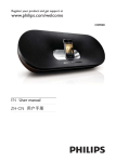
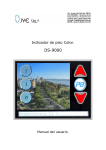
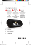
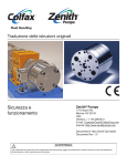
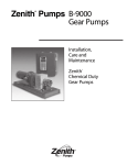
1
TO GET ASSISTANCE, CALL: 919-774-7667
ZENITH PUMPS
Page
Date: 04/2009
Zenith DS9000 Dispensing System
Installation & Operation Manual
ZENITH PUMPS
TO GET ASSISTANCE, CALL: 919-774-7667
ZENITH PUMPS
Page 2
Table of Content
Introduction............................................................................................... 3
Control Specification ................................................................................ 4
Wiring Diagram ........................................................................................ 5
Wiring Instructions................................................................................... 6
Field Wiring .............................................................................................. 7
Connect Input Power .............................................................................................7
Connect Stepper Motor..........................................................................................7
Connect Remote Control Signals ...........................................................................8
Program Loading ...................................................................................... 9
System Setup ............................................................................................10
System Status ...........................................................................................11
Operations................................................................................................12
Dispensing Mode.................................................................................................13
Dispensing Batch Mode .......................................................................................13
Dispensing & Reverse Mode ................................................................................14
Dispensing & Reverse Batch Mode.......................................................................15
Continuous Operation Mode................................................................................16
Customer Programming & Support........................................................17
TO GET ASSISTANCE, CALL: 919-774-7667
ZENITH PUMPS
Page 3
Introduction
This manual contains information required to complete installation, wiring, and startup operation for Zenith DS9000 Dispensing Control System.
Be sure to follow all WARNINGS, CAUTIONS, and NOTES prior to proceeding with a particular task.
Customer is required to make field wiring connections and adjust some parameters dependent
NOTE: on specific applications.
Customer should become familiar with this manual to avoid electromagnetic interference (EMI)
noise pickup, damage to equipment, and personal injury.
WARNINGS:
•
Do not mount Zenith Dispensing Control System near heat-radiating elements or in direct
sunlight.
•
Do not install Zenith Dispensing Control System in a place subjected to high temperature,
high humidity, excessive vibration, corrosive gases or liquids, or airborne dust or metallic
particles.
•
Mount Zenith Dispensing Control System vertically and do not restrict the air flow to the
drive.
•
Allow sufficient space around the unit for heat dissipation. Approximately 6 inches should be
allowed above and below the drive and 2 inches on each side.
ZENITH PUMPS
TO GET ASSISTANCE, CALL: 919-774-7667
Page 4
Control Specification
Unit
Rated Input Voltage
Rated Input Frequency
Input Voltage Range
Output Current
DC Bus Voltage
VAC
Hz
VAC
A
VDC
Power
115 / 230, 1 Phase
60/50
94 ~ 264
0.5 ~ 3.2 Peak
165 Nominal
Operation Interface
4.7” LCD touch screen, 256 color, with backlight
Control Interface
English (can support Spanish, German, French, Italian, Turkish, Korean, Chinese, Japanese)
Languages
Input / Output
2 High Speed Inputs: 5VDC (STEP, DIR)
5 Standard Digital Inputs: 12/24VDC (Enable, Alarm Reset, CW Limit, CCW Limit)
3 Digital Outputs: 5~24VDC (Brake, Motion, Fault)
1 Analog Input: ±10VDC
6 Digital Inputs: 24VDC (RUN, STOP, Dispensing, Dispensing & Reverse, Continuous)
3 Digital Outputs: 5~24VDC
Drive Digital Inputs
Drive Digital Outputs
Drive Analog Input
PLC Digital Inputs
PLC Digital Outputs
Protection
Over-voltage, Under voltage, Over-temperature, External Output Shorts (Phase-to-Phase,
Phase-to-Ground), Internal Amplifier Shorts
Reduction to any integer percent of full-current after delay
Build in regeneration circuit—25W max.
Protection
Idle Current Reduction
Motor Regeneration
Diagnostic
Bi-color Status Light
LED Lights for Inputs and Outputs
Drive Status
PLC Status
Programming & Communication
Zenith® Dispensing System
PLC Programming Software (optional), Touch Screen Programming Software (optional)
RS232
Preloaded Software
Programming Software
Communication
Environment
Environment
Drive Ambient
Motor Ambient
Motor Insulation Class
Storage
Relative Humidity
Cooling
˚C
˚C
˚C
˚C
IP65, Dust-proof and drip-proof
0˚C ~ 55˚C
0˚C ~ 50˚C
130˚C Class B
-20˚C ~ 60˚C
Maximum 90% at 25˚C, Non-condensing
Natural, air cooled
Certification
NEMA Ratings
Classifications:
NEMA 4/12
UL/cUL
ZENITH PUMPS
TO GET ASSISTANCE, CALL: 919-774-7667
Page 5
Wiring Diagram
Zenith Dispensing Control Cabinet
AC Power Input
115/230 VAC
1PH
(94~264VAC)
Motor Connection
Connector
Supplied
Customer Signals
Optional
Remote
Signals
L
N
GND
White
A+
Green
A-
Red
B+
Black
B-
Shield
SHLD
Dispensing Remote
X0
RUN (optional)
Disp. & Reverse Remote
X1
RUN (optional)
Continuous
X2
RUN (optional)
Remote STOP
X5
(optional)
Remote Signal COM
COM
(optional)
Motor
Controller
Unit
PLC
Unit
TO GET ASSISTANCE, CALL: 919-774-7667
ZENITH PUMPS
Page 6
Wiring Instructions
Zenith Dispensing Control System requires customers to wire to the terminal strips in the control cabinet.
TO PREVENT PERSONNEL ELECTROCUTION OR DAMAGE TO THE EQUIPMENT,
CAUTION: MAKE SURE ALL POWER TO DISPENSING CONTROL SYSTEM IS REMOVED BEFORE MAKING ANY WIRING CONNECTIONS OR CHANGES.
Wiring practices must conform to applicable local electric codes and the National Electric Code (NEC).
If installed in a country outside USA, wiring practices should conform to the electric codes of the country
Zenith Dispensing Control System is installed in.
•
Input power to the control cabinet must be supplied through an appropriately sized circuit
breaker or fused disconnect that is within easy reach of control cabinet.
•
Control cabinet ground must be a single point termination and be at a resistance of less than
1 ohm with relation to true earth. All grounds within control cabinet must be connected to
the single point ground termination.
•
High voltage wiring (> 50 V) must be run in separate conduit from low voltage (<50 V) or
signal wiring. If run parallel to each other, high voltage wiring should be separated from low
voltage and signal wiring by 12 inches or as much as physically possible. If they must cross
each other, they should cross perpendicularly.
•
Shielded cable should be used for signal wiring to prevent electrical noise contamination.
The shield should be terminated at Zenith Dispensing Control System only. (NOTE: Terminating the shield at both ends causes ground loops and defeats the purpose of using
shielded cable).
•
Low voltage wiring making long runs outside a control cabinet should use shielded cable
also. Shield termination should be at the end of the cable connected to the equipment requiring the most noise protection. (NOTE: In some cases, this may be the PC or PLC, rather
than Zenith Dispensing Control System ).
ZENITH PUMPS
TO GET ASSISTANCE, CALL: 919-774-7667
Page 7
Field Wiring
1. Connect Input Power
WARNING:
ALWAYS UNPLUG LINE CORD FROM THE WALL BEFORE ATTACHING IT
TO THE CONTROL CABINET!
Customer supplies input AC power.
The controller supports 115/230VAC single phase, all you need to do is install a power cord and
plug it in 115/230VAC single phase power source.
•
Install A Power Cord
−
−
−
−
Remove 5 mm (3/16”) of insulation from each wire of a power line cord.
Connect black wire to “L” terminal on PLC in control cabinet
Connect white wire to “N” terminal on PLC in control cabinet
Connect green wire to “G” terminal on PLC in control cabinet
2. Connect Stepper Motor
WARNING:
NEVER CONNECT MOTOR TO CONTROL CABINET WHEN AC POWER IS ON
ALWAYS SECURE ANY UNUSED MOTOR LEADS
NEVER DISCONNECT MOTOR WHILE AC POWER IS ON
NEVER CONNECT MOTOR LEADS TO GROUND OR TO A POWER SUPPLY
•
Standard Motor — 4-Lead Stepper Motor
Zenith Dispensing Control System uses a 4-lead motor.
Connect 4 wires of the motor cable based on the diagram
shown at right.
A+
A-
WHITE
4
Lead
Motor
GREEN
RED
BLACK
B+
•
6-Lead Stepper Motor
These motors can be connected in series or center
tap.
Note: NC means not connected to anything.
A-
B-
A6
Lead
Motor
NC
6
Lead
Motor
A+
A+
NC
B-
NC
B+
Series Connection
B-
B+
NC
Center Tap Connection
ZENITH PUMPS
TO GET ASSISTANCE, CALL: 919-774-7667
Page 8
Field Wiring (cont’d)
•
8-Lead Stepper Motor
A+
A+
These motors can be connected in two ways: series and
parallel.
Note: NC means not connected to anything.
8
Lead
Motor
8
Lead
Motor
A-
A-
B+
B-
Series Connection
B+
B-
Parallel Connection
3. Connect Remote Control Signals (Optional):
Zenith Dispensing Control System supports remote signal controls, such as Dispensing Remote
Run, Dispensing & Reverse Remote Run, Continuous Remote Run, and Remote Stop. The remote
control signal common is 0VDC, and these remote signals should be 24VDC (at least 21.6VDC).
To make connections, connect the remote signal wires to corresponding terminals on PLC unit in
control cabinet as shown in the following diagram:
WARNING:
MAX. VOLTAGE THAT CAN BE APPLIED TO AN INPUT TERMINAL IS 26.4 VDC
NEVER APPLY AC VOLTAGE TO AN INPUT TERMINAL
MAXIMUM CURRENT IS 8mA PER INPUT
TO GET ASSISTANCE, CALL: 919-774-7667
ZENITH PUMPS
Page 9
Program Loading
Zenith Dispensing System control software should be preinstalled before shipment.
Whenever the control program has to be loaded unto the system, the software FPWIN PRONOTE 1 for PLC
control program, and GTWINNOTE 1 for touch screen interface program, are needed. Additionally, STAC6
ConfiguratorNOTE 1 may also be needed for configuring stepper motor drive in the control cabinet.
To use FPWIN PRO and GTWIN, please follow:
•
Install Zenith Dispensing System
•
Connect any inputs or outputs that the process may require
•
Connect the programming cable between RS232 serial communication port on a PC and
Tool Port at the back of the touch screen
•
Install FPWIN PRO and GTWIN on PC
•
Connect and apply power to Zenith Dispensing System
•
Use GTWIN to open Zenith touch screen interface program
•
To download Zenith touch screen interface program, select “File” - “Transfer” and the following window will show up. On this window, make sure to select “All Data” and “GTWIN>GT”, and click “OK” button. Wait until the screen data has been completely transferred to
the touch screen
•
Use FPWIN PRO to open Zenith Dispensing control program
•
To download Zenith Dispensing control program, select “Online” - “Download Program
Code and PLC Configuration”.
——————————————————————————————————————————————NOTE 1
Software has to be ordered separately from the system.
TO GET ASSISTANCE, CALL: 919-774-7667
ZENITH PUMPS
Page 10
System Setup
System Setup screen can be accessed by clicking “System Setup” button at lower right corner of Main
Control screen.
Zenith Dispensing System has to be properly configured, immediately after the system is installed, and
before any tests and operations are performed.
System Setup screen includes the following parameters:
•
Pump Capacity (cc/rev), input range: 0.001-100.0, default: 2.4
•
Max. Pump Speed (rpm)*, input range: 0-600, default: 300
•
Accel/Decel Time (sec), input range: 0.01-600.0, default: 1.0
•
Pump Direction (facing pump shaft), selection: CCW / CW, default: CCW
•
Operation Control Method, selections: Keypad / PLC Remote, default: Keypad
WARNING:
SYSTEM HAS TO BE PROPERLY CONFIGURED, IMMEDIATELY AFTER THE SYSTEM IS INSTALLED, AND BEFORE ANY TESTS AND OPERATIONS ARE PERFORMED.
TO GET ASSISTANCE, CALL: 919-774-7667
ZENITH PUMPS
Page 11
System Status
Status screen can be accessed by clicking “STATUS” button at bottom of Main Control screen and each
dispensing operation screen.
System Status screen shows the following status of Zenith Dispensing System:
•
In Operation
•
Drive Fault
•
PLC Self Diagnosis Error
•
PLC Operation Error
•
PLC Battery Error
•
PLC Voltage Dip
•
PLC Fuse Blow
•
PLC Output Enable
•
Battery (Hold) Error
TO GET ASSISTANCE, CALL: 919-774-7667
ZENITH PUMPS
Page 12
Operations
Zenith Dispensing System is shipped with interface/control program pre-installed unto the nonvolatile
memory inside of PLC and touch screen.
The control program supports five typical fluid delivery applications: dispensing, batch dispensing, dispensing and reverse, batch dispensing and reverse, and continuous dispensing.
Install Zenith pump system, and follow the installation instructions in “Fielding Wiring” on page 7 to set
up the control system. The interface/control program will be loaded automatically once the power is
applied to the system. The basic operation procedures are:
•
At power up, the following information screen is displayed
•
After about three seconds of power up, the Main Control screen will be displayed as follow
•
Select the desired fluid delivery applications by touching corresponding button on the touch
screen
•
On each fluid delivery control screen, input the required parameters by clicking each parameter field. A numeric keypad will be shown on the screen when a parameter field is
touched. Input value for this parameter, and click “DONE” to go back to the control screen
•
To initiate operation, click “RUN” button on the touch screen
•
To stop operation, click “STOP” button on the touch screen
•
To check the status of the system, click “STATUS” button on the touch screen
•
To obtain help for each screen, click the title showing on the touch screen
TO GET ASSISTANCE, CALL: 919-774-7667
ZENITH PUMPS
Page 13
Operations (cont’d)
1. Dispensing Mode
Dispensing Mode operates the pump system based on user
defined Dispensing Volume and Dispensing Time. Pump will
run and stop in the defined Dispensing Time. Once pump
stops, the total output volume matches the define Dispensing
Volume, and the system will wait for next command
To initiate operation, click “RUN” button on the touch screen;
Or, set HIGH for remote run signal to X0 terminal on PLC unit
in the control cabinet, and set LOW for remote stop signal to
X5 terminal on PLC unit in the control cabinet.
To stop operation, click “STOP” button on the touch screen.
Or, set HIGH for remote stop signal to X5 terminal on PLC unit in the control cabinet, and set
LOW for remote run signal to X0 terminal on PLC unit in the control cabinet.
There are two parameters under this fluid delivery mode:
•
Dispensing Volume (cc)
•
Dispensing Time (sec)
Under this fluid delivery mode, the control system will handle the calculation to determine the
acceleration, deceleration, and maximum flow rate. If calculated results exceed system limits,
one of the following error messages may be generated, accordingly,
•
Decrease Dispensing Volume
•
Increase Dispensing Time
System recommended values will be shown at screen bottom whenever calculated results exceed system limits.
2. Dispensing Batch Mode
Dispensing Batch Mode operates the pump system based on
user defined Dispensing Volume and Dispensing Time. Pump
will run and stop in the defined Dispensing Time. Once pump
stops, the total output volume matches the defined Dispensing
Volume. The system will start again after a preset time
(seconds) defined by Batch Delay. After it repeats same operation the number of times defined by Batch Number, the system will completely stop, and wait for next command.
To initiate operation, click “RUN” button on the touch screen.
To stop operation, click “STOP” button on the touch screen.
Dispensing Batch Mode does not support remote control. To use remote control to repeat dispensing operation a number of times, please use Dispensing Mode, and set remote run signal to
HIGH a number of times after the completion of each dispensing operation.
TO GET ASSISTANCE, CALL: 919-774-7667
ZENITH PUMPS
Page 14
Operations (cont’d)
There are four parameters under this fluid delivery mode:
•
Dispensing Volume (cc)
•
Dispensing Time (sec)
•
Batch Number, a positive integer, 1-1000000
•
Batch Delay (sec), 0.1-327.2
Under this fluid delivery mode, the control system will handle the calculation to determine the
acceleration, deceleration, and maximum flow rate. If calculated results exceed system limits,
one of the following error messages may be generated, accordingly,
•
Decrease Dispensing Volume
•
Increase Dispensing Time
System recommended values will be shown at screen bottom whenever calculated results exceed system limits.
3. Dispensing & Reverse Mode
Dispensing Mode operates the pump system based on user
defined Dispensing Volume and Dispensing Time. Pump will
run and stop in the defined Dispensing Time. Once pump
stops, the total output volume matches the defined Dispensing
Volume. After dispensing operation stops, pump will rotate
backward for the amount defined by Reverse Volume in certain time range defined by Reverse Time. Then pump will
completely stop, and wait for next command.
This operation is very useful for preventing dripping after
each dispensing operation.
To initiate operation, click “RUN” button on the touch screen; Or, set HIGH for remote run signal
to X1 terminal on PLC unit in the control cabinet, and set LOW for remote stop signal to X5 terminal on PLC unit in the control cabinet.
To stop operation, click “STOP” button on the touch screen. Or, set HIGH for remote stop signal
to X5 terminal on PLC unit in the control cabinet, and set LOW for remote run signal to X1 terminal on PLC unit in the control cabinet.
There are four parameters under this fluid delivery mode:
•
Dispensing Volume (cc)
•
Dispensing Time (sec)
•
Reverse Volume (cc)
•
Reverse Time (sec)
Under this fluid delivery mode, the control system will handle the calculation to determine the
acceleration, deceleration, and maximum flow rate. If calculated results exceed system limits,
TO GET ASSISTANCE, CALL: 919-774-7667
ZENITH PUMPS
Page 15
Operations (cont’d)
one of the following error messages may be generated, accordingly,
•
Decrease Dispensing Volume
•
Increase Dispensing Time
•
Decrease Reverse Volume
•
Increase Reverse Time
System recommended values will be shown at screen bottom whenever calculated results exceed system limits.
4. Dispensing & Reverse Batch Mode
Dispensing Mode operates the pump system based on user
defined Dispensing Volume and Dispensing Time. Pump will
run and stop in the defined Dispensing Time. Once pump
stops, the total output volume matches the defined Dispensing
Volume. After dispensing operation stops, pump will rotate
backward for the amount defined by Reverse Volume in certain time range defined by Reverse Time. The system will start
again after a preset time (seconds) defined by Batch Delay.
After it repeats same operation the number of times defined
by Batch Number, the system will completely stop, and wait
for next command.
To initiate operation, click “RUN” button on the touch screen.
To stop operation, click “STOP” button on the touch screen.
Dispensing & Reverse Batch Mode does not support remote control. To use remote control to
repeat dispensing & reverse operation a number of times, please use Dispensing & Reverse
Mode, and set remote run signal to HIGH a number of times after the completion of each dispensing & reverse operation.
There are four parameters under this fluid delivery mode:
•
Dispensing Volume (cc)
•
Dispensing Time (sec)
•
Reverse Volume (cc)
•
Reverse Time (sec)
•
Batch Number, a positive integer, 1-1000000
•
Batch Delay (sec), 0.1-327.2
Under this fluid delivery mode, the control system will handle the calculation to determine the
acceleration, deceleration, and maximum flow rate. If calculated results exceed system limits,
one of the following error messages may be generated, accordingly,
•
Decrease Dispensing Volume
TO GET ASSISTANCE, CALL: 919-774-7667
ZENITH PUMPS
Page 16
Operations (cont’d)
•
Increase Dispensing Time
•
Decrease Reverse Volume
•
Increase Reverse Time
System recommended values will be shown at screen bottom whenever calculated results exceed system limits.
5. Continuous Operation Mode
Continuous Operation Mode operates the system based on
user defined flow rate. Under this fluid delivery mode, the
pump will continuously rotate and deliver fluid until operator
interrupts the operation.
To initiate operation, click “RUN” button on the touch screen;
Or, set HIGH for remote run signal to X2 terminal on PLC unit
in the control cabinet, and set LOW for remote stop signal to
X5 terminal on PLC unit in the control cabinet.
To stop operation, click “STOP” button on the touch screen.
Or, set HIGH for remote stop signal to X5 terminal on PLC unit
in the control cabinet, and set LOW for remote run signal to X2 terminal on PLC unit in the control cabinet.
There is one parameter under this fluid delivery mode:
•
Flow Rate (cc/min)
Flow Rate value can be changed when the pump system stops or is in operation. If Flow Rate is
changed in operation, the pump speed will be changed instantaneously. Flow Rate value can
also be changed by clicking “Increase Speed” or “Decrease Speed” button. Click and hold either “Increase Speed” or “Decrease Speed” button to make changes much quicker.
Under this fluid delivery mode, the control system will handle the calculation to determine the
acceleration, deceleration, and maximum flow rate. If calculated results exceed system limits,
one of the following error messages may be generated, accordingly,
•
Decrease Flow rate
System recommended values will be shown at screen bottom whenever calculated results exceed system limits.
TO GET ASSISTANCE, CALL: 919-774-7667
ZENITH PUMPS
Page 17
Customer Programming & Support
To create customer’s unique pump control programs. Customer can utilize FPWIN PRO for creating PLC
control program and GTWIN for creating touch screen interface program. Please follow the procedures
in the section of “Program Loading” for establishing communication between a computer and touch
screen and PLC.
If you have any question during programming, please contact Panasonic Technical Support line (877)
624-7872 or Panasonic Automation Control website: http://pewa.panasonic.com/acsd.
Colfax Zenith offers supports for customer programming and modification, please contact Zenith Application Engineering at (877)857-7867.
Zenith Pumps
ZENITH PUMPS
Zenith Pumps
5910 Elwin Buchanan Drive
Sanford, NC 27330
Phone: 800-277-8968
Fax: 919-774-5952
E-mail: [email protected]