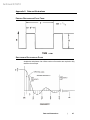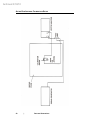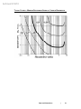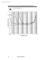
1
Archived 3/18/10
Model 3301B
Active Rod & Field
Antenna
User Manual
Archived 3/18/10
ETS-Lindgren L.P. reserves the right to make changes to any products herein to improve
functioning or design. Although the information in this document has been carefully reviewed and
is believed to be reliable, ETS-Lindgren does not assume any liability arising out of the
application or use of any product or circuit described herein; nor does it convey any license under
its patent rights nor the rights of others. All trademarks are the property of their respective
owners.
©Copyright 2000–2006 by ETS-Lindgren L.P. All Rights Reserved. No part of this
document may be copied by any means without written permission from
ETS-Lindgren L.P.
Trademarks used in this document: The ETS-Lindgren logo is a trademark of ETS-Lindgren L.P.
Revision Record | MANUAL 3301B, Part #399046, Rev. K
Revision
Description
Date
A–J
Initial Release, edits/updates
Through September, 2003
K
Edited rod capacitance, template/format
November, 2006
Internet Address
http://www.ETS-Lindgren.com
USA
1301 Arrow Point Drive
Cedar Park, TX 78613 USA
Tel: +1.512.531.6400
Fax: +1.512.531.6500
Email: [email protected]
Finland
Mekaanikontie 1, 27510
Eura, Finland
Tel: +358.2.838.330
Fax: +358.2.865.1233
Email: [email protected]
Japan
4-2-6, Kohinata
Bunkyo-ku, Tokyo 112-0006 Japan
Tel: +81.3.3813.7100
Fax: +81.3.3813.8068
Email: [email protected]
China
B507A Technology Fortune Center
No8 Xue Qing Road
Haidian District
Beijing Postcode: 100083 China
Tel: +86.010.827.30877
Fax: +86.010.827.55307
Email: [email protected]
ii
|
Archived 3/18/10
Table of Contents
Safety Symbol Definitions................................................................................................................. v
General Safety Considerations......................................................................................................... v
1.0 Introduction ................................................................................................................................ 7
2.0 Receiving Your Order ................................................................................................................ 9
2.1 Unpacking and Acceptance ................................................................................................... 9
2.2 Service Procedures................................................................................................................ 9
3.0 Maintenance ............................................................................................................................ 11
3.1 Maintenance Recommendations ......................................................................................... 11
3.2 Replacement and Optional Parts ......................................................................................... 11
4.0 Standard Configuration............................................................................................................ 13
4.1 Options ................................................................................................................................. 13
5.0 Specifications .......................................................................................................................... 15
5.1 Operational Specifications ................................................................................................... 15
5.1.1 Table of Acceptable Pulse Repetition Rates ................................................................. 16
5.2 Electrical Specifications ....................................................................................................... 16
5.3 Mechanical Specifications.................................................................................................... 17
6.0 Principles of Operation ............................................................................................................ 19
6.1 Description ........................................................................................................................... 19
6.2 Front Panel .......................................................................................................................... 19
6.3 Internal Options.................................................................................................................... 20
6.3.1 Factory Settings ............................................................................................................ 21
6.3.2 Proper Selection of Internal Attenuation ....................................................................... 22
7.0 Power Circuitry ........................................................................................................................ 23
7.1 Voltage-Selectable Battery Charger .................................................................................... 23
7.1.1 Operation....................................................................................................................... 23
7.1.2 Specifications ................................................................................................................ 24
7.2 Battery Low Indicator ........................................................................................................... 24
7.3 Fuses ................................................................................................................................... 24
8.0 Setup and Use ......................................................................................................................... 27
8.1 Setup .................................................................................................................................... 27
8.2 High Sensitivity Readings .................................................................................................... 28
|
iii
Archived 3/18/10
9.0 Theory of Operation ................................................................................................................. 29
9.1 The Rod ............................................................................................................................... 29
9.2 The Pre-Amplifier ................................................................................................................. 30
10.0 The Antenna Factor ............................................................................................................... 33
11.0 Antenna Impulse Response .................................................................................................. 35
11.1 Impulse Characteristics...................................................................................................... 35
11.2 Pulse Desensitization......................................................................................................... 36
11.3 Pulse Charging .................................................................................................................. 37
12.0 Calibration Procedure ............................................................................................................ 39
Appendix A: Warranty Policy for Standard EMCO Brand Products .............................................. 41
Scope and Duration of Warranties ............................................................................................. 41
Warranty Exclusions .................................................................................................................. 41
Buyer’s Remedies ...................................................................................................................... 42
Appendix B: European Community Declaration of Conformity ..................................................... 45
Appendix C: Data and Illustrations ................................................................................................ 47
Periodic Rectangular Pulse Train .............................................................................................. 47
Spectrum of Rectangular Pulse ................................................................................................. 47
Altering Pulse Width / Pulse Repetition Rate............................................................................. 48
Active Electric Field Antenna Calibration Fixture ....................................................................... 49
Active Rod Antenna Calibration Setup ...................................................................................... 50
Typical Curves—Minimum Discernible Signal at Various Bandwidths ...................................... 51
Typical Attenuation Effect for Switches 1 and 2 ........................................................................ 52
Typical Roll Off Curves for Switches 3 and 4 ............................................................................ 53
Typical Roll Off Curves—41” Rod Antenna, 0 dB Attenuation .................................................. 54
Typical Roll Off Curves—41” Rod Antenna, 10 dB Attenuation ................................................ 55
Typical Roll Off Curves—41” Rod Antenna, 30 dB Attenuation ................................................ 56
iv
|
Archived 3/18/10
Safety Symbol Definitions
This product and related documentation must be reviewed for familiarization with
safety markings and instructions prior to operation of the product.
Safety Symbol
!
OR
Definition
REFER TO MANUAL—When the product is marked with this symbol
refer to the instruction manual for additional information. If the
instruction manual has been misplaced, go to www.ets-lindgren.com for
downloadable files or contact ETS-Lindgren customer service.
CAUTION—Denotes a hazard. Failure to follow instructions could result
in minor personal injury and/or property damage. Text that follows the
symbol will provide proper procedures.
General Safety Considerations
Safety Symbol
WARRANTY
Definition
BEFORE SERVICING: CONTACT ETS-LINDGREN
(+1.512.531.6400)—Servicing or modifying the unit without
ETS-Lindgren authorization may void your warranty. If an attempt to
service the unit must be made, disconnect all electrical power prior to
beginning. Voltages exist at many points within the instrument that
could, if contacted, cause personal injury. Only trained service
personnel should perform adjustments and/or service procedures upon
this instrument. Capacitors inside this instrument may still be charged
even when the instrument is disconnected from the power source.
ONLY QUALIFIED PERSONNEL should operate or service this
equipment.
|
v
Archived 3/18/10
This page intentionally left blank.
vi
|
Archived 3/18/10
1.0 Introduction
The ETS-Lindgren Model 3301B is a broadband, high sensitivity electric-field
receiving antenna. The Model 3301B is composed of a monopole rod antenna
with a counterpoise, and a broadband, high impedance pre-amplifier. It is
designed to provide reception of an electric field in a signal band without tuning
or band switching from 30 Hz to 50 MHz. The 3 dB roll off points for the antenna
factor are at 170 Hz and 30 MHz. Between 250 Hz and 20 MHz, the antenna
factor is flat within +/- 1 dB. Despite the roll of the antenna factor, the usable
range is 30 Hz to 50 MHz.
The Model 3301B is designed for maximum sensitivity and dynamic range, and is
capable of sensing fields of 2 dBuV/m at 1 MHz with a 1 kHz bandwidth.
However, it will not saturate below a field strength of 0.7 V/m. As a result, the unit
boasts an extremely wide dynamic range of 115 dB nominal at mid-band. In
addition, at 10 and 30 dB (+/-10%), internal attenuators are provided. With the
attenuators the Model 3301B is usable in fields of up to 22 V/m. Therefore, the
dynamic range of the unit is expanded to 145 dB. A saturation indicator is
provided to alert the user to the need for using the internal attenuators
The Model 3301B is designed to provide the user with an extremely versatile
measurement tool. The flat antenna factor, extreme sensitivity, and ultra-wide
dynamic range make it a state of the art sensing instrument.
Introduction
|
7
Archived 3/18/10
This page intentionally left blank.
8
|
Introduction
Archived 3/18/10
2.0 Receiving Your Order
2.1 Unpacking and Acceptance
Step 1. Upon delivery of your order, inspect the shipping container(s) for
evidence of damage. Record any damage on the delivery receipt before signing
it. In case of concealed damage or loss, retain the packing materials for
inspection by the carrier.
Step 2. Remove the product from its shipping container(s). Save the container(s)
and any protective packing materials for future use.
Step 3. Check all materials against the packing list to verify that the equipment
you received matches what was ordered. If you find any discrepancies, note
them and call ETS-Lindgren Customer Service for further instructions.
Make sure you are satisfied with the contents and condition of your order prior to
placing the product into service.
2.2 Service Procedures
To return a system or system component for service:
Step 1. Contact ETS-Lindgren Customer Service to obtain an SRO, Service
Request Order.
Step 2. Briefly describe the problem in writing. Give details regarding the
observed symptom(s) or error codes, and whether the problem is constant or
intermittent in nature. Please include the date(s), the service representative you
spoke with, and the nature of the conversation. Include the serial number of the
item being returned.
Step 3. Package the system or component carefully. If possible, use the original
packing materials to return a system or system component to ETS-Lindgren at
the following address:
ETS-Lindgren
Attn: Service Department
301 Arrow Point Drive
Cedar Park, TX, USA 78613
Phone: +1.512.531.6400
Customer Service: +1.512.531.6498
Receiving Your Order
|
9
Archived 3/18/10
This page intentionally left blank.
10
|
Receiving Your Order
Archived 3/18/10
3.0 Maintenance
3.1 Maintenance Recommendations
To ensure reliable and repeatable long-term performance, annual recalibration of
your antenna by an ETS-Lindgren experienced technician is recommended. Our
staff can recalibrate almost any type or brand of antenna. Please call to receive a
Service Order Number prior to sending an antenna for calibration.
For more information about our calibration services, visit our website at
http://www.ETS-Lindgren.com.
3.2 Replacement and Optional Parts
Use the following tables to order replacement or optional parts for the
Model 3301B.
Replacement Part
Part Number
Collapsible Rod Element 41”
101263C
24” x 24” Counterpoise
100692
Rod Antenna Pre-Amplifier
100697B
Battery Charger
102615
Model 3301B Active Rod & Field
Antenna User Manual
399046
Table 1:
Replacement Parts List
Optional Part
Part Number
3301B Calibration Fixture
3301CB
Tripod, Linen Phenolic
3-TR
Remote Status Monitor
3301B-RM
25” Cable RG-223/U with BNC
Connectors
C-BNC
Replacement Batteries, 6V (2 required)
400009
Table 2:
Optional Parts List
Maintenance
|
11
Archived 3/18/10
This page intentionally left blank.
12
|
Maintenance
Archived 3/18/10
4.0 Standard Configuration
•
Adjustable monopole element
•
Antenna base with built-in preamplifier and an isolated female BNC connector
•
Counterpoise (60 cm)
•
Base drilled to accept EMCO or other tripod mounts with standard ¼” x 20 threads
•
Batteries and battery charger
•
Individually calibrated per ECSM or IEE Std. 291. Actual individual calibration
factors and signed Certificate of Calibration Conformance included with the
manual.
4.1 Options
REMOTE MONITOR
A 10-meter (32.8 ft) fiber optic Remote Monitor Option for remote display of
power-on and saturation indicators.
TRIPODS
ETS-Lindgren offers two nonmetallic, non-reflective tripods for use at both indoor
and outdoor EMC test sites.
•
Model 4-TR—Constructed of linen phenolic and delrin, designed with
an adjustable center post for precise height adjustments. Maximum
height for the 4-TR is 2.0 m (80.0 in), and minimum height is 94 cm
(37.0 in). This tripod can support up to an 11.8 kg (26.0 lb) load.
•
Model 7-TR—Allows several different configurations, including options
for manual or pneumatic polarization. The 7-TR provides increased
stability for physically large antennas. The unique design allows for
quick assembly, disassembly, and convenient storage. Quick height
adjustment and locking wheels provide ease of use during testing. This
tripod can support a 13.5 kg (30 lb) load. For the 7-TR series,
maximum height is 2.17 m (85.8 in), with a minimum height of .8 m
(31.8 in). The 7-TR is constructed of PVC and fiberglass components.
Standard Configuration
|
13
Archived 3/18/10
This page intentionally left blank.
14
|
Standard Configuration
Archived 3/18/10
5.0 Specifications
5.1 Operational Specifications
Frequency Range:
30 Hz to 50 MHz (maximum usable
bandwidth)
Low Frequency Roll Off:
The low frequency roll off is switch
selectable to be 3 dB down at 22 kHz,
1.9 kHz, or 170 Hz.
High Frequency Roll Off:
Antenna factor is 3 dB down at 30 MHz
Antenna Factor:
See data graphs included with manual. The
calibration graphs were taken in the low
gain setting. Unless otherwise noted, the
low frequency roll off is set at the 170 Hz
3 dB roll off point.
• 0.7 V/m narrowband without attenuation
and at the low gain setting
Saturation Level:
• 22 V/m with 30 dB of internal attenuation
selected
• 63 dBuV/m/MHz broadband saturation
level
Minimum Discernible Signal:
See data graphs included with manual. For
best sensitivity the unit should be in the low
gain setting with all internal attenuation off.
• 115 dB at mid-band (1 MHz)
Dynamic Range:
• 145 dB with the use of the internal
attenuators
Specifications
|
15
Archived 3/18/10
The saturation indicator will properly
indicate saturation for pulsed signals which
fall within the following boundaries:
Saturation Indicator Impulse Response:
1. The product of the pulse width to pulse
repetition rate must be greater than .003.
2. The pulse repetition rate must be less
than value listed for the applicable duty
cycle. See the following Table of
Acceptable Pulse Repetition Rates.
5.1.1 Table of Acceptable Pulse Repetition Rates
Duty Cycle
10
20
30
40
50
60
70
80
90
Maximum PRF
19.7 MHz
14.0 MHz
9.2 MHz
5.6 MHz
420.0 kHz
130.0 kHz
87.0 kHz
57.0 kHz
30.0 kHz
5.2 Electrical Specifications
Input Impedance:
The input impedance determines the low
frequency roll of point. Depending on the
low frequency roll off selected, the input
impedance is >20 megohms, 1 megohm or
100 kilohm.
Output Impedance:
50 ohm (nominal)
Saturation Impedance:
A red LED on the front panel will illuminate
when the unit begins to saturate or clip. The
saturation indicator will indicate accurately
for any gain and attenuator setting.
Battery Low Indicator:
The power light on the front panel also
serves as a battery low Indicator. If the
green light does not come on when the
power switch is engaged, then the battery
requires recharging. It is recommended that
the Model 3301B be connected to the
battery charger at all times when not in use.
16
|
Specifications
Archived 3/18/10
Batteries:
The Model 3301B is supplied with two 6V
sealed lead-acid batteries. The batteries will
operate for approximately 10 hours
between charges.
Battery Charger:
115/230 VAC 50/60 Hz switch selectable,
IEC input, two-stage battery charger with
fast and trickle charge modes.
• Type 3AG size .5 Amp, fast acting
Fuses:
• Or, 5 x 20 mm, .5 Amp, fast acting
• Internally mounted
5.3 Mechanical Specifications
Size:
7.38” x 4.62” x 3.5”
Weight:
Approximately 7 lbs
Tripod Mounting:
A ¼” x 20 hole is provided on the base for
tripod mounting. This is not intended as a
grounding point.
Counterpoise Mounting:
Four 6-32 holes are provided in the two
metal mounting bars on the top of the unit.
Antenna Element:
The antenna element may be set up to 41”.
Specifications
|
17
Archived 3/18/10
This page intentionally left blank.
18
|
Specifications
Archived 3/18/10
6.0 Principles of Operation
6.1 Description
The ETS-Lindgren Model 3301B electric field receiving antenna is composed of
three principal sections: a sensing rod, a ground plane or counterpoise, and a
broadband, high input impedance pre-amplifier.
The rod and counterpoise function together as an electrically short antenna over
ground plane. The pre-amplifier provides impedance transformation from the
extremely high impedance at the base of the rod to the 50 ohms required by
most receiving systems, and provides power gain to allow the sensing of very low
level signals.
6.2 Front Panel
On the front panel of the Model 3301B are the following:
•
Power switch
•
Gain switch
•
Saturation indicator
•
Battery Low/Power On indicator
•
BNC Output port
•
Battery Charging port
POWER SWITCH
The power switch is located on the lower right of the front panel. Activating the
power switch will turn on the Battery Low/Power On indicator (green).
BATTERY LOW/POWER ON INDICATOR
The Battery Low/Power On indicator is controlled by a voltage monitor circuit. If
the green indicator does not turn on, or if it turns off during use, the battery
requires charging.
GAIN SWITCH
In the middle left is the Gain switch, which increases the voltage output of the
gain stage in the amplifier by 10 dB. However, best sensitivity is achieved in the
low gain setting. The gain option provides additional output power for test
situations that require additional output.
Principles of Operation
|
19
Archived 3/18/10
SATURATION INDICATOR
The Saturation indicator is located above the power indicator. Readings should
not be taken when the unit indicates it is in saturation. If this occurs, input to the
unit should be reduced by placing the unit in the low gain mode or by switching in
internal attenuation. Impulsive type signals present a particular problem in that
they may put the unit into a non-linear region without triggering the saturation
circuit. When dealing with impulsive type signals, the 63 dBu V/m/MHz should be
strictly observed. If a signal exceeds this limit, the internal attenuation should be
applied. The limiting factor on handing impulsive signals is the unit output
capability. Therefore, once the internal attenuators are engaged, most higher
impulsive signals may be measured. For example, with the 30 dB attenuator
engaged, a 93 dBuV/m/MHz may be measured.
BATTERY CHARGING PORT
A Battery Charging port is provided for easy recharging of the sealed lead-acid
batteries internal to the unit. To charge the unit, turn off the power switch and
plug in the battery charger. The charging circuit will not charge the batteries
when the unit is on.
6.3 Internal Options
Internal to the unit is a 4-switch bank of slide switches. These switches control
the internal attenuation and the low frequency roll off.
To access the switch bank, hold the unit upside down and remove the bottom
cover. With the unit upside down and the front panel to the left:
20
|
•
The top switch, closest to the fuse holder, adds 10 dB of internal
attenuation.
•
The next switch down adds 30 dB of attenuation.
•
The third switch sets the low frequency roll off of 3 dB down at 1.9 kHz.
•
The fourth switch sets the low frequency roll off of 3 dB down at
22 kHz.
Principles of Operation
Archived 3/18/10
The antenna rod terminal is directly connected to the high
impedance gate of a field effect transistor. Do not lift the
antenna by the rod or touch it before properly grounding out
to the unit case. Accumulated static charge on test personnel
may damage the FET. If the antenna is used in a location
where static discharges are likely to be prevalent, attach a
grounding clip between the chassis and the antenna rod
while the antenna is being set up to prevent damage to the
amplifier circuitry.
The following diagram reflects the sequence of functions as they are connected
on the board.
30 dB Atten.
FUSE
10 dB Atten.
1.9 kHz LF Roll Off
22.0 kHz LF Roll Off
OFF
ON
FRONT PANEL
FUSE
10 dB (+/- 10%) Input Attenuator
30 dB (+/- 10%) Input Attenuator
1.9 kHz Low Frequency Roll Off
22.0 kHz Low Frequency Roll Off
Moving any switch to the extreme left, toward the center of the unit, activates the
indicated function. Moving the switch to the extreme right, toward the side of the
unit, deactivates that function. The most commonly used configuration will have
the 22 kHz roll off switch on and all other options off.
6.3.1 Factory Settings
The unit comes configured from the factory with the 22.0 kHz LF Roll Off set to
on. All other switches are off.
It is anticipated that the unit will normally be used with one of the roll off switches
on. Due to the abundance of low frequency ambient noise, in most settings using
the full bandwidth of the unit will make it very susceptible to saturation. However,
when extremely low frequency measurements are required, the unit is capable of
providing these measurements.
Principles of Operation
|
21
Archived 3/18/10
If both roll off switches are simultaneously set in the on position, the low
frequency 3 dB roll of point will be approximately 23 kHz.
6.3.2 Proper Selection of Internal Attenuation
When dealing with CW type signals, no attenuation is needed to measure field
strengths below 0.7 V/m. At approximately this level, the saturation indicator light
will come on. This indicates a need to switch on the 10 dB attenuator.
When the 10 dB attenuator is switched on, the Model 3301B can measure field
strengths up to 2.2 V/m without saturating. The unit retains 115 dB of dynamic
range, but the maximum reading before saturation is raised by 10 dB while the
minimum discernible signal is also raised by 10 dB. At 2.2 V/m, with the 10 dB
attenuator active, the saturation indicator light will again come on. This indicates
a need to switch the 30 dB attenuator on in place of the 10 dB attenuator.
The 30 dB internal attenuator will allow the unit to maintain calibration while
measuring field strengths up to 22 V/m. Again, the unit retains 115 dB of dynamic
range. Both the maximum reading before saturation and the minimum discernible
signal are raised 30 dB above their 0 dB attenuation values.
When using either of the attenuators, make sure to add the attenuation to the
antenna factor for accurate readings. Also, note that if both attenuator switches
are used, the resulting attenuation is approximately 31 dB and not 30 dB.
It is unwise to use attenuation to measure very low field strengths. When the field
strength falls below the minimum discernible signal, inaccurate field strength
measurements will result.
Both of the internal attenuators have a 10% tolerance, so they should be
calibrated before being used in critical applications.
A warning about the internal 30 dB attenuator: With the 30 dB attenuator
active, the unit resonates at 30 MHz. Therefore, the unit should not be used
above 15 MHz with the 30 dB attenuator active
The usefulness of the internal attenuators for impulse response testing is
discussed in Antenna Impulse Response on page 35.
22
|
Principles of Operation
Archived 3/18/10
7.0 Power Circuitry
The Model 3301B is powered by two 6 VDC sealed lead-acid batteries. A battery
charger is supplied with the unit. The battery charging port of the front of the unit
allows for easy recharging of the unit. Two internal fuses protect the unit from
unintentional shorting.
7.1 Voltage-Selectable Battery Charger
7.1.1 Operation
The EMCO brand Voltage-Selectable Battery Charger is solely intended for
charging the sealed lead-acid batteries found in EMCO products. The battery
charger is a means of providing the necessary charge voltage and current from
either a 115 or 230 VAC 50/60 Hz source.
It is necessary to select the proper input voltage prior to connecting the
battery charger to the power mains. The voltage select switch is located
adjacent to the power input receptacle.
To maintain safety requirements, use the CSA certified power cord provided. If it
is necessary to provide other means of attaching the battery charger to the power
mains it is required that a type HD 21 (PVC cord) or type HD22 (rubber cord) with
a nominal cross section of 0.75 mm be used.
The battery charger provides both fast and trickle charge operation. The charger
handles switching from one charge mode to the other automatically. The front
panel indicator marked Fast Charge lights when the battery charger is in the fast
charge mode. When the Power On light is illuminated and the Fast Charge light
is dark, the battery charger is in the trickle charge mode.
When not in use, the antenna should be connected to the battery charger in
trickle charge mode. Charging time is approximately eight hours when batteries
are completely discharged.
The antenna is not designed to operate using the battery charger as a
power source. Batteries should provide power to the amplifier for
approximately 16 hours before recharging is required.
Always remove main power before opening the housing.
Power Circuitry
|
23
Archived 3/18/10
The battery charger is protected against overcurrent by a 200 mA 250 VAC
time-delay fuse. If it becomes necessary to replace the fuse, use a fuse of the
same type and rating to maintain safe operations. The fuse is accessible by
removing the two Phillips head screws on the underside of the unit. The output of
the battery charger is protected against overcurrent conditions by use of
fold-back circuitry.
7.1.2 Specifications
Input voltage:
115/230 VAC selectable
Input frequency:
50/60 Hz
Input power:
20 VA max
Protection class:
Class II double insulated
Input fuse rating:
200 mA time-delay type 5 x 20 mm
Input power connection:
IEC-320 power inlet
Output voltage:
12 VDC (13.5-15 VDC)
Output current:
350 mA
Safety approvals:
TUV, CSA
7.2 Battery Low Indicator
If the Battery Low/Power On indicator on the front of the unit does not illuminate
when the power switch is on, the batteries should be recharged.
7.3 Fuses
Located inside the Model 3301B are two fuses, one for each battery. To replace
the fuses:
Disconnect the power cord and charger before opening the unit.
Replace the fuses with either Type AC size 0.5 AMP fast acting, or
5 x 20 mm fuses.
1. Use a Phillips head screwdriver to carefully remove the screws around
the edge of the bottom panel. Lift the bottom panel off the unit.
24
|
Power Circuitry
Archived 3/18/10
2. Locate the two fuses in their holders mounted on the circuit board, and
replace the fuses.
3. Replace the bottom panel of the unit and reinstall the screws.
Power Circuitry
|
25
Archived 3/18/10
This page intentionally left blank.
26
|
Power Circuitry
Archived 3/18/10
8.0 Setup and Use
The Model 3301B is designed for ease of use, and is designed for five accurate
reading types in a variety of test environments. However, precision
measurements require an understanding of the test parameters that will
adversely affect test results. No single test instrument can insure accurate
results. For best results, the user should become thoroughly familiar with both
the practical and theoretical operating parameters for this unit.
8.1 Setup
Before beginning the setup procedure, make sure that the technician is
completely grounded using an ESD wrist strap at an ESD protective workstation
for protection of the antenna FET. Make sure antenna power is off.
The Model 3301B is quite sensitive to test setup and proper use. Two grounding
strips are provided on top of the unit. These are intended to attach to a
counterpoise, which is provided with the unit
To assemble the unit, first touch the two metal counterpoise mounting strips
located on top of the antenna chassis, then remove the two screws from each
strip. The unit is meant to be under the counterpoise. In this way the body of the
unit does not intrude into the field being measured. Open the counterpoise and
attach it to the mounting strips using the screws that were just removed. Next,
the rod should be attached to the fitting at the center of the unit, through the hole
in the counterpoise. The rod should then be extended to 41”. The output of the
unit should be connected to a 50-ohm receiver, spectrum analyzer, or RF
voltmeter. The technician should remove the ESD wrist strap at this time.
The unit is activated by pressing in the power switch on the front panel. The
switch will turn to green and the battery low/power indicator light will come on.
Should the indicator light not come on, the level of the battery charge should be
checked. Finally, the state of the gain switch should be checked. It is anticipated
that in most applications the low gain setting will be used.
The unit housing hangs under the counterpoise with the antenna rod passing
through an opening in the counterpoise.
It should be noted that the brass tripod mounting bracket on the bottom of the
unit is not a ground location. The unit must be attached to a counterpoise through
the top grounding strips. In screen room testing, the counterpoise should be
solidly attached to the screen room wall, as required for military testing.
If the unit is to be mounted on a tripod, it is recommended that the tripod be
non-conductive.
Setup and Use
|
27
Archived 3/18/10
8.2 High Sensitivity Readings
The Model 3301B is optimized to facilitate extremely sensitive readings. For best
performance, all internal attenuation should be off. The gain switch should be
placed in the low gain setting. The noise limiting factor on the Model 3301B is the
high front end impedance presented to the FET. So when the gain stage output
is increased with the gain switch, the noise is also amplified and actually
increased slightly due to additional noise added in the gain state. The high gain
setting is primarily intended to provide additional signal strength for receivers that
require it
A set of minimum discernible signal graphs is included in this manual. These
graphs represent the smallest signal which can be detected with the
Model 3301B. The data plotted are the noise output of the unit. As a result, this
forms the noise measurement for a signal plus noise-to-noise ratio of 3 dB.
Several typical bandwidths are presented. To calculate the expected sensitivity at
some other bandwidth, a 10*log relation should be used.
EXAMPLE
Determine the sensitivity with a 3 kHz bandwidth at 1 MHz. The minimum
discernible signal (MDS) at 1 MHz with a 1 kHz bandwidth is read from the graph
at –2 dBuV/m. The ratio of the bandwidth is 3/1=3. Taking 10*log(3), we get
4.77 dB. Therefore, the expected sensitivity would be –
2dBuV/m+4.77dB=2.77dBuV/m.
28
|
Setup and Use
Archived 3/18/10
9.0 Theory of Operation
9.1 The Rod
There are three factors of primary interest in understanding a rod antenna. These
factors are its effective electrical length, the impedance it presents to the
measurement system, and the interaction of the rod with the ground. The
discussion here will contain itself to discussing an electrically short antenna
element. The Model 3301B is designed to be electrically short over its
measurement range. Electrically short means an antenna that is designed to
have the physical antenna element be short when compared to the wavelength of
the highest frequency in its measurement range. The current distribution on any
rod antenna will be sinusoidal. If a rod is short enough with respect to the
wavelength being measured, that distribution will approach a linear distribution
and may be assumed to be linear for all practical purposes. The linear current
distribution will allow for linear scaling of the rod length. If the rod length is
reduced by half, then the received voltage will be reduced by half. The 41” rod is
approximately a meter long. Electrically, then, it is a half-meter long. The
assumption of linearity will remain accurate at least to one-eighth wavelength.
At this point some resonance behavior is possible. A rod that is electrically a
half-meter is one-eighth wavelength at 75 MHz. To keep the response of the unit
linear and avoid resonance behavior, the Model 3301B pre-amplifier is limited to
roll off before this frequency has been reached. However, this avoidance of
possible resonance carries the penalty of 6 dB on the antenna factor. Because
field strength is measured as volts per meter, the measurement must be
normalized to 1 meter. This means that 6 dB must be added to a reading taken
with a half-meter rod.
The second factor of concern is the impedance the rod presents to the
measurement system. The resistive component is non-significant in this situation.
The controlling impedance is the capacitance of the rod to ground. This
capacitance may be calculated by the formula:
C = [55.63 * h] / [ln (h/a)]
h = length of the rod, in meters
a = radius of the rod, in meters
The natural logarithm of h over a is represented by ln. For the Model 3301B rod,
the capacitance is 10 picofarads (pF). This capacitance is significant because it
combines with the total input capacitance of the amplifier to form a voltage
divider. It can quickly be seen that if the FET input capacitance and circuit stray
total 10 pF, there will be a 6 dB loss through this stray capacitance. Even if the
total input capacitance where reduced to 4 pF there would be a 2.5 dB loss.
Theory of Operation
|
29
Archived 3/18/10
Finally, the interaction of the rod with the ground must be understood. The
theoretical understanding of the rod assumes that it operates in reference to an
infinite ground at 0 Volt potential. The closer the test situation is to this scenario
the more accurate will be the readings. A small vestigial ground is provided with
the unit in the form of a counterpoise. Care should be taken to reference this
counterpoise to true ground.
The procedures for this are carefully explained in various standards. If the
counterpoise is not well grounded, an impedance may build up through the
cabling and other instrumentation. Reading differences of as much as 20 dB can
be found with ungrounded counterpoises. This will be true for all rod antennas
regardless of their design.
Another counterpoise problem is the potential for positive feedback. Good
amplifier design calls for the output to be 180 degrees out of phase with the
output signal so that the shield current is in phase with the input. If the shield and
counterpoise are tied through the body of the unit, then the counterpoise will
receive some of this current. If the counterpoise does not have an extremely low
impedance to ground, then this return current can drive a potential on the
counterpoise in phase with the input resulting in errant readings. The
Model 3301B has an internal common mode choke to minimize the impact of an
inadequate test setup. However, proper test configuration will always be critical
to ensure measurement accuracy.
Also of concern is the contribution of edge effects from the vestigial ground
plane. Most theory is developed on the assumption of one infinite ground plane.
How using a small vestigial ground plane or counterpoise affects the theory has
not been well studied to date. Even more complicated is the effect of this vestigial
ground plane when the unit is used in a screen room with the ground planes on
all sides. In practice, the best results are obtained by tightly typing the
counterpoise to the screen room through an ultra low impedance ground strap.
This at least assures that at the lower frequencies all of these surfaces are at an
equal potential.
9.2 The Pre-Amplifier
The Model 3301B pre-amplifier is designed in two stages. The first stage
provides impedance transformation and current gain. The second stage provides
voltage gain and impedance mating on a 50-ohm output.
The first stage of the pre-amplifier contains an n-channel JFET and an NPN
bipolar silicon transistor. Through the use of extremely precise layout techniques,
careful parts selection and feedback to virtually eliminate the Miller effect, the
total input capacitance is kept extremely low. This low capacitance in turn allows
for an extremely high input impedance.
30
|
Theory of Operation
Archived 3/18/10
It is the output impedance which determines the effective low frequency cutoff of
the unit. The Model 3301B is still usable at an extremely low 30 Hz. In fact,
artificial limiting was introduced to protect the unit in situations where overloading
from power frequencies would be a problem. The low frequency roll off switches
in to unit allow the user to set the low frequency cutoff according to the particular
testing needs.
The second stage is made up of three exceptionally high quality transistors. The
first is configured common emitter for voltage gain and to give a precise
180 degrees phase reversal for the output. The second two transistors for a
Darlington pair to drive the 50-ohm output. The output of this stage is then DC
isolated, matched to 50 ohm and passed through a common mode choke. The
result is that cable VSWR and common mode noise problems are minimized.
The dynamic limits of the Model 3301B are set by the amplifier. Sensitivity is
determined by the noise developed in the first stage. The ultimate limit on
sensitivity is determined by the thermal noise generated by the input impedance.
The impedance presented to the amplifier by the rod is almost entirely capacitive.
A 41” rod typically presents an impedance of about 12 pF. Therefore, the input
impedance presented to the amplifier will decline with increasing frequency. At
the low frequencies, where the input impedance is high, the thermal noise
generated by this impedance will also be high. If the input impedance of the
amplifier is lowered to reduce thermal noise then the rod will be loaded down and
lose sensitivity. This combination of thermal noise and rod impedance sets an
ultimate limit on the sensitivity achievable by active rod antennas. The sensitivity
of the Model 3301B improves with frequency in direct relation to the declining
input impedance.
A common mistake made in regard to sensitivity is to ask what the noise figure of
an active rod is. Noise figure is defined as: The ratio of output noise of a unit over
the output noise expected solely due to the thermal noise of the resistance of the
input impedance. Since the input in the case of a rod is primarily reactive, the
definition literally has no meaning. What is useful is to determine what the
minimum discernible signal of a unit is. That is, what is the smallest signal which
can be seen in the presence of the amplifier noise? There is a trick here. The
smallest signal seen above the noise in a rod antenna is not determined by the
noise of the amplifier. Signal is drained away through capacitive loss before it
reaches the amplifier. An amplifier with more noise may actually be more
sensitive if it also loses less signal to capacitance at the input.
The upper limit of the Model 3301B is determined by the ability of the gain stage
to amplify a signal. The gain stages capable of handing field strengths of 0.7 V/M
are available. Impulsive type signals produce the same effect but in such a way
as may not be immediately obvious. An impulse signal presents the amplifier with
signals at a number of frequencies all in phase with each other so that
measurement of the field strength at any one frequency will not appear to be very
Theory of Operation
|
31
Archived 3/18/10
high. However, the amplifier is being called upon to amplify signals at many
frequencies simultaneously. In the time domain, the amplifier would be seen to
be presented with quite a large power demand. The result is that impulsive
signals appear to saturate the amplifier at must lower signal levels. The
Model 3301B has been measured to begin going non-linear at 64 dBuV/m/MHz.
A saturation indicator is provided on the unit. This indicator will eliminate many
false readings due to non-linear operation. The saturation indicator has been
carefully tested to give an accurate, early warning of possible saturation.
However, some types of impulse signals may not trigger the indicator. The user
must, therefore, be careful to observe the published limits. Should these be
exceeded, the internal attenuation provided would relieve the problem.
32
|
Theory of Operation
Archived 3/18/10
10.0 The Antenna Factor
The antenna factor data provided with the unit is simply a ratio of the field
strength presented to the unit to the voltage output from the unit at that field
strength. By adding the antenna factor to a given output, the field strength may
be derived. The antenna factor in the Model 3301B combines several factors.
The first factor is the 6 dB required to normalize the rod to 1 meter. The next is
the measured capacitive loss at the front of the unit of about 4 dB. Then there is
the gain of the amplifier itself, 15 dB. Finally, 6 dB is required to conjugate match
the output to 50 ohm. The antenna factor is the sum of these factors. A typical
result might be:
– 6 dB Rod Normalization
– 4 dB Capacitive Loss
+ 15 dB Preamlifier Gain
– 6 dB 50 ohm Matching Loss
= – 1 dB Gain Over Field Strength or Antenna Factor of 1 dB
The Antenna Factor
|
33
Archived 3/18/10
This page intentionally left blank.
34
|
The Antenna Factor
Archived 3/18/10
11.0 Antenna Impulse Response
The Model 3301B is designed and optimized for the measurement of CW type
signals. However, this unit is fully capable of dealing accurately with impulsive
type signals, with some special considerations. This section guides the user who
intends to use the Model 3301B to measure impulsive signals. By following the
provided guidance, accurate measurements of impulsive signals may be
performed. The Model 3301B may be used to measure the important
characteristics of an impulse signal that fall within its bandwidth and dynamic
range. However, the measurement of impulsive signals requires some special
cautions to avoid saturation of the antenna amplifier.
11.1 Impulse Characteristics
Before discussing the Model 3301B response to impulse signals, a brief review of
the nature of impulse signals is appropriate. For our purposes we will consider a
specific type of impulse signal, the periodic, rectangular pulse. The pulse may be
described by three parameters: the pulse width, t; the pulse repetition rate, PRF;
and the pulse amplitude, A. For a diagram, see Periodic Rectangular Pulse Train
on page 47. By Fourier analysis, we may convert this time domain representation
into its frequency domain equivalent. In the frequency domain, the impulse
becomes an infinite series of discrete spectral lines whose envelope is described
by the formula:
Y=K*sin(x)/X
K = A*t*PRF
The nulls occur at regular intervals spaced n/t apart, where n is an integer. The
discrete spectral lines are spaced evenly, at internal multiples of the PRF. For an
illustration, see Spectrum of Rectangular Pulse on page 47. Two characteristics
should be noted. First, increasing the pulse width, t, narrows the separation of
the nulls. So wider pulses tend to concentrate their energy in a narrower
frequency span. Second, decreasing the PRF decreases the frequency
separation of the individual spectral lines. For an illustration, see Altering Pulse
Width/Pulse Repetition Rate on page 48.
By considering the frequency domain representation, any antenna response to
an impulse may be understood. The antenna will only pass those spectral
components that fall within its bandwidth. In the case of the Model 3301B,
components above 30 MHz will be attenuated or not passed at all. Remember, to
fully describe a rectangular pulse, an infinite bandwidth is required. The lack of
high frequency components shows up on the time domain as a rounding of sharp
corners and a slowing of the rise and fall.
Antenna Impulse Response
|
35
Archived 3/18/10
In the same way, the antenna will not efficiently pass spectral components that
fall below its bandwidth. For the Model 3301B, the selected low frequency roll off
will determine how wideband the response is. The very low frequency
components basically describe the flat top and bottom of the time domain pulse.
So, when the waveform is band limited by the antenna, the resulting waveform
will have a decay constant returning the output to ground rather than maintaining
a flat topped pulse.
A third phenomenon that occurs when measuring impulse type waveforms is that
saturation of the amplifier is harder to detect. By definition, impulsive type signals
spread their energy over many spectral components. So, when viewed in the
frequency domain, the energy demanded of the antenna amplifier may appear
much lower than it actually is. The energy demanded of the antenna amplifier to
properly pass a pulse is not just the peak pulse in the frequency domain
waveform, but rather the sum of the energy contained in all the spectral lines. By
looking in the time domain, it is easy to see that the amplifier must provide the
energy to go from ground to the pulse peak almost instantaneously. The impulse
delivers all its frequency domain spectral components in phase. So the antenna
must provide the vector sum of all the frequency domain spectral lines.
Therefore, extra care must be taken to protect the antenna amplifier from
saturation when making impulse measurements in the frequency domain. The
internal attenuators in the Model 3301B allow it to overcome many of the barriers
which earlier units presented to such measurements. These attenuators allow the
user to safely keep the amplifier in its linear region.
The saturation indicator in the Model 3301B will provide an accurate warning of
impending saturation, provided two conditions are met. First, the product of the
pulse width to pulse repetition rate must be greater than 0.003. Second, the
pulse repetition rate must be less than the value listed in Table of Acceptable
Pulse Repetition Rates on page 16.
If an impulse falls outside of these two parameters, the saturation indicator will
not accurately warn of saturation. However, the antenna will accurately handle
the impulse signal within its bandwidth and dynamic range limitations.
The reasons for these requirements are two engineering trade-offs which must
be made, and are explained in the next two sections.
11.2 Pulse Desensitization
The Model 3301B saturation indicator operates by creating a DC level on a
capacitor feed through a rectifying diode. This DC level is then compared to a
second DC level which is set at the amplifier 1 dB compression point. This circuit
works extremely well for CQ type signals. However, for fast transients the
capacitor, like all capacitors, has an integrating effect. The DC level established
by a fast transient is spread out in time. After the pulse passes, the capacitor
36
|
Antenna Impulse Response
Archived 3/18/10
begins to discharge through its resistance to ground. If the PRF is slow enough
so that the capacitor is fully discharged before the next pulse arrives, it may
never trigger the indicator. The antenna amplifier, on the other hand, must satisfy
the instantaneous energy demand. It must respond to the peak demand without
any integrating effect. If the product of the pulse width and PRF is less than
0.003, the saturation indicator will fail to indicate properly. The time constant of
the saturation indicating capacitor also sets the persistence of the saturation
circuit. To have the saturation circuit cease to indicate saturation within a
reasonable time after the antenna moves out of saturation, a reasonable RC time
constant must be maintained. This choice of RC time constant also creates this
limit for impulsive signals. In this region, the user must closely monitor the
antenna output for saturation.
11.3 Pulse Charging
The second criterion that must be met is that the PRF must fall below the rate
listed in Impulse Characteristics on page 35 for the appropriate duty cycle. This
requirement is created by the AC coupling in the Model 3301B circuitry. To allow
maximum dynamic range through the Model 3301B, the various stages are AC
coupled. Furthermore, to allow the extremely broad bandwidth of the unit, large
value, low impedance capacitors are used to provide the AC coupling. When a
pulse passes through these capacitors, a charge is developed. After the pulse
passes, this charge drains through the associated resistance to ground at an
established RC constant. However, if the next pulse occurs before the residual
charge has fully discharged, then a residual DC bias is created.
This bias artificially alters the DC level on the saturation indicator comparison
capacitor, causing it to fail to properly indicate saturation. Again, in this region,
the user must closely monitor the antenna output for saturation.
Antenna Impulse Response
|
37
Archived 3/18/10
This page intentionally left blank.
38
|
Antenna Impulse Response
Archived 3/18/10
12.0 Calibration Procedure
ETS-Lindgren recommends the equivalent capacitance method of calibration for
the Model 3301B active rod antenna. To check the calibration, a Model 3301B
calibration test fixture is required. This fixture contains a resistive T and a
capacitor. The T allows for accurate reading of the input to the fixture. The
capacitor feeds the amplifier through the same impedance as the 41” rod
presents to it. The result is a simple, yet extremely accurate calibration.
Periodic checks of performance are recommended. To calibrate the unit, simply
attach the calibration fixture and ground it to the Model 3301B housing through
one of the counterpoise mounting holes. Place a signal source on one leg of the
fixture and a receiver on the other leg. Then terminate the output of the unit with
50 ohms. Read the input signal strength. The input signal strength measured
through the calibration fixture must have 11 dB added to it. The 11 dB is
composed of 6 dB required to normalize the rod to 1 meter and 5 dB of signal
loss through the resistive divider in the T. After the input is read, move the
receiver cable to the output of the unit and place a 50-ohm load on the now open
leg of the calibration fixture. Read the unit output. The antenna factor is the input
plus 11 dB minus the output, both readings assumed to be logarithmic.
ETS-Lindgren recommends the following input voltage levels for field calibration:
Voltage
250 mV
450 mV
8V
Internal Attenuation
0 dB
10 dB
30 dB
EXAMPLE
Suppose a reading is taken with a 1 MHz signal input to the calibration fixture.
The input is read as 50 dBuV and the output is read as 59 dBuV. The antenna
factor is then the input plus 11 dB minus the output of
50 dBuV + 11 dB - 59 dBuV = 2dB.
Calibration Procedure
|
39
Archived 3/18/10
This page intentionally left blank.
40
|
Calibration Procedure
Archived 3/18/10
Appendix A: Warranty Policy for Standard EMCO Brand Products
SCOPE AND DURATION OF WARRANTIES
Seller warrants to Buyer that the Standard EMCO Brand Products Excluding 5211 &
5220 be (1) free from defects in material, manufacturing workmanship, and title, and (2)
conform to the Seller’s applicable product descriptions and specifications, if any,
contained in or attached to Seller’s quotation. If no product descriptions or specifications
are contained in or attached to the quotation, Seller’s applicable product descriptions and
specifications in effect on the date of shipment shall apply. The criteria for all testing shall
be Seller’s applicable product specifications utilizing factory-specified calibration and test
procedures and instruments.
All product warranties, except the warranty of title, and all remedies for warranty failures
are limited in time as shown in the following table.
Product Warranted
Duration of Warranty Period
Standard EMCO Brand Products
Excluding 5211 & 5220
2 Years
Any product or part furnished to Buyer during the warranty period to correct a warranty
failure shall be warranted to the extent of the unexpired term of the warranty applicable to
the repaired or replaced product.
The warranty period shall commence on the date the product is delivered to Buyer;
however, if Seller assembles the product, or provides technical direction of such
assembly, the warranty period for such product shall commence on the date the
assembly of the product is complete. Notwithstanding the foregoing, in the event that the
assembly is delayed for a total of thirty (30) days or more from the date of delivery for any
reason or reasons for which Seller is not responsible, the warranty period for such
product may, at Seller’s options, commence on the thirtieth (30th) day from the date such
product is delivered to Buyer. Buyer shall promptly inspect all products upon delivery. No
claims for shortages will be allowed unless shortages are reported to Seller in writing
within ten (10) days after delivery. No other claims against Seller will be allowed unless
asserted in writing within thirty (30) days after delivery (or assembly if the products are to
be assembled by Seller) or, in the case of alleged breach of warranty, within the
applicable warranty period.
WARRANTY EXCLUSIONS
Except as set forth in any applicable patent indemnity, the foregoing warranties are
exclusive and in lieu of all other warranties, whether written, oral, express, implied, or
statutory. EXCEPT AS EXPRESSLY STATED ABOVE, SELLER MAKES NO
WARRANTY, EXPRESS OR IMPLIED, BY STATUTE OR OTHERWISE, WHETHER OF
MERCHANTABILITY OR FITNESS FOR ANY PARTICULAR PURPOSE OR USE OR
OTHERWISE ON THE PRODUCTS, OR ON ANY PARTS OR LABOR FURNISHED
DURING THE SALE, DELIVERY OR SERVICING OF THE PRODUCTS THERE ARE
NO WARRANTIES WHICH EXTEND BEYOND THE DESCRIPTION ON THE FACE
HEREOF.
Warranty Policy for Standard EMCO Brand Products
|
41
Archived 3/18/10
Warranty coverage does not include any defect or performance deficiency (including
failure to conform to product descriptions or specifications) which results, in whole or in
part, from (1) negligent storage or handling of the product by Buyer, its employees,
agents, or contractors, (2) failure of Buyer to prepare the site or provide an operating
environmental condition in compliance with any applicable instructions or
recommendations of Seller, (3) absence of any product, component, or accessory
recommended by Seller but omitted at Buyer’s direction, (4) any design, specification, or
instruction furnished by Buyer, its employees, agents or contractors, (5) any alteration of
the product by persons other than Seller, (6) combining Seller’s product with any product
furnished by others, (7) combining incompatible products of Seller, (8) interference with
the radio frequency fields due to conditions or causes outside the product as furnished by
Seller, (9) improper or extraordinary use of the product, or failure to comply with any
applicable instructions or recommendations of Seller, or (10) acts of God, acts of civil or
military authority, fires, floods, strikes or other labor disturbances, war, riot, or any other
causes beyond the reasonable control of Seller. This warranty does not cover (1) contact
fingers or replacements unless loss is caused by a defect in material or manufacturing
workmanship within the scope of this warranty (2) items designed to be consumable and
(3) removal and reconstruction of walls, partitions, ceilings and other facility costs arising
from repair or replacement of the product or parts thereof by Seller under the warranty.
Seller does not warranty products of others which are not included in Seller’s published
price lists for shielding products and systems supplies and accessories.
BUYER’S REMEDIES
If Seller determines that any product fails to meet any warranty during the applicable
warranty period, Seller shall correct any such failure by either, at its option, repairing,
adjusting, or replacing without charge to Buyer any defective or nonconforming product,
or part or parts of the product. Seller shall have the option to furnish either new or
exchange replacement parts or assemblies.
Warranty service during the applicable warranty period will be performed without charge
to Buyer within the contiguous 48 United States during Seller’s normal business hours.
After the warranty period, service will be performed at Seller’s prevailing service rates.
Subject to the availability of personnel, after-hours service is available upon request at an
additional charge. For service outside the contiguous 48 United States, travel and per
diem expenses, when required, shall be the responsibility of the Buyer, or End User,
whichever is applicable.
The remedies set forth herein are conditioned upon Buyer promptly notifying Seller within
the applicable warranty period of any defect or nonconformance and making the product
available for correction
The preceding paragraphs set forth Buyer’s exclusive remedies and Seller’s sole liability
for claims based on failure of the products to meet any warranty, whether the claim is in
contract, warranty, tort (including negligence and strict liability) or otherwise, and however
instituted, and, upon the expiration of the applicable warranty period, all such liability shall
terminate. IN NO EVENT SHALL SELLER BE LIABLE TO BUYER FOR ANY SPECIAL
INDIRECT, INCIDENTAL OR CONSEQUENTIAL DAMAGES OF ANY KIND ARISING
OUT OF, OR AS A RESULT OF, THE SALE, DELIVERY, NON-DELIVERY, SERVICING,
ASSEMBLING, USE OR LOSS OF USE OF THE PRODUCTS OR ANY PART
THEREOF, OR FOR ANY CHARGES OR EXPENSES OF ANY NATURE INCURRED
WITHOUT SELLER’S WRITTEN CONSENT DESPITE ANY NEGLIGENCE ON BEHALF
OF THE SELLERIN NO EVENT SHALL SELLER’S LIABILITIES UNDER ANY CLAIM
42
|
Warranty Policy for Standard EMCO Brand Products
Archived 3/18/10
MADE BY BUYER EXCEED THE PURCHASE PRICE OF THE PRODUCT IN RESPECT
OF WHICH DAMAGES ARE CLAIMED This agreement shall be construed in accordance
with laws of the State of Illinois In the event that any provision hereof shall violate any
applicable statute, ordinance, or rule of law, such provision shall be ineffective to the
extent of such violation without invalidating any other provision hereof.
Any controversy or claim arising out of or relating to the sale, delivery, nondelivery,
servicing, assembling, use or loss of use of the products or any part thereof or for any
charges or expenses in connection therewith shall be settled in Austin, Texas by
arbitration in accordance with the Rules of the American Arbitration Association, and
judgment upon the award rendered by the Arbitrator may be entered in either the Federal
District Court for the Western District of Texas or the State District Court in Austin, Texas,
all of the parties hereto consenting to personal jurisdiction of the venue of such court and
hereby waive the right to demand a jury trial under any of these actions.
Warranty Policy for Standard EMCO Brand Products
|
43
Archived 3/18/10
This page intentionally left blank.
44
|
Warranty Policy for Standard EMCO Brand Products
Archived 3/18/10
Appendix B: European Community Declaration of Conformity
The EC Declaration of Conformity is the method by which EMC Test Systems, L.P.
declares that the equipment listed on this document complies with the EMC and Lowvoltage Directives.
Factory
Issued by
EMC Test Systems, L.P.
EMC Test Systems, L.P.
P.O. Box 80589
P.O. Box 80589
Austin, Texas USA 78708-0589
Austin, Texas USA 78708-0589
The products manufactured under the EMCO product name and listed below are eligible to
bear the EC Mark:
– Model 3301B Active Rod Antenna
– Part number 102615 Battery Charger
APPLICABLE REQUIREMENTS
Standard
Criteria
EN61010-1
Safety requirements for electrical equipment for measurement, control
and laboratory use
EN60742/1989
Isolating transformers and safety isolating transformers
EN55022
Class B
IEC 801-2
Level 2 4/8kV
IEC 801-3
Level 2 3V/m
IEC 801-4
Level 2 .5 I/O, 1kV AC
AUTHORIZED SIGNATORIES
Bruce Butler, General Manager
James C. Psencik, Engineering Mgr
Charles Garrison, Quality Assurance
Date of Declaration: December 10, 1996
The authorizing signature on the EC Declaration of Conformity document authorizes
EMC Test Systems, L.P. to affix the CE mark to the indicated product. CE marks placed on
these products will be distinct and visible. Other marks or inscriptions liable to be confused
with the CE mark will not be affixed to these products. EMC Test Systems, L.P. has
ensured that appropriate documentation shall remain available on premises for inspection
and validation purposes for a period of no less than 10 years.
European Community Declaration of Conformity
|
45
Archived 3/18/10
This page intentionally left blank.
46
|
European Community Declaration of Conformity
Archived 3/18/10
Appendix C: Data and Illustrations
PERIODIC RECTANGULAR PULSE TRAIN
SPECTRUM OF RECTANGULAR PULSE
Amplitudes and phases of an infinite number of harmonics are required to fully
describe the envelope.
Data and Illustrations
|
47
Archived 3/18/10
ALTERING PULSE WIDTH / PULSE REPETITION RATE
The following figures A–D depict the effect of altering either the pulse width or
pulse repetition rate. A narrow pulse width (A, C) spreads the pulse energy over
a wider frequency band. Wider pulses (B, D) cause narrower lobes. A low pulse
repetition rate (A, B) creates widely spaced spectral lines. Faster rates (C, D)
increase the spectral line density.
48
|
Data and Illustrations
Archived 3/18/10
ACTIVE ELECTRIC FIELD ANTENNA CALIBRATION FIXTURE
Data and Illustrations
|
49
Archived 3/18/10
ACTIVE ROD ANTENNA CALIBRATION SETUP
50
|
Data and Illustrations
Archived 3/18/10
TYPICAL CURVES—MINIMUM DISCERNIBLE SIGNAL AT VARIOUS BANDWIDTHS
Data and Illustrations
|
51
Archived 3/18/10
TYPICAL ATTENUATION EFFECT FOR SWITCHES 1 AND 2
52
|
Data and Illustrations
Archived 3/18/10
TYPICAL ROLL OFF CURVES FOR SWITCHES 3 AND 4
Data and Illustrations
|
53
Archived 3/18/10
TYPICAL ROLL OFF CURVES—41” ROD ANTENNA, 0 DB ATTENUATION
Generator output 250 mV
54
|
Data and Illustrations
Archived 3/18/10
TYPICAL ROLL OFF CURVES—41” ROD ANTENNA, 10 DB ATTENUATION
Generator output 250 mV
Data and Illustrations
|
55
Archived 3/18/10
TYPICAL ROLL OFF CURVES—41” ROD ANTENNA, 30 DB ATTENUATION
Generator output 8000 mV
56
|
Data and Illustrations