1
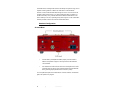
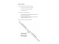
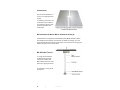
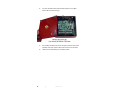
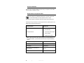
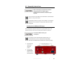
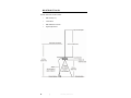
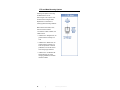
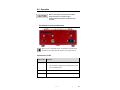
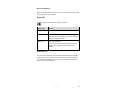
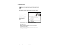
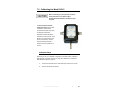
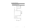
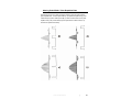
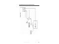
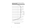
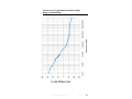
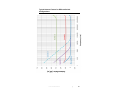
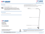
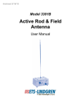
Model 3301C
Active Monopole Antenna
User Manual
Model 3301C Antenna Base
ETS-Lindgren L.P. reserves the right to make changes to any product described
herein in order to improve function, design, or for any other reason. Nothing
contained herein shall constitute ETS-Lindgren L.P. assuming any liability
whatsoever arising out of the application or use of any product or circuit
described herein. ETS-Lindgren L.P. does not convey any license under its
patent rights or the rights of others.
© Copyright 2009–2011 by ETS-Lindgren L.P. All Rights Reserved. No part
of this document may be copied by any means without written permission
from ETS-Lindgren L.P.
Trademarks used in this document: The ETS-Lindgren logo is a trademark of
ETS-Lindgren L.P.
Revision Record
MANUAL,3301C ACTIVE ROD ANTENNA,USER | Part #399792, Rev. C
Revision
Description
Date
A
Initial Release
October, 2009
B
Updated part numbers in
December, 2009
Replacement and
Optional Parts
C
Updated monopole rod
element information
ii
|
July, 2011
Table of Contents
Notes, Cautions, and Warnings ................................................ v
General Notices.......................................................................... v
1.0 Introduction .......................................................................... 7
Standard Configuration .................................................................................. 8
Antenna Base ........................................................................................ 8
Monopole Element ................................................................................. 9
Counterpoise ....................................................................................... 10
Rechargeable AA Nickel-Metal Hydride batteries (8) .......................... 10
MIL-STD-461F Test Kit ........................................................................ 10
4-TR Light Tripod (Optional) ........................................................................ 11
ETS-Lindgren Product Information Bulletin ................................................. 12
2.0 Maintenance ....................................................................... 13
Battery Replacement ................................................................................... 13
Annual Calibration ....................................................................................... 16
Replacement and Optional Parts ................................................................. 16
Service Procedures ..................................................................................... 17
3.0 Specifications..................................................................... 19
Operational Specifications ........................................................................... 19
Table of Acceptable Pulse Repetition Rates ....................................... 20
Electrical Specifications ............................................................................... 21
Physical Specifications ................................................................................ 21
AC Adapter & Battery Specifications ........................................................... 22
4.0 Assembly Instructions ...................................................... 23
Counterpoise and Monopole Element ......................................................... 23
MIL-STD-461F Test Kit ................................................................................ 28
5.0 Mounting Instructions ....................................................... 31
4-TR Light Tripod Mounting Options ............................................................ 31
7-TR and Mast Mounting Options ................................................................ 32
2x2 Boom Mounting Options ....................................................................... 33
6.0 Operation ............................................................................ 35
Front Panel Controls and Indicators ............................................................ 35
|
iii
Charge Status LED .............................................................................. 35
Charger Connector .............................................................................. 36
Saturation LED .................................................................................... 36
Output Connector ................................................................................ 37
Power LED........................................................................................... 37
Power Switch ....................................................................................... 37
DIP Switches ............................................................................................... 38
For Internal Attenuation / Low Frequency Roll Off .............................. 38
Alarm DIP Switches ............................................................................. 40
Change DIP Switch Settings................................................................ 41
Charging the Batteries ................................................................................. 42
7.0 Calibrating the Model 3301C ............................................. 43
Calibration Steps ......................................................................................... 43
Example of Antenna Factor Calculation ...................................................... 45
Model 3301 Calibration With Receiver and Signal Generator ..................... 46
Model 3301 Calibration With Network Analyzer .......................................... 47
8.0 Data and Illustrations ........................................................ 49
Periodic Rectangular Pulse Train ................................................................ 49
Spectrum of Rectangular Pulse ................................................................... 50
Altering Pulse Width / Pulse Repetition Rate............................................... 51
Active Electric Field Antenna Calibration Fixture ......................................... 52
Active Monopole Antenna Calibration Setup ............................................... 53
Typical Curves–Typical Antenna Factors at the Default Switch Position
(All Off) ......................................................................................................... 54
Typical Curves–Typical Maximum Noise Voltage Using 10 Hz Bandwidth . 55
Typical Curves–Typical Minimum Discernable Electric Field Levels
(dB uV/m) Under Different Bandwidths ........................................................ 56
Typical Antenna Factors for Different Switch Configurations ...................... 57
Appendix A: Warranty ............................................................. 59
Appendix B: EC Declaration of Conformity .......................... 61
iv
|
Notes, Cautions, and Warnings
Note: Denotes helpful information intended to
provide tips for better use of the product.
Caution: Denotes a hazard. Failure to follow
instructions could result in minor personal injury
and/or property damage. Included text gives proper
procedures.
Warning: Denotes a hazard. Failure to follow
instructions could result in SEVERE personal injury
and/or property damage. Included text gives proper
procedures.
See the ETS-Lindgren Product Information Bulletin for safety,
regulatory, and other product marking information.
General Notices
FCC Certifications
This equipment has been tested and found to
comply with the limits for a Class A digital device,
pursuant to part 5 of the FCC Rules.
See the ETS-Lindgren Product Information Bulletin for safety,
regulatory, and other product marking information.
|
v
This page intentionally left blank.
vi
|
1.0 Introduction
The ETS-Lindgren
Model 3301C Active
Monopole Antenna is a
broadband, high sensitivity
electric-field receiving
antenna. The Model 3301C is
composed of:
• Monopole element
• Counterpoise
• Broadband, high input
impedance preamplifier
The monopole and
counterpoise function
together as an electrically
short antenna over ground
plane. The preamplifier
provides impedance
transformation from the high
impedance at the base of the
monopole to the 50 ohms
required by most receiving
systems, and provides power
gain to allow the sensing of
low-level signals.
The Model 3301C is designed to provide reception of an electric field in a signal
band without tuning or band switching from 30 Hz to 50 MHz. The 3 dB roll off
points for the antenna factor are at 170 Hz and 30 MHz. Between 250 Hz and
20 MHz, the antenna factor is flat within +/- 1 dB. Despite the roll of the antenna
factor, the usable range is 30 Hz to 50 MHz.
Introduction
|
7
The Model 3301C is designed for maximum sensitivity and dynamic range, and is
capable of sensing fields of 7 dBuV/m at 1 MHz with a 1 kHz bandwidth.
However, it will not saturate below field strength of 0.8 V/m. As a result, the unit
provides a wide dynamic range of 111 dB nominal at mid-band. In addition, at
10 dB and 30 dB (+/-10%), internal attenuators enable the Model 3301C to be
used in fields up to 25 V/m, expanding the dynamic range to 141 dB. A saturation
indicator provides an alert to the need for internal attenuators.
Standard Configuration
ANTENNA BASE
•
Includes built-in preamplifier and BNC (output) connector. Base is
drilled to accept ETS-Lindgren or other tripod mount with standard
1/4–20 threads.
•
Four thumbscrew knobs used to secure the counterpoise to the metal
grounding strips on the top of the antenna base are shipped attached
to the grounding strips (thumbscrews not shown in photo).
For a complete description of the Model 3301C controls, switches, and indicator
lights, see Operation on page 35.
8
|
Introduction
MONOPOLE ELEMENT
The monopole element includes these parts for assembly:
•
(1) 116474 Rod section without antenna adapter
•
(1) 116474 Rod section with antenna adapter
•
(1) 116862 Center section
The monopole may be assembled as follows:
•
For a finished length of 40.95 in (1040 mm)—Assemble all parts,
including the 116862 center section.
•
For a finished length of 39.37 in (1000 mm)—Assemble all parts
except for the 116862 center section.
See page 26 for the steps to assemble the monopole.
Introduction
|
9
COUNTERPOISE
The two halves assemble into a
24 in by 24 in square (60.96-cm
square).
To extend the ground plane, the
counterpoise may be attached
to a workbench using the holes
around the perimeter of the
counterpoise.
RECHARGEABLE AA NICKEL-METAL HYDRIDE BATTERIES (8)
The Model 3301C is shipped with 8 Nickel-Metal Hydride (NiMH) batteries installed.
The batteries are rechargeable, and include an AC adapter for charging. You must
charge the batteries before using the Model 3301C for the first time. See Charging the
Batteries on page 42 for more information.
MIL-STD-461F TEST KIT
To comply with the standard,
the MIL-STD-461F Test Kit
includes a 27-in BNC cable,
BNC bulkhead connector, ferrite
bead, and a right-angle bracket.
For information on using the kit,
see page 28.
10
|
Introduction
4-TR Light Tripod (Optional)
ETS-Lindgren offers the non-metallic, non-reflective 4-TR Light Tripod for use at
both indoor and outdoor EMC test sites.
• Constructed of linen phenolic and
delrin, designed with an adjustable
center post for precise height
adjustments.
Maximum height is 1.00 m
(39.37 in), and minimum height is
0.50 m (19.68 in). This tripod can
support up to a 2.27 kg (5.0 lb)
load.
Model 3301C shown mounted
with MIL-STD-461F Test Kit
onto 4-TR Light Tripod
Introduction
|
11
ETS-Lindgren Product Information Bulletin
See the ETS-Lindgren Product Information Bulletin included with your shipment
for the following:
12
•
Warranty information
•
Safety, regulatory, and other product marking information
•
Steps to receive your shipment
•
Steps to return a component for service
•
ETS-Lindgren calibration service
•
ETS-Lindgren contact information
|
Introduction
2.0 Maintenance
Before performing any maintenance,
follow the safety information in the
ETS-Lindgren Product Information
Bulletin included with your shipment.
Maintenance of the Model 3301C is
WARRANTY
limited external components such as
cables or connectors.
Clean the exterior of the cabinet using a
damp cloth and mild cleaner. Always
unplug the unit before cleaning.
If you have any questions concerning
maintenance, contact ETS-Lindgren
Customer Service.
Battery Replacement
At end of useful life, please recycle the used batteries, or dispose of
them safely and properly. Many cities collect used batteries for
recycling or disposal. You may contact your local waste disposal
agency for information on battery recycling and disposal.
1.
Place the power switch in the OFF/CHG position. See Operation on
page 35 for information on the front panel controls and indicators.
2.
Remove the monopole element and counterpoise. See Counterpoise
and Monopole Element on page 23 for more information.
3.
Disconnect all cables from the antenna base.
Maintenance
|
13
4.
Turn over the Model 3301C antenna base and place it on a stable
surface with the bottom facing up.
5.
Use a Phillips screwdriver to remove the eight screws from around the
perimeter of the base, and then lift the lid to remove it from the base.
6.
14
Lift and remove each battery from the battery holder.
|
Maintenance
7.
Insert one new battery into each battery holder, matching the
–/+ on the battery with the –/+ on the board. Slide the + end of the
battery into the appropriate end of the holder, and then press the
– end of the battery down until the entire battery is secure in the
holder.
TIP: To assist in inserting the battery into the holder, you might need
to pull the contacts slightly outward.
8.
Replace the lid on the base, and insert and tighten the screws. Do not
over tighten.
For maximum battery life, fully charge the batteries before placing
them into service for the first time. Failing to fully charge the batteries
may result in reduced battery life and cause premature battery failure.
9.
See page 42 for the steps to charge the new batteries.
Maintenance
|
15
Annual Calibration
See the Product Information Bulletin included with your shipment for information
on ETS-Lindgren calibration services.
Replacement and Optional Parts
ETS-Lindgren may substitute a similar part or new part number with
the same functionality for another part/part number. Contact
ETS-Lindgren for questions about part numbers and ordering parts.
Following are the part numbers for ordering replacement or optional parts for the
Model 3301C Active Monopole Antenna.
Part Description
Part Number
• 116476 Monopole,
entire assembly
• 116474 Rod section without
Monopole Element
antenna adapter
• 116862 Center section
Note: 116474 Rod section with antenna adapter is not a replaceable part; if
you need that section, you will need to order the entire monopole assembly,
116476.
Counterpoise, Half (2)
114670
Knobs, Counterpoise (4)
910051
AC Adapter
H-30DTS050
Rechargeable AA NiMH Batteries,
2000 mAh (8)
Cordset, 6 ft, IEC 320-C7 to NEMA 5-15
16
|
400042
670059
Maintenance
Part Description
Part Number
MIL-461F Test Kit
113359
3301C Calibration Fixture
3301CAL
Tripod,Non-Conductive,1M,Light
4-TR,1ML
Service Procedures
For the steps to return a system or system component to ETS-Lindgren for
service, see the Product Information Bulletin included with your shipment.
Maintenance
|
17
This page intentionally left blank.
18
|
Maintenance
3.0 Specifications
Operational Specifications
Frequency Range:
30 Hz to 50 MHz
(maximum usable bandwidth)
Low Frequency Roll Off:
The low frequency roll off is
switch-selectable to be 3 dB down at
22 kHz, 1.9 kHz, or 170 Hz.
High Frequency Roll Off:
Antenna factor is 3 dB down at 30 MHz
Antenna Factor:
• See data chart on page 54.
• Unless otherwise noted, the low
frequency roll off is set at the 170 Hz
3 dB roll off point
Saturation Level:
• 0.8 V/m narrowband without attenuation
• 25 V/m with 30 dB of internal attenuation
selected
• 63 dBuV/m/MHz broadband saturation
level
Minimum Discernible
Signal:
• See data chart on page 56.
• For best sensitivity all internal
attenuation should be turned off
Dynamic Range:
• 111 dB at mid-band (1 MHz)
• 141 dB with the use of the internal
attenuators
Specifications
|
19
Saturation Indicator
The saturation indicator will properly
Impulse Response:
indicate saturation for pulsed signals which
fall within the following boundaries:
• The product of the pulse width to pulse
repetition rate must be greater than
0.003.
• The pulse repetition rate must be less
than value listed for the applicable duty
cycle. See the following Table of
Acceptable Pulse Repetition Rates.
TABLE OF ACCEPTABLE PULSE REPETITION RATES
20
Duty Cycle
Maximum PRF
10
19.7 MHz
20
14.0 MHz
30
9.2 MHz
40
5.6 MHz
50
420.0 kHz
60
130.0 kHz
70
87.0 kHz
80
57.0 kHz
90
30.0 kHz
|
Specifications
Electrical Specifications
Output Impedance:
50 Ω (nominal)
BNC Connector:
For 50-Ω cable
Physical Specifications
Size:
• Length: 19.05 cm (7.5 in)
• Width: 19.05 cm (7.5 in)
• Height: 8.89 cm (3.5 in)
• Weight (Antenna base only):
1.4 kg (3.1 lb)
Tripod Mounting:
1/4–20 hole on the base
Monopole Element:
• For a finished length of 40.95 in
(1040 mm)—Assemble (2) 116474 rod
sections and (1) 116862.
• For a finished length of 39.37 in
(1000 mm)—Assemble (2) 116474 rod
sections. Do not use the 116862 center
section.
See page 26 for the steps to assemble the
monopole.
Specifications
|
21
AC Adapter & Battery Specifications
Battery:
• Rechargeable AA Nickel-Metal Hydride
batteries (8)
• 2000 mAH recommended
Battery Charge Time:
Approximately 3.5 hours, depending on
charge level of batteries
Battery Operating Time
(Typical):
Approximately 30 hours
Input Rating:
Nominal 90–265 VAC 50/60 Hz
Adapter Output Power:
20W
Temperature Range:
-20ºC to 40ºC
-4ºF to 104ºF
Dimensions:
• Length: 19.05 cm (7.5 in)
• Width: 19.05 cm (7.5 in)
• Height (from feet to thumbscrews):
8.9 cm (3.5 in)
• Weight (antenna base only):
1.4 kg (3.1 lb)
22
|
Specifications
4.0 Assembly Instructions
Before connecting any components, follow the
safety information in the ETS-Lindgren
Product Information Bulletin included with your
shipment.
The 1/4–20 mount on the bottom of the Model 3301C Active Monopole
Antenna is not a ground location.
See Mounting Instructions on page 31 for information on mounting the
Model 3301C. For information on using the MIL-STD-461F Test Kit,
see page 28.
Counterpoise and Monopole Element
The counterpoise is designed to be placed on top of the Model 3301C. This
prevents the body of the unit from intruding into the field to be measured.
Do not lift the Model 3301C by the
counterpoise.
For protection of the antenna field-effect transistor (FET), it is
recommended that you use an electrostatic discharge (ESD)
wrist strap at an ESD-protective workstation for complete grounding.
1. Place the power
switch in the
OFF/CHG
position.
2. Touch the two
grounding strips
located on top of
the Model 3301C.
Assembly Instructions
|
23
3. If not already in
place, insert one
thumbscrew knob
into each of the
holes in the
grounding strips.
Slightly tighten the
thumbscrew
knobs.
There is no need to ever remove the thumbscrews from the grounding
strips; you may leave them inserted and tightened securely. If you do
remove the thumbscrews, make sure to place them in a safe,
retrievable location.
Tip: The two halves of the counterpoise fit together as shown.
24
|
Assembly Instructions
4. Attach left half of
counterpoise to
grounding
strips: Fit the
keyhole slots over
the two
thumbscrew
knobs located at
the back of the
Model 3301C.
Slide the counterpoise forward so that the thumbscrew knobs are flush with the
ends of the slots.
5. Attach right half of counterpoise to grounding strips: Fit the keyhole slots
over the two thumbscrew knobs located at the front of the Model 3301C.
At the same time, fit the right half of the counterpoise with the left half.
Slide the right half of the counterpoise towards the back of the Model 3301C so
that the thumbscrew knobs are flush with the ends of the slots.
6. Tighten all four thumbscrew knobs.
Assembly Instructions
|
25
7. Assemble the monopole element:
•
For a finished length of 40.95 in (1040 mm)—Assemble
(2) 116474 rod sections and (1) 116862 center section.
•
For a finished length of 39.37 in (1000 mm)—Assemble
(2) 116474 rod sections. Do not use the 116862 center section.
26
|
Assembly Instructions
8. Insert the monopole through the
hole in the counterpoise and into
the antenna base. Rotate the
monopole to tighten.
9. Connect the output of the unit to a 50-ohm receiver, spectrum analyzer, or
RF voltmeter.
10. Press the power switch to the left to turn on power to the Model 3301C. The
power LED displays green when the unit is on. For complete information on the
front panel controls and indicators, see Operation on page 35.
Assembly Instructions
|
27
MIL-STD-461F Test Kit
The MIL-STD-461F Test Kit includes:
28
•
BNC cable (27 in)
•
Ferrite bead
•
BNC bulkhead connector
•
Right-angle bracket
|
Assembly Instructions
To assemble the MIL-STD-461F Test Kit:
1.
Disconnect the Model 3301C from power.
2.
Attach the ferrite bead at the midpoint of the BNC cable.
3.
Attach the angle bracket to the ground plane (screws not included).
4.
Plug the BNC cable into the Output on the Model 3301C.
5.
Plug the other end of the BNC cable into the BNC bulkhead connector
in the right-angle bracket.
Assembly Instructions
|
29
This page intentionally left blank.
30
|
Assembly Instructions
5.0 Mounting Instructions
Before connecting any components, follow the
safety information in the ETS-Lindgren
Product Information Bulletin included with your
shipment.
The Model 3301C is a precision measurement
device. Handle your antenna with care.
4-TR Light Tripod Mounting Options
Use the 1/4–20 mount on the bottom of the Model 3301C Active Monopole
Antenna to mount directly onto an ETS-Lindgren 4-TR Light Tripod; no additional
hardware is required.
Mounting Instructions
|
31
7-TR and Mast Mounting Options
Following are options for mounting
the Model 3301C onto an
ETS-Lindgren 7-TR Tripod or mast.
Contact the ETS-Lindgren Sales
Department for information on
ordering optional mounting hardware.
Mast refers to 2070 Series, 2075,
and 2175 Antenna Towers.
7-TR refers to 109042, 108983, and
108507 booms:
• 109042 boom—Straight boom; for
general antenna mounting on a
7-TR
• 108983 boom—Offset boom; for
general antenna mounting on a
7-TR with pneumatic or manual
polarization; can also be used to
mount stinger-type antennas
• 108507 boom—For Model 3106
Series antennas only; when
changing polarization, maintains
centerline rotation
32
|
Mounting Instructions
2x2 Boom Mounting Options
2x2 boom refers to a typical 2-inch by 2-inch boom.
Following are options for mounting the Model 3301C onto a 2x2 boom. Contact
the ETS-Lindgren Sales Department for information on ordering optional
mounting hardware.
Mounting Instructions
|
33
This page intentionally left blank.
34
|
Mounting Instructions
6.0 Operation
Before connecting any components, follow the
safety information in the ETS-Lindgren
Product Information Bulletin included with your
shipment.
Front Panel Controls and Indicators
When you turn on the Model 3301C, the saturation and power lights
will blink and an audible alarm will sound for five to eight seconds.
CHARGE STATUS LED
State of LED
No light (off)
Indicates
• The AC adapter is not connected to the Model 3301C.
• The AC adapter is plugged into the Model 3301C, but is
not connected to power.
Blue, steady
The AC adapter is in the process of charging the batteries.
Blue, blinking
The AC adapter is in top off mode; no action required.
Operation
|
35
State of LED
Indicates
Green
The batteries are charged. You may disconnect the
AC adapter from the Model 3301C.
Red
Fault condition.
If this occurs, disconnect the AC adapter from the
Model 3301C, and then re-connect the AC adapter;
CHARGE STATUS should now display a steady blue light.
If the red light persists, contact ETS-Lindgren
Customer Service.
CHARGER CONNECTOR
The charger connector is used to recharge the Nickel Metal Hydride (NiMH)
batteries. To charge the Model 3301C, set the power switch to OFF/CHG and
plug in the AC adapter. The charging circuit will not charge the batteries when
the Model 3301C is on. For more information, see Charging the Batteries on
page 42.
SATURATION LED
The saturation LED indicates that the amplitude of the signal has reached the
limits of the internal amplifier, after which the output signal will be distorted. The
saturation indicator will blink red and the unit will beep when the Model 3301C is
in saturation. Do not take readings when the unit is in saturation.
If saturation occurs, apply internal attenuation by changing the
DIP switch settings. See DIP Switches on page 38 for more
information.
Impulsive-type signals may put the Model 3301C into a non-linear region without
triggering the saturation circuit. When dealing with impulsive-type signals, strictly
observe the 63 dBu V/m/MHz limit. If a signal exceeds this limit, apply internal
attenuation.
The unit output capability is the limiting factor in handling impulsive-type signals.
Once the internal attenuators are engaged, most higher-impulsive signals may
be measured. For example, with the 30 dB attenuator engaged, a
93 dBuV/m/MHz signal may be measured.
36
|
Operation
OUTPUT CONNECTOR
Plug a 50-ohm BNC cable into this connector. Connect the other end of the cable
to the required monitoring equipment.
POWER LED
See page 42 for the steps to charge the batteries.
State of LED
Indicates
Green, steady
Power is on.
Green, blinking
Batteries are low.
Data produced in this condition may be invalid. Suspend
testing and charge the batteries.
No light (off)
Unit is in shut off mode.
If the unit is switched on and the power LED is off, the
batteries may be depleted. Charge or replace the
batteries.
POWER SWITCH
The power switch operates as an on/off switch for Model 3301C and the battery
charging function. When you are using the Model 3301C, the switch should be
set to ON. When the Model 3301C is off or you are charging the batteries, the
switch should be set to OFF/CHG.
Operation
|
37
DIP Switches
FOR INTERNAL ATTENUATION / LOW FREQUENCY ROLL OFF
The Model 3301C is calibrated and shipped with all internal attenuation
DIP switches set to OFF. To change DIP switch settings, see the steps on
page 41.
A bank of four DIP switches
located at the SW2
designation on the system
board slide to control the
internal attenuation and the
low frequency roll off.
10 dB Atten—Adds 10 dB of internal attenuation (+/- 10%)
30 dB Atten—Adds 30 dB of internal attenuation (+/- 10%)
1.9 kHz LF Roll Off—Sets the low frequency roll off of 3 dB down at
1.9 kHz
22.0 kHz LF Roll Off—Sets the low frequency roll off of 3 dB down at
22 kHz
Proper Selection of Internal Attenuation
When dealing with continuous wave (CW) signals, no attenuation is needed to
measure field strengths below 0.8 V/m. At approximately this level, the saturation
indicator light will illuminate, indicating a need to switch on the 10 dB attenuator.
When the 10 dB attenuator or 30 dB attenuator is switched on, the Model 3301C
can measure field strengths up to 2.5 V/m or 25 V/m respectively without
saturating. The unit retains 111 dB of dynamic range, but the maximum reading
before saturation is raised by 10 dB or 30 dB while the minimum discernible
signal is also raised by 10 dB or 30 dB. At 2.5 V/m, with the 10 dB attenuator
active, the saturation indicator light will again illuminate. This indicates a need to
switch the 30 dB attenuator on in place of the 10 dB attenuator.
38
|
Operation
When using either of the attenuators, make sure to add the attenuation to the
antenna factor for accurate readings. Also, note that if both attenuator switches
are used, the resulting attenuation is approximately 31 dB.
Both of the internal attenuators have a 10% tolerance, so they should be
calibrated before being used in critical applications.
For High Sensitivity Readings
The Model 3301C is optimized to facilitate extremely sensitive readings. For the
most sensitive applications, all internal attenuation should be off. The noise
limiting factor on the Model 3301C is the high front end impedance presented to
the front end of the wideband amplifier.
The signal graphs provided in Data and Illustrations on page 49 represent the
smallest signal which can be detected with the Model 3301C.
The data plotted are the noise output of the unit. As a
+
result, this forms the noise measurement for a signal plus
noise to noise ratio of 3 dB.
Several typical bandwidths are presented. To calculate the expected sensitivity
at another bandwidth, a 10log relation should be used.
Example
Determine the sensitivity with a 3 kHz bandwidth at 1 MHz:
•
The minimum discernible signal (MDS) at 1 MHz with a 1 kHz
bandwidth is read from the graph at 7 dBuV/m
•
The ratio of the bandwidth is 3/1=3
•
Taking 10log(3) results in 4.77 dB
•
Therefore, the expected sensitivity would be
7 dBuV/m+4.77dB=11.77dBuV/m
Operation
|
39
ALARM DIP SWITCHES
When you turn on the Model 3301C, the saturation and power lights
will blink and an audible alarm will sound for five to eight seconds.
The Model 3301C is shipped with all active alarm DIP switches set to ON. To
change DIP switch settings to disable the beep, see the steps on page 41.
A bank of four DIP switches
located at the SW1
designation on the system
board slide to control the
audible settings for the
saturation and power
alarms.
Saturation Alarm—Audible alarm for saturation condition
Not Used—Inactive
Battery Low Alarm (Constant)—Continuous audible alarm for
power/battery low condition
Battery Low Alarm (Intermittent)—Intermittent audible alarm for
power/battery low condition
40
|
Operation
CHANGE DIP SWITCH SETTINGS
Before performing these steps, follow the safety
information in the ETS-Lindgren
Product Information Bulletin included with your
shipment.
The DIP switches for internal attenuation and low frequency roll off are
located on the system board at designation SW2, and the
DIP switches for the audible alarms are located at designation SW1.
1.
Place the power switch in the OFF/CHG position. See Operation on
page 35 for information on the front panel controls and indicators.
2.
Remove the monopole element and counterpoise. See Counterpoise
and Monopole Element on page 23 for more information.
3.
Disconnect all cables from the antenna base.
4.
Turn over the Model 3301C antenna base and place it on a stable
surface with the bottom facing up.
5.
Use a Phillips screwdriver to remove the eight screws from around the
perimeter of the base. Lift the lid to remove it from the base and to
access the system board.
6.
Change the DIP switch settings as required.
7.
Replace the lid on the base, and insert and tighten the screws. Do not
over tighten.
8.
Reassemble and re-connect the cables.
Operation
|
41
Charging the Batteries
Never attempt to recharge a non-rechargeable
battery.
For maximum battery life, fully charge the batteries before placing the
Model 3301C into service for the first time. Failing to fully charge the
batteries may result in reduced battery life and cause premature
battery failure.
1.
Move the power switch on the Model 3301C to OFF/CHG; if the power
switch is set to ON, the batteries will not charge.
2.
Connect the AC adapter to the electrical mains, and then plug the
adapter into CHARGER on the Model 3301C.
For the steps to replace the batteries, see Battery Replacement on page 13.
42
|
Operation
7.0 Calibrating the Model 3301C
Before connecting any components, follow the
safety information in the ETS-Lindgren
Product Information Bulletin included with your
shipment.
The ETS-Lindgren 3301CAL
Calibration Fixture incorporates
a resistive T network and a
10-picofarad capacitor to perform
the Equivalent Capacitive
Substitution Method (ECSM) of
calibration for rod antennas. The T
allows for accurate reading of the
input to the 3301CAL, and the
capacitor feeds the amplifier
through the same impedance as
the rod.
Calibration Steps
Depending on the your calibration configuration, see Model 3301C Calibration
With Receiver and Signal Generator on page 46 or Model 3301C Calibration
With Network Analyzer on page 47.
1.
Disconnect the Model 3301C Active Monopole Antenna from power.
2.
Remove the monopole element.
Calibrating the Model 3301C
|
43
3.
Insert the mounting stud on
the back of the 3301CAL
into the Model 3301C rod
element mounting hole.
Rotate to tighten.
4.
Connect the 3301CAL ground to one of the counterpoise mounting
screws on the Model 3301C.
5.
Place a signal source on the signal generator port of the 3301CAL and
a receiver on the receiver port.
6.
Terminate the output of the Model 3301C with 50 Ω, and record the
input signal strength.
7.
Compensate for test fixture and effective height of antenna: The
receiver port on the 3301CAL has a 5 db loss in signal strength from
the mounting stud due to the resistor network in the fixture. In addition,
the effective height of the 1.04-meter monopole is 0.5 meters; this
adds a 6 db correction factor, making the combined correction factor
11 db.
44
|
Calibrating the Model 3301C
8.
Move the receiver cable to the output port on the Model 3301C, and
then place a 50 Ω load on the receiver port of the 3301CAL.
9.
Read the output signal. The antenna factor is the input signal (read
from the receiver port on the 3301CAL) plus the combined correction
factor of 11 dB, minus the output signal (read from the output port on
the Model 3301C). Both readings are assumed to be logarithmic.
Example of Antenna Factor Calculation
1.
The input read from the 3301CAL receiver port is 50 dBµV.
2.
The output read from the Model 3301C output port is 59 dBµV.
3.
The antenna factor is the input plus the combined fixture loss and
effective height correction factor, minus the output. Assuming a
reading is taken with a 1-MHz signal input to the 3301CAL and a
combined correction factor of 11 dB:
50 dBµV + 11 dB (1/m) - 59 dBµV = 2 dB (1/m)
Calibrating the Model 3301C
|
45
Model 3301 Calibration With Receiver and Signal
Generator
Attenuators may be required if VSWR of the receiver or signal
generator is high.
46
|
Calibrating the Model 3301C
Model 3301 Calibration With Network Analyzer
Attenuators are not required with a network analyzer.
Calibrating the Model 3301C
|
47
This page intentionally left blank.
48
|
Calibrating the Model 3301C
8.0 Data and Illustrations
Periodic Rectangular Pulse Train
Data and Illustrations
|
49
Spectrum of Rectangular Pulse
Amplitudes and phases of an infinite number of harmonics are required to fully
describe the envelope.
50
|
Data and Illustrations
Altering Pulse Width / Pulse Repetition Rate
The following figures A–D depict the effect of altering either the pulse width or
pulse repetition rate. A narrow pulse width (A, C) spreads the pulse energy over
a wider frequency band. Wider pulses (B, D) cause narrower lobes. A low pulse
repetition rate (A, B) creates widely spaced spectral lines. Faster rates (C, D)
increase the spectral line density.
Data and Illustrations
|
51
Active Electric Field Antenna Calibration Fixture
52
|
Data and Illustrations
Active Monopole Antenna Calibration Setup
Data and Illustrations
|
53
Typical Curves–Typical Antenna Factors at the Default
Switch Position (All Off)
54
|
Data and Illustrations
Typical Curves–Typical Maximum Noise Voltage
Using 10 Hz Bandwidth
Data and Illustrations
|
55
Typical Curves–Typical Minimum Discernable Electric
Field Levels (dB uV/m) Under Different Bandwidths
56
|
Data and Illustrations
Typical Antenna Factors for Different Switch
Configurations
Data and Illustrations
|
57
This page intentionally left blank.
58
|
Data and Illustrations
Appendix A: Warranty
See the Product Information Bulletin included with your shipment for
the complete ETS-Lindgren warranty for your Model 3301C Active
Monopole Antenna.
DURATION OF WARRANTIES FOR MODEL 3301C
All product warranties, except the warranty of title, and all remedies for warranty
failures are limited to two years.
Product Warranted
Duration of Warranty Period
Model 3301C Active Monopole Antenna
2 Years
Warranty
|
59
This page intentionally left blank.
60
|
Warranty
Appendix B: EC Declaration of Conformity
The EC Declaration of Conformity is the method by which ETS-Lindgren L.P.
declares that the equipment listed on this document complies with the
EMC Directive and Low Voltage Directive.
Factory
Issued by
ETS-Lindgren L.P.
ETS-Lindgren L.P.
1301 Arrow Point Drive
1301 Arrow Point Drive
Cedar Park, TX, USA 78613
Cedar Park, TX, USA 78613
The products listed below are eligible to bear the CE mark:
– Model 3301C Active Monopole Antenna
APPLICABLE REQUIREMENTS
Standard
Criteria
EMC Directive (2004/108/EC)
EN 61326
–Electrical Equipment for Measurement,
Control and Laboratory Use; EMC
Requirements (1997).
EN 55011
– CISPR 11 (1990) ed.2
– Threshold values and measuring methods
for radio interference by HF equipment for
industrial scientific and medical purposes.
EN 61000-4-2:2009
–Testing and measurement techniques for
electrostatic discharge immunity test.
EN 61000-4-3:2006+A1:2008
–Testing and measurement techniques for
radiated, radio-frequency, electromagnetic
field immunity test.
EN 61000-4-4
–Testing and measurement techniques for
electrical fast transient/burst immunity test.
EN 61000-4-5
–Testing and measurement techniques for
surge immunity test.
EC Declaration of Conformity
|
61
Standard
Criteria
EN 61000-4-6
–Testing and measurement techniques for
immunity to conducted disturbances, induced by
radio-frequency fields.
The Low Voltage Directive (2006/95/EEC)
EN 61010
–Safety Requirements for Electrical Equipment
for Measurement, Control and Laboratory Use;
General Requirements (2001).
AUTHORIZED SIGNATORIES
Date of Declaration: October 23, 2009
The authorizing signatures on the EC Declaration of Conformity document
authorize ETS-Lindgren L.P. to affix the CE mark to the indicated product.
CE marks placed on these products will be distinct and visible. Other marks or
inscriptions liable to be confused with the CE mark will not be affixed to these
products. ETS-Lindgren L.P. has ensured that appropriate documentation shall
remain available on premises for inspection and validation purposes for a period
of no less than 10 years.
62
|
EC Declaration of Conformity