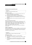
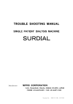
1
Model 2181
Electric Powered Turntable
3-Meter and 4-Meter
User Manual
ETS-Lindgren L.P. reserves the right to make changes to any products herein to improve
functioning or design. Although the information in this document has been carefully reviewed and
is believed to be reliable, ETS-Lindgren does not assume any liability arising out of the
application or use of any product or circuit described herein; nor does it convey any license under
its patent rights nor the rights of others. All trademarks are the property of their respective
owners.
©Copyright 2007 by ETS-Lindgren L.P. All Rights Reserved. No part of this document may
be copied by any means without written permission from ETS-Lindgren L.P.
Trademarks used in this document: The ETS-Lindgren logo is a trademark of ETS-Lindgren L.P.
Revision Record
MANUAL,2181 Turntable Series, 3M & 4M | Part #399289, Rev. A
Revision
Description
Date
A
Initial Release
February, 2007
Internet Address
http://www.ETS-Lindgren.com
USA
1301 Arrow Point Drive
Cedar Park, TX 78613 USA
Tel: +1.512.531.6400
Fax: +1.512.531.6500
Email: [email protected]
Finland
Mekaanikontie 1, 27510
Eura, Finland
Tel: +358.2.838.330
Fax: +358.2.865.1233
Email: [email protected]
Japan
4-2-6, Kohinata
Bunkyo-ku, Tokyo 112-0006 Japan
Tel: +81.3.3813.7100
Fax: +81.3.3813.8068
Email: [email protected]
China
B507A Technology Fortune Center
No. 8 Xue Qing Road
Haidian District
Beijing Postcode: 100083 China
Tel: +86.010.827.30877
Fax: +86.010.827.55307
Email: [email protected]
ii
|
Table of Contents
Safety Symbol Definitions ..................................................................................... v
General Safety Considerations ............................................................................ vi
Waste Electrical and Electronic Equipment (WEEE) Directive............................ vii
1.0 Introduction .....................................................................................................9
2.0 Receiving Your Order ...................................................................................11
Unpacking and Acceptance .................................................................................................... 11
Service Procedures................................................................................................................. 11
3.0 Maintenance .................................................................................................13
Recommended Maintenance Schedule .................................................................................. 13
Replacement and Optional Parts ............................................................................................ 13
4.0 Model 2181 Turntable Configuration.............................................................15
Standard Configuration ........................................................................................................... 15
Model 2090 Series Multi-Device Positioning Controller.......................................................... 16
Optional Items ......................................................................................................................... 16
5.0 Specifications................................................................................................19
Electrical Specifications .......................................................................................................... 19
Mechanical Specifications....................................................................................................... 19
6.0 Turntable Installation Considerations............................................................21
Before You Begin—Precautions ............................................................................................. 21
Power and Signal Lines .......................................................................................................... 22
Outdoor Installations ............................................................................................................... 22
7.0 Assembly and Installation Instructions ..........................................................23
Floor Flange Installation.......................................................................................................... 25
IR Repeater Installation........................................................................................................... 27
8.0 Electrical Installation .....................................................................................29
Connecting the Model 2090 Controller ................................................................................... 30
9.0 Operation ......................................................................................................31
Editing Positioning Controller Configuration Parameters........................................................ 31
Setting Travel Limits................................................................................................................ 32
Turntable Encoder Calibration ................................................................................................ 34
Changing Rotation Speed....................................................................................................... 35
Variable Speed Settings.......................................................................................................... 36
Speed Selection ...................................................................................................................... 36
GPIB Commands .................................................................................................................... 37
|
iii
Appendix A: Warranty Policy for Standard EMCO Brand Products.....................39
Scope and Duration of Warranties.......................................................................................... 39
Warranty Exclusions ............................................................................................................... 39
Buyer’s Remedies ................................................................................................................... 40
Appendix B: EC Declaration of Conformity .........................................................43
iv
|
Safety Symbol Definitions
This product and related documentation must be reviewed for familiarization with
safety markings and instructions prior to operation of the product.
Safety Symbol
!
OR
Definition
REFER TO MANUAL—When the product is marked with this symbol
refer to the instruction manual for additional information. If the
instruction manual has been misplaced, go to www.ets-lindgren.com for
downloadable files or contact ETS-Lindgren customer service.
HIGH VOLTAGE—Indicates the presence of hazardous voltage.
Unsafe practice could result in several personal injury or death.
OR
PROTECTIVE EARTH GROUND (SAFETY GROUND)—Indicates
protective earth terminal. Uninterruptible safety earth ground from the
main power source to the product input wiring terminals, power cord or
supplied power cord set shall be provided.
CAUTION
WARNING
CAUTION—Denotes a hazard. Failure to follow instructions could result
in minor personal injury and/or property damage. Text that follows the
symbol will provide proper procedures.
WARNING—Denotes a hazard. Failure to follow instruction could result
in severe personal injury and/or property damage. Text that follows the
symbol will provide proper procedures.
|
v
General Safety Considerations
Safety Symbol
Definition
Read this manual completely and refer to drawings at the end of the
manual before beginning the installation. This equipment should be
installed and operated only by qualified personnel.
QUALIFIED PERSONNEL ONLY
•
The electrical installation of this product should be
accomplished by an individual who is authorized to so do by the
appropriate local authority. The installation should be in
compliance with local electrical safety codes.
•
Only qualified personnel should operate or service this
equipment.
BEFORE POWER IS APPLIED TO THIS INSTRUMENT, GROUND IT
PROPERLY through the protective conductor of the AC power cable to
a power source provided with protective earth contact. Any interruption
of the protective (grounding) conductor, inside or outside of the
instrument, or disconnection of the protective earth terminal could result
in personal injury.
WARRANTY
WARRANTY
BEFORE SERVICING: CONTACT ETS-LINDGREN
(+1.512.531.6400)—Servicing or modifying the unit without
ETS-Lindgren authorization may void your warranty. If an attempt to
service the unit must be made, disconnect all electrical power prior to
beginning. Voltages exist at many points within the instrument that
could, if contacted, cause personal injury. Only trained service
personnel should perform adjustments and/or service procedures upon
this instrument. Capacitors inside this instrument may still be charged
even when the instrument is disconnected from the power source.
•
Do not make any modifications to this unit without consulting
the factory directly.
•
Only use replacement parts and fasteners ordered directly from
the factory.
STAY CLEAR of moving components during operation of equipment.
vi
|
Safety Symbol
Definition
Do not, at any time, place hands or feet in the vicinity of the drive pinion
on the turntable.
Regularly inspect all equipment and conduct scheduled maintenance in
accordance with the factory recommendations provided.
Waste Electrical and Electronic Equipment (WEEE) Directive
(European Union) At end of useful life, this product should be deposited
at an appropriate waste disposal facility for recycling and disposal. Do
not dispose of with household waste.
|
vii
This page intentionally left blank.
viii
|
1.0 Introduction
The ETS-Lindgren Model 2181 is an electric-powered turntable platform system
designed for use with the Model 2090 Series Multi-Device Positioning Controller
for EMI compliance testing. The Model 2181 turntable is available in 3-meter and
4-meter sizes, both designed for indoor or outdoor use.
The Model 2181 turntable utilizes a pinion and gear drive with a gear reducer and
electric motor located beneath the platform. The conductive metal top of the
turntable is outfitted with a continuous ground brush to electrically couple it to the
ground plane. The sectional turntable top provides easy access in the event that
service is required. A shielded enclosure contains the electronics for the system.
Signal I/O from the turntable to the Model 2090 controller uses fiber optic cable.
The ground brushes are attached directly to the turntable and are in continuous
contact with the wear strip mounted on the floor flange. The brushes point
outward from the turntable.
The bearing on which the turntable rotates has the drive teeth cut directly on the
outside and will easily support most Equipment Under Test (EUT). Casters
located beneath the table surface provide support for a cantilevered load.
Leveling screws are located at each caster, between the casters, and in the
center section of the assembly for ease in matching height on an uneven ground
plane.
To prevent over-travel of the turntable in either direction of movement, hard limits
are provided in the form of pins that actuate switches located below the tabletop.
These pins allow limits to be set and allow as much as two full rotations. Rotation
speed can be varied from the front panel of the Model 2090 controller or through
the IEEE-488 interface bus.
Introduction
|
9
This page intentionally left blank.
10
|
Introduction
2.0 Receiving Your Order
Unpacking and Acceptance
Step 1. Upon delivery of your order, inspect the shipping container(s) for
evidence of damage. Record any damage on the delivery receipt before signing
it. In case of concealed damage or loss, retain the packing materials for
inspection by the carrier.
Step 2. Remove the product from its shipping container(s). Save the container(s)
and any protective packing materials for future use.
Step 3. Check all materials against the packing list to verify that the equipment
you received matches what was ordered. If you find any discrepancies, note
them and call ETS-Lindgren Customer Service for further instructions.
Make sure you are satisfied with the contents and condition of your order prior to
placing the product into service.
Service Procedures
To return a system or system component for service:
Step 1. Contact ETS-Lindgren Customer Service to obtain a Service Request
Order (SRO).
Step 2. Briefly describe the problem in writing. Give details regarding the
observed symptom(s) or error codes, and whether the problem is constant or
intermittent in nature. Please include the date(s), the service representative you
spoke with, and the nature of the conversation. Include the serial number of the
item being returned.
Step 3. Package the system or component carefully. If possible, use the original
packing materials to return a system or system component to ETS-Lindgren at
the following address:
ETS-Lindgren
Attn: Service Department
1301 Arrow Point Drive
Cedar Park, TX, USA 78613
Phone: +1.512.531.6400
Customer Service: +1.512.531.6498
www.ets-lindgren.com
Receiving Your Order
|
11
This page intentionally left blank.
12
|
Receiving Your Order
3.0 Maintenance
Recommended Maintenance Schedule
Regular maintenance will prolong the effective operation and reliability of your
turntable. Follow the recommended schedule for 6- and 12-month service.
CAUTION
Do not perform maintenance while the turntable is operating.
6-MONTH SERVICE
•
Lubricate the casters with good quality bearing grease.
•
Check the gearbox for fluid leakage. A collection of slight film is normal, but
puddles of fluid are not normal. The gearbox is lubricated and sealed at the
factory. Under normal conditions, the gearbox should not require servicing
during its life.
12-MONTH SERVICE
•
Lubricate the main bearing race with a grease gun containing good quality
bearing grease. The grease fittings are located inside the race, 90 degrees
apart, beneath the top. Three discharges from the grease gun in each fitting
are adequate.
•
Lubricate the gear teeth with good quality grease.
Replacement and Optional Parts
Use the following tables to order replacement or optional parts for the
Model 2181 turntable.
Replacement Part
Part Number
Turntable assembly
For a list of all turntable parts, see the
drawings located in the back pocket of
this manual.
Model 2090 Series Multi-Device
Positioning Controller
2090
Table 1:
Replacement Parts List
Maintenance
|
13
Optional Part
Part Number
IR Remote Controller
707030
NEMA connectors for slip ring
103441
Schuko connectors for slip ring
103351
Table 2:
14
|
Maintenance
Optional Parts List
4.0 Model 2181 Turntable Configuration
Standard Configuration
TURNTABLE ASSEMBLY
Featuring continuous or non-continuous operation, the turntable assembly
includes:
•
Three-phase electric motor unit
•
Heavy-duty variable speed drive system
•
Conductive sectional top
•
Convenient rotational limit adjust switches
•
Limit override feature
•
Ground ring assembly with ground brush and floor flange
•
Ten-meter fiber optic control cables
•
Overall height 40.0 cm (15.75 in)
•
Sectional top for easy service access
•
Full-supporting leveling screws
Additionally, the turntable is infrared compatible, and can be used with an
optional ETS-Lindgren Infrared Remote Controller (IR remote). For more
information on using an IR remote, see Infrared Remote Controller on page 16.
SHIELD ROOM FEED-THROUGH
Routes the fiber optic control cable from the control room to the shield room,
maintaining satisfactory shielding attenuation. The unit is made of brass for
conductivity and provides attenuation of greater than 100 dB at 10 GHz. A single
22.25-mm (.875-in) hole is required for mounting.
Model 2181 Turntable Configuration
|
15
Model 2090 Series Multi-Device Positioning Controller
The Model 2090 controller is a separate component required for
Model 2181 turntable operation.
The Model 2090 Series Multi-Device Positioning Controller provides control for
two separate devices, such as ETS-Lindgren towers and turntables, plus the
control of four auxiliary devices. The Model 2090 controller includes a GPIB bus
and is compatible with most popular software, and electronically controls speed
adjustment through the GPIB interface or front panel.
Optional Items
INFRARED REMOTE CONTROLLER
The Model 2181 turntable is infrared compatible, and can be used with a
universal remote control programmed to a specific protocol, such as the
ETS-Lindgren Infrared Remote Controller (IR remote).
The IR remote communicates with an infrared receiver in the
Model 2181 motor base through an IR repeater installed in the floor near the
turntable. See IR Repeater Installation on page 27 for instructions on installing an
IR repeater.
16
|
Model 2181 Turntable Configuration
SLIP RING
Allows continuous rotation of the turntable through the latest technology in
mercury slip rings, and either Schuko or NEMA connectors can be ordered with
the slip ring. The current rating for the standard electrical assembly is
20 amperes. Contact ETS-Lindgren for custom requirements on slip rings.
EUT POWER OUTLETS
Receptacles are usually mounted on the base of the turntable at the center axis
point. These receptacles can be custom mounted, flush with the tabletop on
some turntables. Contact ETS-Lindgren for information.
MOUNTED LINE IMPEDANCE STABILIZATION NETWORK
A Line Impedance Stabilization Network (LISN) can be mounted to the underside
of some turntables. This option is only practical on larger turntables with sufficient
clearance.
ADDITIONAL FIBER OPTIC CABLES
Additional lengths of fiber optic cable may be ordered.
Model 2181 Turntable Configuration
|
17
This page intentionally left blank.
18
|
Model 2181 Turntable Configuration
5.0 Specifications
Electrical Specifications
Drive Speeds:
Variable
Nominal AC Voltage:
200–230 VAC
Input Frequency:
50/60 Hz
Current Rating:
15 amp service
Current Draw:
< 10 amps
RPM:
.5 – 2.0
Phase:
Single (1)
Mechanical Specifications
Diameter:
3.0 m
9.84 ft
4.0 m
13.12 ft
Nominal Height:
40.0 cm
15.75 in
40.0 cm
15.75 in
Required Pit Diameter:
306.3 cm ± 1.0 cm
120.6 in ± .40 in
406.4 cm ± 1.0 cm
160.0 in ± .40 in
Top Construction
Sectional Aluminum
Sectional Aluminum
Distributed Load Rating:
4000 kg
8818 lb
6000 kg
13227 lb
Distributed Load Rating applies when:
•
Load is evenly distributed on top;
•
No point loads under .19 sq m (2.0 sq ft) should exceed 100 kg (220 lb);
•
And not over 28.5 kg (62.8 lb) should be applied to a 45-degree
segment at the table outer edge.
Specifications
|
19
This page intentionally left blank.
20
|
Specifications
6.0 Turntable Installation Considerations
Prior to assembly, installation, and operation, read Safety Symbol Definitions on
page v and General Safety Considerations on page vi.
Pre-planning is essential for a successful installation. Discuss your requirements
will your sales representative and request dimensional drawings prior to site
construction.
Before You Begin—Precautions
Read this manual completely before starting installation. This
equipment should be installed and operated only by qualified
personnel.
The electrical installation of this product should be accomplished by an
individual who is authorized to so do by the appropriate local authority.
The installation should be in compliance with local electrical safety
codes.
Do not attempt to service unless qualified to do so. As with any
electrical equipment, make sure unit electrical power has been
disconnected and secured when performing scheduled maintenance or
adjustments.
Do not make any modifications to this unit without consulting the factory
directly.
WARRANTY
Regularly inspect all equipment and conduct scheduled maintenance in
accordance with the factory recommendations provided.
Only use replacement parts and fasteners ordered directly from the
factory.
Stay clear of all moving components on this equipment.
Do not operate turntable while someone is physically on the turntable
top.
Do not, at any time, place hands or feet in the vicinity of the drive pinion
on the turntable.
Turntable Installation Considerations
|
21
Power and Signal Lines
CONDUIT
Power and signal line paths should be planned in advance. Conduit should be in
place before pouring concrete or installing the ground plane. Consider the size of
the cable bundle when selecting conduit diameter.
ELECTRICAL CONSIDERATIONS
A qualified and licensed electrical contractor should install power lines, and the
installation should comply with all applicable regulatory agencies. A dedicated
circuit should be used, with the shortest distance possible between the power
source and the turntable.
ACCESS
An access area beneath the turntable is advisable for large diameter
installations. A service switch should be installed to deactivate the turntable
during service.
Outdoor Installations
DRAINAGE
A centerline drain of at least 15 cm (6 in) must be installed to provide proper
drainage during rainstorms and other moisture-collecting situations.
COLD CLIMATE CONDITIONING
The oil used in the gear assemblies will congeal at 2 degrees C (28 degrees F).
Turntables operated in these temperatures should include a heat source or
dehumidifier, or both.
22
|
Turntable Installation Considerations
7.0 Assembly and Installation Instructions
Proper installation of the turntable directly affects performance. The installation of
turntables two meters and larger will be performed by factory installation
specialists or individuals authorized by ETS-Lindgren to perform such work. The
following installation information is included only to provide an informational
overview of the installation process.
Prior to assembly and installation, review the drawings located in the back
pocket of this manual.
1. Uncrate all parts and check for shipping damage. Create a clear area to
safely assemble the turntable unit. Do not discard any packing material
until unit is fully assembled.
2. Remove the ½-13 flat head screws from the center of the turntable.
3. Install the eye-bolts (included) into the appropriate holes located on the
center top sections, and then attach lifting chains or slings (not included)
through the eye-bolts.
CAUTION
Only qualified personnel should use a forklift or other lifting
machinery.
4. Using a forklift or other appropriate lifting machinery, remove the
turntable top.
5. Remove the eye-bolts from the turntable top, and install them in the
appropriate holes located on the bearing support.
6. Using a forklift or other appropriate lifting machinery, place the turntable
bottom bearing support section into position. Remove the eye-bolts from
the bearing support.
7. Remove the drive pinion to allow manual rotation of the turntable.
8. To install the turntable into a pit or floor cut-out, first center and level the
turntable assembly. The drawings located in the back pocket of this
manual illustrate the placement of floor plates and leveling screws
required to anchor and level the turntable. Your installation specialist
may make slight adjustments to accommodate your particular site.
Assembly and Installation Instructions
|
23
Make sure the diameter of the cutout in the floor matches the dimensions
specified in the assembly drawings located in the back pocket of this manual.
9. Install the floor plates and leveling screws, and then adjust all of the
leveling screws to level the entire turntable.
CAUTION
Turn off the electrical breaker located on the drive box assembly.
Make sure power is off and secured before proceeding.
10. After the turntable is leveled, lock the height of the turntable into place by
tightening the lock-nuts that accompanied the leveling screws.
11. Anchor the turntable though the anchor holes with the included bolts.
12. Confirm the electrical breaker is off, and then re-install the drive pinion.
CAUTION
Electrical connection is subject to local electrical codes, and
should only be performed by a qualified electrician.
13. Connect the fiber optic control cable and install the power connection
according to local electrical code. See Electrical Installation on page 29
for electrical installation guidelines.
CAUTION
Keep all body parts away from the drive pinion when the
turntable is energized.
14. Turn on the electrical breaker located on the drive box assembly.
15. To verify proper operation, rotate the turntable using the controller.
16. To set travel limits, see Setting Travel Limits on page 32.
17. Follow the instructions in the next section, Floor Flange Installation, to
install the ground ring assembly.
18. With the turntable running in the clockwise (CW) or counterclockwise
(CCW) direction, use the included key to adjust the speed of the
turntable to the desired speed.
19. Using the ½-13 flat head screws removed in step 2, re-install the
turntable top onto the drive section.
24
|
Assembly and Installation Instructions
Floor Flange Installation
Prior to installing the floor flanges, review the drawings located in the back
pocket of this manual.
The ground ring assembly includes a set up floor flanges that interface with the
brush ring located on the perimeter of the turntable. The floor flanges provide
constant electrical contact with the ground plane, and are usually installed with
the turntable.
Mounting methods vary according to user specifications. Clearance holes are
provided at evenly spaced intervals along the outside perimeter of the floor
flanges to attach to a customer supplied ground plane.
Installing the ground ring assembly requires these tools:
•
Three ¼-in spacers
•
Hand drill
•
5/32-in drill bit
•
#3 Phillips drive bit
•
Small square
•
#14 x 1 wood/metal screws
The turntables each have six floor flange pieces. All flanges are pre-cut at the
factory for a drop-in fit.
A 3-meter Model 2181 turntable is depicted in the following. The turntable top is
shown as a partial cut-away to provide a view of internal components.
Assembly and Installation Instructions
|
25
1. When attaching the ground ring, first center and level the turntable
assembly into the turntable pit.
2. Install the floor flanges around the turntable. A gap of 5/16 inch (0.79 cm)
to 7/16 inch (1.11 cm) should be maintained around the turntable. Match
drill with the floor and install ¼-20 inch flat head screws.
3. Install a wear strip on the inside of the floor flange by aligning it with the
top of the flange, and aligning the pre-drilled mounting holes in the strip
to 1.00 inch (2.54 cm) from the bottom of the flange.
4. Make sure that the wear strip covers the full circumference of the flange,
and then trim the wear strip to size.
5. Using the pre-drilled holes on the wear strip as a template, drill holes
through the floor flange.
6. Secure the wear strip to the floor flange with 6-32 x 3/8-in thread cutting
screws (provided).
7. Apply conductive grease (provided) on the wear strip along the brush
contact area, approximately one inch to two inches from the top of the
strip.
26
|
Assembly and Installation Instructions
IR Repeater Installation
INSTALLATION ASSEMBLY COMPONENTS
•
Infrared sensor
•
Mounting collar
•
IR-100 control unit
•
IR flasher LED
•
9-12VDC power supply
•
Connection cable
•
Flathead mounting screws
REQUIRED TOOLS FOR INSTALLATION
•
Electric drill
•
1-inch hole saw to create a
•
1/16-inch drill bit
•
Small flat blade screwdriver
•
Phillips #2 bit driver
•
Adhesive tape
INSTALLATION STEPS
1. Choose a location for the IR infrared sensor that is away from traffic.
2. Using a 1-inch hole saw, cut an opening in the floor for the IR sensor.
3. Connect the V+, GND, and SIG wires to the IR sensor as shown in the
diagram, and feed the cable through the hole.
Assembly and Installation Instructions
|
27
4. Use the 1/16-inch drill bit and four flathead mounting screws to mount
the IR sensor collar.
5. Connect the V+, GND, and SIG wires from the IR sensor to the
IR-100 control unit as shown in the diagram.
6. Using adhesive tape, attach the IR flasher LED directly over the IR input
on the motor control box.
7. Connect the IR flasher to port 1 on the IR-100 control unit.
8. Plug the 9-12VDC power supply into the power connector on the
IR-100 control unit, and then plug the power supply into a 120 VAC
outlet.
28
|
Assembly and Installation Instructions
8.0 Electrical Installation
CAUTION
Electrical installation must be performed by a qualified
electrician, and in accordance with local and national electrical
standards.
The Model 2181 turntable is configured to operate using 200-230 VAC, single
phase, 50/60 Hz service. It is recommended to operate at this voltage level to
reduce the surge currents necessary to power an electric motor.
1. The branch circuit supplying power to the motor base should be
protected from excess current according to local electrical codes. An
integral circuit breaker is mounted inside the main bearing on one of the
bearing support blocks. The circuit breaker is specifically designed for
the inductive load presented by the electric motor.
2. Make sure the conductor size is adequate for the motor load and the
distance from the mains source. Improperly sized conductors will lead to
a high voltage drop in the power conductors and cause reduced starting
torque and premature motor failure.
3. The motor base assembly is provided with a non-terminated flexible
conduit with input power leads exposed. The flexible conduit is to be
terminated into a junction box fitted on or near the motor base. Terminate
the power leads of the motor base assembly according to local electrical
code requirements. Following is the conductor color code:
Brown: AC high
Blue: AC neutral
Green/Yellow: Protective earth/safety ground
Connect the fiber optic control cable and install the power connection according
to local electrical code. See the Model 2090 Series Multi-Device Controller
Manual for information on connecting the fiber optic cable. After the fiber optic
cable is installed, secure it with a wire tie to one of the leveling screws.
To feed the fiber optic connectors through the waveguide in a chamber, it may be
necessary to remove part of the protective sheath. This removal allows the
connectors to fit through the hole without excessively bending the fiber optic
cable. Find and mark the spot where you will need to remove the sheath. Use a
sharp knife to carefully cut around the outside of the sheath at each end of the
defined area. Cut very lightly to avoid cutting into the fiber optic cables, then
bend the sheath back and forth to expose the fiber optic cables.
Electrical Installation
|
29
Next, make a cut down the length of sheath area, being careful not to cut into
fiber optic cable. Inside the sheath are two pieces of white string. Find the string
and use it to split the sheath open. Insert the fiber optic cable into the waveguide.
Connecting the Model 2090 Controller
Any combination of primary devices (towers, turntables, reverberation paddles,
MAPS, and so on) can be connected to the two device interface ports located on
the rear panel of the Model 2090 Series Multi-Device Positioning Controller. For
easy set up of an EMC facility, it is recommended that the turntable be connected
to the Device 2 port. The default settings for the controller are for a tower
connected to the Device 1 port and a turntable connected to the Device 2 port.
Primary device connection is accomplished with a dual fiber optic cable included
with the device. This cable terminates into two ST connectors that are identical at
both ends. The cable is symmetrical, so either end can be connected to the
controller. A fiber optic cable connected to the IN port of a device should be
connected to the primary OUT port of the motor base at the other end. Similarly,
a fiber optic cable connected to the OUT port of the device should be connected
to the primary IN port of the motor base at the other end. Older motor base
designs have only one fiber optic connector pair, but the newer motor base
interface provides a secondary interface reserved for future expansion.
Fiber optic cabling for each device should not hang unsupported from the rear
panel of the controller. The fibers and connectors are easily broken if twisted or
bent. Keep the fiber optic cables as straight as possible from the connector to
the protective sheath.
Using the Model 2090 controller or optional Infrared Remote Controller
(IR remote), rotate the motor base shaft to verify proper operation. Run the
motor base down to the lower limit counterclockwise, and then back it off from
the lower limit a small amount. The previous step will help when it is time to set
the rotation limits for the turntable.
CAUTION
30
|
The soft rotational limits in the Model 2090 controller must be
set. Make sure the travel limit settings will not cause damage to
user installed cables and equipment mounted on the table.
Electrical Installation
9.0 Operation
If you are unfamiliar with the operation of the controller, see the
Model 2090 Series Multi-Device Controller Manual. A manual is included with
each positioning controller shipment and is also available for download from
www.ets-lindgren.com.
With the assembly of the turntable complete, the Model 2090 Series Multi-Device
Positioning Controller must be connected to the unit and power applied to both
the motor base and controller in order to continue. See the Model 2090 controller
manual for information on connecting the fiber optic cable.
Use the Model 2090 controller to check the clockwise (CW) and
counterclockwise (CCW) rotation in both directions by a few degrees. The
position in degrees increases (+) in the CW direction and decreases (-) in CCW
direction.
The turntable is calibrated in the factory to read out 360 degrees (plus or minus
1 degree) for one complete revolution. If the turntable is not within this range, the
unit can be re-calibrated using the instructions in Turntable Encoder Calibration
on page 34.
Editing Positioning Controller Configuration Parameters
Key
Function
PARAM
To edit a configuration parameter:
• Press PARAM key to display the current parameter.
• Press PARAM key repeatedly to scroll through the parameter list,
displaying each parameter.
STEP (INC/DEC)
To scroll up or down the parameter list while viewing a parameter.
Reduces the effort necessary to scan through a long parameter list
using the PARAM key.
LIMIT/POSITION
Press any of the LIMIT/POSITION selection keys to return the display
to that selection.
Press any of the remaining motion keys to return the display to the
current position and execute that motion.
Press the PARAM key again to return to the last displayed parameter
in the list, allowing easy transition between parameter adjustment and
device operation.
Operation
|
31
Key
Function
INCRM, DECRM,
or ENTER
Once the desired limit, position, or parameter is visible in the display
window, press INCRM, DECRM, or ENTER to toggle into edit mode.
The lowest adjustable digit will flash on and off.
LOCAL
Press the LOCAL key for that device to switch the flashing digit to the
next higher digit. In this way, it is possible to rapidly adjust any digit of
a multi-digit parameter or limit.
Setting Travel Limits
The Model 2181 turntable is fitted with mechanically actuated, or hard limit,
switches. These switches are adjustable to allow for limited travel beyond zero
and 360 degrees. Actuation pins are placed in the turntable top to engage the
limit switch mechanism. The limit switch mechanism is designed so that the
amount of travel is dictated by the pin position in the turntable top.
Turntable Limit Switch
The default configuration allows for travel between -45 degrees and
+405 degrees.
1. Remove all pins around the turntable and the ETS-Lindgren logo access
panel.
2. Move the turntable so that the access compartment is directly above the
limit switch.
32
|
Operation
3. Set the mechanism to the CCW armed position and insert actuation pins
in the holes on either side of the mechanism 45 degrees away.
4. Set the current position displayed by the controller to 000.0 degrees.
5. Test the lower limit by holding down the DEC key, which allows the
turntable to travel past the soft limit. The turntable should engage the
lower hard limit between -35 and -55 degrees. You can also test the
upper limit by holding down the INC key until the upper limit is engaged
between 395 and 415 degrees.
If non-continuous operation is desired, properly set the soft limits in the
controller.
To set the CCW rotational limit for the turntable:
1. Press the DOWN/CCW key under LIMIT. The indicator above the key will
illuminate.
2. Set the limit by pressing the INCRM and DECRM keys under LIMIT until
the desired limit is shown on the display.
3. Press the ENTER key.
To set the CW rotational limit for the turntable:
1. Press the UP/CW key under LIMIT. The indicator above the key will
illuminate.
2. Set the limit by pressing the INCRM and DECRM keys under LIMIT until
the desired limit is shown on the display.
3. Press the ENTER key.
WARNING
Make sure the current travel limit settings will not cause
damage to existing cables and equipment located beneath the
turntable.
If continuous operation is desired, the Model 2090 controller permits easy
configuration to this type of operation from the front panel or through the
IEEE-488 interface bus. For more information, see the Model 2090 Series
Multi-Device Controller Manual. The limit pins should also be removed from the
turntable top to allow for continuous operation.
Operation
|
33
Turntable Encoder Calibration
Parameter C, the encoder calibration parameter, calibrates the encoder counts to
the rotation of the turntable. For the Model 2181 turntable, parameter C must be
set to 3660. This setting is used to convert the encoder count values returned
from a motor base into the corresponding centimeter or degree position reading.
For turntables, this represents the number of encoder counts per revolution.
If the given value does not work correctly, the encoder calibration value can be
determined using the following procedure:
1. Set the encoder calibration value to 3600.
2. Make sure the turntable is positioned to allow more than a full revolution
of travel in the CW direction. Use the STEP keys to run the turntable CW
a few degrees to remove any play in the turntable.
3. Using masking tape, mark the current location of the turntable against
the ground ring, and set the current position reading to 000.0.
4. Using the STEP keys, rotate the turntable CW until it is again aligned
with the mark on the ground ring. For best results, the last motion should
always be in the CW direction to account for any play in the gearing
between the motor and encoder.
5. Record the reading of the display, ignoring the decimal point. For
example, 360.0 would be 3600. This is the encoder calibration value.
If the value is below 3600, the resolution of the encoder is low and the
controller will not provide 0.1-degree resolution, even though the display
shows that digit. If the value is past 9999, the encoder has too many counts
per meter and the controller cannot correct for it. In this case, contact
ETS-Lindgren for assistance.
6. Enter the encoder calibration value and reset the limits and position
information.
7. Test the turntable by moving it a complete revolution and comparing the
alignment marks. It may be necessary to adjust the encoder calibration
value up or down slightly depending on the result.
34
|
Operation
When scanning between limits, it is not uncommon to have a small
discrepancy between the absolute position of the table and the display on the
controller. This is because reversing the direction of rotation reverses any
gear play between the encoder and the table top, allowing that play to be
visible in the positioning accuracy.
TURNTABLE CALIBRATION EXAMPLE
•
The turntable is set at the 0 degree position. A piece of tape is placed on the
edge of the turntable to line up with the edge of the gearbox cover. The
turntable is stopped when the tape travels exactly 360 degrees around. The
display on the controller now reads 356.3 degrees, which is recorded.
•
The table is rotated CCW back to zero. The parameter button is set on the
C setting. The C digits display 3430. A new C setting is now calculated:
New C = (356.3 / 360) x 3430 = 3395 (rounded)
•
Decrement the C parameter to 3395 and press ENTER. Press the
current position button to get back to operation mode.
•
The table is rotated from 0 to 360 and the mark is now within one degree of
being one full turntable revolution. Calibration is complete.
Changing Rotation Speed
The Model 2181 turntable is equipped with a variable speed drive. Firmware
revision 3.11 or higher must be installed in the Model 2090 controller for proper
operation of the Model 2181. The revision level is displayed on the front panel
display during startup of the Model 2090 controller. If the controller does not have
this revision or a later revision installed, contact ETS-Lindgren for an upgrade.
To select one of the four speeds, use the POLAR/SPEED button to toggle
through the speed options. It is necessary to set the controller parameters to
configure the controller to properly control the motor base. See the
Model 2090 Series Multi-Device Controller Manual for information on setting the
parameters.
Operation
|
35
Variable Speed Settings
The Model 2090 controller parameters S1-S8 control the variable speed settings
for the turntable. These parameters are the continuous variable speed settings
for each of the four speed selections described in the next section,
Speed Selection. Each of these parameters can be set to any value from 1 to
255, with the resulting turntable speed being roughly an S/255 fraction of the
maximum speed. For any variable speed drive, there is a minimum speed at
which the motor will operate. For the Model 2181 turntable this minimum speed
setting is between 30 and 75, and should correspond to a value of 0.5 RPM or
less. Below this setting, the motor will not be able to cause rotation, but will be
active until a Motor Not Moving error (E002) occurs.
WARNING
Do not operate the turntable in a stalled condition. Doing so
may cause damage to the drive unit and will void your
warranty. Always make sure that the minimum speed setting
specified in the S1-S8 parameters is above the minimum value
at which your turntable will rotate under normal load.
Speed Selection
For the variable speed turntable, the Polarization/Flotation button provides the
ability to cycle between eight preset speeds. For each press of the button, the
turntable will change to the next speed setting. The polarization LEDs will light to
indicate the speed selection as shown in the following:
Speed 1: Both off
Speed 2: Top on, bottom off
Speed 3: Top off, bottom on
Speed 4: Both on
Speed 5: Both off
Speed 6: Top on, bottom off
Speed 7: Top off, bottom on
Speed 8: Both on
Each speed setting has an individual overshoot compensation value to provide
overshoot correction.
36
|
Operation
GPIB Commands
The following GPIB commands have been added or modified:
Sn: Select speed
•
n = 1-4 for a variable speed turntable
S?: Query speed selection
•
Returns 1-4 for a variable speed turntable
SSn: Set speed value
•
n = 1-4
•
Command is valid only for a variable speed turntable
•
Valid speed values are 1-255
•
Command Usage: SSn <Speed>
•
Example: Output 708, SS1 196
SSn?: Query speed value
•
n = 1-4
•
Command is valid only for a variable speed turntable
•
Returns a speed value 1-255
•
Command Usage: SSn?
•
Example: Output 708, SS2?
Operation
|
37
This page intentionally left blank.
38
|
Operation
Appendix A: Warranty Policy for Standard EMCO Brand Products
SCOPE AND DURATION OF WARRANTIES
Seller warrants to Buyer that the Standard EMCO Brand Products Excluding 5211 &
5220 be (1) free from defects in material, manufacturing workmanship, and title, and (2)
conform to the Seller’s applicable product descriptions and specifications, if any,
contained in or attached to Seller’s quotation. If no product descriptions or specifications
are contained in or attached to the quotation, Seller’s applicable product descriptions and
specifications in effect on the date of shipment shall apply. The criteria for all testing shall
be Seller’s applicable product specifications utilizing factory-specified calibration and test
procedures and instruments.
All product warranties, except the warranty of title, and all remedies for warranty failures
are limited in time as shown in the table below.
Product Warranted
Duration of Warranty Period
Standard EMCO Brand Products
Excluding 5211 & 5220
2 Years
Any product or part furnished to Buyer during the warranty period to correct a warranty
failure shall be warranted to the extent of the unexpired term of the warranty applicable to
the repaired or replaced product.
The warranty period shall commence on the date the product is delivered to Buyer;
however, if Seller assembles the product, or provides technical direction of such
assembly, the warranty period for such product shall commence on the date the
assembly of the product is complete. Notwithstanding the foregoing, in the event that the
assembly is delayed for a total of thirty (30) days or more from the date of delivery for any
reason or reasons for which Seller is not responsible, the warranty period for such
product may, at Seller’s options, commence on the thirtieth (30th) day from the date such
product is delivered to Buyer. Buyer shall promptly inspect all products upon delivery. No
claims for shortages will be allowed unless shortages are reported to Seller in writing
within ten (10) days after delivery. No other claims against Seller will be allowed unless
asserted in writing within thirty (30) days after delivery (or assembly if the products are to
be assembled by Seller) or, in the case of alleged breach of warranty, within the
applicable warranty period.
WARRANTY EXCLUSIONS
Except as set forth in any applicable patent indemnity, the foregoing warranties are
exclusive and in lieu of all other warranties, whether written, oral, express, implied, or
statutory. EXCEPT AS EXPRESSLY STATED ABOVE, SELLER MAKES NO
WARRANTY, EXPRESS OR IMPLIED, BY STATUTE OR OTHERWISE, WHETHER OF
MERCHANTABILITY OR FITNESS FOR ANY PARTICULAR PURPOSE OR USE OR
OTHERWISE ON THE PRODUCTS, OR ON ANY PARTS OR LABOR FURNISHED
DURING THE SALE, DELIVERY OR SERVICING OF THE PRODUCTS. THERE ARE
NO WARRANTIES WHICH EXTEND BEYOND THE DESCRIPTION ON THE FACE
HEREOF.
Warranty coverage does not include any defect or performance deficiency (including
failure to conform to product descriptions or specifications) which results, in whole or in
Warranty Policy for Standard EMCO Brand Products
|
39
part, from (1) negligent storage or handling of the product by Buyer, its employees,
agents, or contractors, (2) failure of Buyer to prepare the site or provide an operating
environmental condition in compliance with any applicable instructions or
recommendations of Seller, (3) absence of any product, component, or accessory
recommended by Seller but omitted at Buyer’s direction, (4) any design, specification, or
instruction furnished by Buyer, its employees, agents or contractors, (5) any alteration of
the product by persons other than Seller, (6) combining Seller’s product with any product
furnished by others, (7) combining incompatible products of Seller, (8) interference with
the radio frequency fields due to conditions or causes outside the product as furnished by
Seller, (9) improper or extraordinary use of the product, or failure to comply with any
applicable instructions or recommendations of Seller, or (10) acts of God, acts of civil or
military authority, fires, floods, strikes or other labor disturbances, war, riot, or any other
causes beyond the reasonable control of Seller. This warranty does not cover (1) contact
fingers or replacements unless loss is caused by a defect in material or manufacturing
workmanship within the scope of this warranty (2) items designed to be consumable and
(3) removal and reconstruction of walls, partitions, ceilings and other facility costs arising
from repair or replacement of the product or parts thereof by Seller under the warranty.
Seller does not warranty products of others which are not included in Seller’s published
price lists for shielding products and systems supplies and accessories.
BUYER’S REMEDIES
If Seller determines that any product fails to meet any warranty during the applicable
warranty period, Seller shall correct any such failure by either, at its option, repairing,
adjusting, or replacing without charge to Buyer any defective or nonconforming product,
or part or parts of the product. Seller shall have the option to furnish either new or
exchange replacement parts or assemblies.
Warranty service during the applicable warranty period will be performed without charge
to Buyer within the contiguous 48 United States during Seller’s normal business hours.
After the warranty period, service will be performed at Seller’s prevailing service rates.
Subject to the availability of personnel, after-hours service is available upon request at an
additional charge. For service outside the contiguous 48 United States, travel and per
diem expenses, when required, shall be the responsibility of the Buyer, or End User,
whichever is applicable.
The remedies set forth herein are conditioned upon Buyer promptly notifying Seller within
the applicable warranty period of any defect or nonconformance and making the product
available for correction.
The preceding paragraphs set forth Buyer’s exclusive remedies and Seller’s sole liability
for claims based on failure of the products to meet any warranty, whether the claim is in
contract, warranty, tort (including negligence and strict liability) or otherwise, and however
instituted, and, upon the expiration of the applicable warranty period, all such liability shall
terminate. IN NO EVENT SHALL SELLER BE LIABLE TO BUYER FOR ANY SPECIAL
INDIRECT, INCIDENTAL OR CONSEQUENTIAL DAMAGES OF ANY KIND ARISING
OUT OF, OR AS A RESULT OF, THE SALE, DELIVERY, NON-DELIVERY, SERVICING,
ASSEMBLING, USE OR LOSS OF USE OF THE PRODUCTS OR ANY PART
THEREOF, OR FOR ANY CHARGES OR EXPENSES OF ANY NATURE INCURRED
WITHOUT SELLER’S WRITTEN CONSENT DESPITE ANY NEGLIGENCE ON BEHALF
OF THE SELLER. IN NO EVENT SHALL SELLER’S LIABILITIES UNDER ANY CLAIM
MADE BY BUYER EXCEED THE PURCHASE PRICE OF THE PRODUCT IN RESPECT
OF WHICH DAMAGES ARE CLAIMED. This agreement shall be construed in
40
|
Warranty Policy for Standard EMCO Brand Products
accordance with laws of the State of Illinois. In the event that any provision hereof shall
violate any applicable statute, ordinance, or rule of law, such provision shall be ineffective
to the extent of such violation without invalidating any other provision hereof.
Any controversy or claim arising out of or relating to the sale, delivery, nondelivery,
servicing, assembling, use or loss of use of the products or any part thereof or for any
charges or expenses in connection therewith shall be settled in Austin, Texas by
arbitration in accordance with the Rules of the American Arbitration Association, and
judgment upon the award rendered by the Arbitrator may be entered in either the Federal
District Court for the Western District of Texas or the State District Court in Austin, Texas,
all of the parties hereto consenting to personal jurisdiction of the venue of such court and
hereby waive the right to demand a jury trial under any of these actions.
Warranty Policy for Standard EMCO Brand Products
|
41
This page intentionally left blank.
42
|
Warranty Policy for Standard EMCO Brand Products
Appendix B: EC Declaration of Conformity
The EC Declaration of Conformity is the method by which ETS-Lindgren, L.P. declares that
the equipment listed on this document complies with the EMC Directive (EEC/89/336) and
Low Voltage Directive (EEC/73/23), including applicable amending directives.
Factory
Issued by
ETS-Lindgren, L.P.
ETS-Lindgren, L.P.
1301 Arrow Point Drive
1301 Arrow Point Drive
Cedar Park, TX, USA 78613
Cedar Park, TX, USA 78613
The products listed below are eligible to bear the CE mark:
– Model 2181 Electric Powered Turntable, 3-Meter and 4-Meter with 2088 style motor base
APPLICABLE REQUIREMENTS
Standard
Criteria
EN 55011
Group 1, Class B
EN 61000-4-2:1995
Level 2/3 (4/8 kV)
EN 61000-4-3:1997
Level 2 (3 V/m)
EN 61000-4-4
Level 2 (1/0.5 kV)
ENV 50204:1996
Level 2 (3 V/m)
EN 61000-4-5:1995
Level 3 (2/1 kV)
EN 61000-4-11:1994
2 kV
EN 61010-1
Safety requirements for electrical equipment for measurement, control, and
laboratory use
AUTHORIZED SIGNATORIES
The authorizing signatures on the EC Declaration of Conformity document authorizes ETS-Lindgren, L.P. to affix the
CE mark to the indicated product. CE marks placed on these products will be distinct and visible. Other marks or
inscriptions liable to be confused with the CE mark will not be affixed to these products. ETS-Lindgren, L.P. has ensured
that appropriate documentation shall remain available on premises for inspection and validation purposes for a period of
no less than 10 years.
EC Declaration of Conformity
|
43
REF DRAWING
REVISIONS
1. BREATHER PLUG ON GEARBOX TO BE RELOCATED
TO TOP OF GEARBOX
51 17
51 33
ECN
REV
7
27 41
41 42 45 19
20 45 42 41
33
APPROVED
DATE
DESCRIPTION
INITIAL BUILD
-
22
21 45 42 41
38 16
29 41
15
54
37 39
53 72
41 42 45 18
25
57 60
42
7
24
8
37 39
43 44
DETAIL A
SCALE 1 : 2
31
34
3
22
4
46 49
9
5
78
77
76
75
74
73
72
71
70
69
68
67
66
65
64
63
62
61
60
59
58
57
56
55
54
53
52
51
50
49
48
47
46
ITEM#
30 47 73
48
SEE NOTE 1 35
2
6
1
A
46
13
32
48
11
40 50 36
2
930993 ROBERTSON POWER BIT #3 1 15/16" LONG(NS)
18
890259 SHIELDING STRIP 24" 97-555 INSTR SPEC(NS)
50
890192 CONDUIT FLEX 1/2" RF SHIELDED(NS)
1
890191 CONN 90DEG CONDUIT FLX(NS)
50
675289 CORD,10-3 SJTO(NS)
10
910539 WASHER,5/8,LOCK,STL,ZN,SPLIT
150
910682 SCREWS,WOOD/METAL,FLAT SOCKET 1" X 14
1
107039 KIT,SHIELD ROOM,TOWERS AND TURNTABLES(NS)
1
399289 MANUAL, 2181 TURNTABLE SERIES,3M & 4M(NS)
1
675294 CABLE,ENCODER,8 METER SHIELDED(NS)
85
890983 SLEEVING,SLIT-CONVOLUTED,PE,1/4" ID(NS)
4
708041 FIBER OPTIC CABLE LIMIT SWITCH 6.5M(NS)
6
890790 C CLAMP 5133A11 MCMASTER(NS)
1
920228 LABEL,EQUIPMENT CHECKED (CAL)(NS)
1
920122 LABEL,SAFETY,TURNTABLE(NS)
1
920192 LABEL,WARNING,GEAR BELOW TURNTABLE(NS)
130
910276 SCREW ROLL FORM FLAT HEAD PHL 8-32 X 1
1
890589 T-HANDLE HEX 3/16" 71-360-930 TRAVERS(NS)
35
890583 STRIP BRUSH STRAIGHT #5 BRASS CH/.005B
3
890440 CLAMPING PIN T-HANDLE CL-4-CP(NS)
3
890411 EYEBOLT 3/4-10X2 6000LBS 3014T53 MCMASTER(NS)
6
105130 GROUND RING 2081-3M
50
910159 SELF TAPPING SCREW PA HEAD ZN 6-32X3/8
3
890706 GREASE CONDUCTIVE 19-820 796-9821 ALLIED(NS)
1
705387 WEAR STRIP SS 3.0M TT
6
705386 FLOOR FLANGE ALUM 3.0M TT
1
705344-10 FIBER OPTIC CABLE 2090 10 METERS(32.8FT)(NS)
8
910930 SCREW,10-32 X 3/8,PHIL,FLAT,SS
116
910678 SCREW LEVELING 1/2-13 X 5.0 SQHD CUP
4
910660 BOLT,M12 X 30,HEX,SS
10
910659 SCREW,M16 X 2.00 X 50mm,FLAT,SOCKET,BLK
10
910573 BOLT,5/8-11 X 2-1/2,HEX,GR5,ZN
12
910572 SCREW,5/8-11 X 2,SH,FLAT,ZN
QTY
PART#
DESCRIPTION
45
44
43
42
41
40
39
38
37
36
35
34
33
32
31
30
29
28
27
26
25
24
23
22
21
20
19
18
17
16
15
14
13
12
11
10
9
8
7
6
5
4
3
2
1
ITEM#
THIRD ANGLE PROJECTION
12
50
40
14
72
23
28
26
44
43
10 72
18
6
6
150
128
116
8
4
8
18
1
1
2
1
1
1
6
1
1
1
1
1
1
1
1
1
1
1
6
1
1
24
1
12
1
22
1
6
6
12
1
1
1
6
5
QTY
910536
910456
910436
910369
910368
910367
910244
910241
910228
890582
880323
880322
880316
880176
880174
880125
705321
705307
705305
111401
111376
111375
111374
111373
111372
111371
111370
111369
110059
108925
108758
106973
106850
106849
106848
106789
106553A
105133
105132
105053
103675
103674
103673
103669
103667
PART#
SCREW,1/2-13 X 1 1/2,SH,FLAT,ZN
WASHER,1/4,LOCK,SS,SPLIT
BOLT,1/4-20 X 1/2,HEX,SS
SCREW,5/16-18 X 1-1/2,SH,FLAT,STL,ZINC
SCREW,5/16-18 X 3/4,FLAT,SH,ZN
NUT,1/2-13,HEX,SERRATED FLANGE,ZN
SCREW,8-32 X 3/8,PHIL,BIND,SS
SCREW,8-32 X 3/8,PHIL,FLAT,SS
WASHER,#8,LOCK,SS,SPLIT
CASTER 12" WHEEL,RIGID,14.25" HEIGHT
GEARBOX,SEW EURODRIVE,180:1,220V
PINION,16T,3DP
PIN,CLEVIS,SS,1/2"O.D. X 1.5" LONG
COLLAR SHAFT 2.375"
SHAFT LOCK,KEYLESS,2 3/8 DIA
BEARING,42.20 O.D.,122T
TOP SECTION,2081-3M
TT BASE PLATE 2
CENTER PLATE ALUMINUM 2081
DRIVE,TURNTABLE,2181
COVER,LIMIT SWITCH ASSY
MOUNT,COVER,LIMIT SWITCH ASSY
BASE PLATE 1,2181 TT
MOUNT,BEARING/GEARMOTOR,2181 TT
TOP PLATE,MID CENTER 3,2181 TT
TOP PLATE,MID CENTER 4,2181 TT
TOP PLATE,MID CENTER 2,2181 TT
TOP PLATE,MID CENTER 1,2181 TT
PLUG,HOLE,TABLE TOP
COVER,ACCESS
ASSY,MECHANICAL LIMIT SWITCH,MOTORBASE
OUTER FLOOR PLATE. 2081
CASTER SPACER STRUT 17.6"
CASTER PLATE RECT 2081-3M
CASTER SPACER PLATE 14.1 LG 2081-3M
FLOOR PLATE SPACER 2081
BLOCK,TORQUE,2081
TIE PLATE,2081/3M
STIFFENER TOP 2081-3M
PLATE,DRIVE,2M/4M
BLOCK,G-BOX LOWER,2081
SPACER,UPPER,2081
SHAFT,DRIVE,2081
TIE PLATE,2081-2M
BEARING BLOCK,2081
DESCRIPTION
ETS LINDGREN
TM
An ESCO Technologies Company
UNLESS OTHERWISE SPECIFIED:
INITIAL
DIMENSIONS ARE IN INCHES
REMOVE ALL BURRS AND SHARP EDGES
SURFACE FINISH 63 RMS OR BETTER
DRAFTING
TOLERANCES ARE:
DECIMALS
ANGLES
X.XX ± .015
± .5
X.XXX ± .005
ENGINEERING
FINISH
JSW
NONE
DATE
12/1/06
TITLE
TURNTABLE,3M,HD,ELECTRIC,
METAL TOP 220V
PROPRIETARY INFORMATION
ANY DUPLICATION OF THIS
DOCUMENT, WHOLE OR IN PART,
WITHOUT EXPRESS WRITTEN
PERMISSION OF ETS LINDGREN
IS PROHIBITED.
SIZE
D
SCALE
1:12
REV.
DWG. NO.
2181-3.0
DO NOT SCALE DRAWING
SHEET
1
7
OF
2
REF DRAWING
REVISIONS
ECN
REV
APPROVED
DATE
DESCRIPTION
INITIAL BUILD
7
-
TURNTABLE CENTER
R60.30±.20
FLOOR CUT-OUT FOR
PIT APPLICATIONS
.25-.38 BETWEEN GROUND RING
AND WEAR STRIP
62
29
57
53 72
CUSTOMER FLOOR
APPLY THIN LAYER OF
GREASE ALL AROUND
60
B
B
54 56
15.75
16.13
12
14
SECTION B-B
SCALE 1 : 4
TOP VIEW OF TURNTABLE
ETS LINDGREN
THIRD ANGLE PROJECTION
TM
An ESCO Technologies Company
UNLESS OTHERWISE SPECIFIED:
DIMENSIONS ARE IN INCHES
REMOVE ALL BURRS AND SHARP EDGES
SURFACE FINISH 63 RMS OR BETTER
TOLERANCES ARE:
DECIMALS
ANGLES
X.XX ± .015
± .5
X.XXX ± .005
FINISH
INITIAL
DATE
DRAFTING
ENGINEERING
JSW
NONE
12/1/06
TITLE
TURNTABLE,3M,HD,ELECTRIC,
METAL TOP 220V
PROPRIETARY INFORMATION
ANY DUPLICATION OF THIS
DOCUMENT, WHOLE OR IN PART,
WITHOUT EXPRESS WRITTEN
PERMISSION OF ETS LINDGREN
IS PROHIBITED.
SIZE
D
SCALE
1:10
REV.
DWG. NO.
2181-3.0
DO NOT SCALE DRAWING
SHEET
2
7
OF
2
REF DRAWING
REVISIONS
ECN
22
51 17
19 42 45 41
27 41
33
51 33
4
DATE
DESCRIPTION
APPROVED
INITIAL BUILD
-
15
20 45 42 41
21 42 45 41
38 16
REV
37 39
29 42
25
41 45 42 18
54
24
53 65
37 39
56 60
43 44
6
DETAIL A
SCALE 1 : 2
42
7
2
31
34
3
8
48
77
76
75
74
73
72
71
70
69
68
67
66
65
64
63
62
61
60
59
58
57
56
55
54
53
52
51
50
49
48
47
46
45
44
ITEM#
30 47 73
22
46 49
1
A
4
46
35
9
5
13
32
12
48
40 50 36
10 65
11 50 40
14 65
23
28
26 43 44
18
50
1
50
10
4
85
1
115
1
1
2
170
6
1
1
190
45
3
1
3
6
4
1
6
1
8
174
4
10
10
12
18
6
QTY
890259
890192
890191
675289
910539
708041
890983
675294
910159
399289
107039
930993
910682
890790
920122
920192
910276
890583
890440
890589
890411
105015
890706
705389
705388
705344-10
910930
910678
910660
910659
910573
910572
910536
910456
PART#
SHIELDING STRIP 24" 97-555 INSTR SPEC(NS)
CONDUIT FLEX 1/2" RF SHIELDED(NS)
CONN 90DEG CONDUIT FLX(NS)
CORD,10-3 SJTO(NS)
WASHER,5/8,LOCK,STL,ZN,SPLIT
FIBER OPTIC CABLE LIMIT SWITCH 6.5M(NS)
SLEEVING,SLIT-CONVOLUTED,PE,1/4" ID(NS)
CABLE,ENCODER,8 METER SHIELDED(NS)
SELF TAPPING SCREW PAN HEAD ZN 6-32X3/8(NS)
MANUAL,2181 TURNTABLE SERIES,3M & 4M
KIT,SHIELD ROOM,TOWERS AND TURNTABLES(NS)
ROBERTSON POWER BIT #3 1 15/16" LONG(NS)
SCREWS,WOOD/METAL,FLAT SOCKET 1" X 14(NS)
C CLAMP 5133A11 MMCARR(NS)
LABEL,SAFETY,TURNTABLE(NS)
LABEL,WARNING,GEARS BELOW TURNTABLE(NS)
SCREW ROLL FORM FLAT HEAD PHL 8-32 X1(NS)
STRIP BRUSH STRAIGHT #5 BRASS CH/.005B(NS)
CLAMPING PIN T-HANDLE CL-4-CP(NS)
T-HANDLE HEX 3/16" 71-360-930 TRAVERS(NS)
EYEBOLT 3/4-X10X2 6000LBS 3014T53 MCMASTER(NS)
GROUND RING 2081 4M9(NS)
GREASE CONDUCTIVE 19-820 796-9821 ALLIED(NS)
WEAR STRIP SS 4.0M TT(NS)
FLOOR FLANGE ALUM 4.0M TT(NS)
FIBER OPTIC CABLE 2090 10 METERS(32.8FT)(NS)
SCREW,10-32 X 3/8,PHIL,FLAT,SS
SCREW LEVELING 1/2-13 X 5.0 SQHD CUP
BOLT,M12 X 30,HEX,SS
SCREW,M16 X 2.00 X 50mm,FLAT,SOCKET,BLK
BOLT,5/8-11 X 2-1/2,HEX,GR5,ZN
SCREW,5/8-11 X 2,SH,FLAT,ZN
SCREW,1/2-13 X 1 1/2,SH,FLAT,ZN
WASHER,1/4,LOCK,SS,SPLIT
DESCRIPTION
43
42
41
40
39
38
37
36
35
34
33
32
31
30
29
28
27
26
25
24
23
22
21
20
19
18
17
16
15
14
13
12
11
10
9
8
7
6
5
4
3
2
1
ITEM#
6
200
170
174
8
4
8
18
1
1
2
1
1
1
6
1
1
1
1
1
1
1
1
1
1
1
6
1
1
24
1
1
12
22
1
12
6
6
1
1
1
6
5
QTY
THIRD ANGLE PROJECTION
910436
910369
910368
910367
910244
910241
910228
890582
880323
880322
880316
880176
880174
880125
705313
705307
705305
111401
111376
111375
111374
111373
111372
111371
111370
111369
110059
108925
108758
106973
106853
106852
106849
106789
106553A
105053
105018
105013
103675
103674
103673
103669
103667
PART#
BOLT,1/4-20 X 1/2,HEX,SS
SCREW,5/16-18 X 1-1/2,SH,FLAT,STL,ZINC
SCREW,5/16-18 X 3/4,FLAT,SH,ZN
NUT,1/2-13,HEX,SERRATED FLANGE,ZN
SCREW,8-32 X 3/8,PHIL,BIND,SS
SCREW,8-32 X 3/8,PHIL,FLAT,SS
WASHER,#8,LOCK,SS,SPLIT
CASTER 12" WHEEL,RIGID,14.25" HEIGHT
GEARBOX,SEW EURODRIVE,180:1,220V
PINION,16T,3DP
PIN,CLEVIS,SS,1/2"O.D. X 1.5" LONG
COLLAR SHAFT 2.375"
SHAFT LOCK,KEYLESS,2 3/8 DIA
BEARING,L6-37E9Z ROTEK
TOP SECTION,2081-4M
TT BASE PLATE 2
CENTER PLATE ALUMINUM 2081
DRIVE,TURNTABLE,2181
COVER,LIMIT SWITCH ASSY
MOUNT,COVER,LIMIT SWITCH ASSY
BASE PLATE 1,2181 TT
MOUNT,BEARING/GEARMOTOR,2181 TT
TOP PLATE,MID CENTER 3,2181 TT
TOP PLATE,MID CENTER 4,2181 TT
TOP PLATE,MID CENTER 2,2181 TT
TOP PLATE,MID CENTER 1,2181 TT
PLUG,HOLE,TABLE TOP
COVER,ACCESS
ASSY,MECHANICAL LIMIT SWITCH,MOTORBASE
OUTER FLOOR PLATE,2081
CASTER SPACER STRUT 2081-4M
CASTER SPACER PLATE 2081-4M
CASTER PLATE RECT 2081-3M
FLOOR PLATE SPACER 2081
BLOCK,TORQUE,2081
PLATE,DRIVE,2M/4M
STIFFNER,TOP,2081-4M
TIE PLATES 2081 4M
BLOCK,G-BOX LOWER,2081
SPACER,UPPER 2081
SHAFT,DRIVE,2081
TIE PLATE,2081-2M
BEARING BLOCK,2081
DESCRIPTION
ETS LINDGREN
TM
An ESCO Technologies Company
UNLESS OTHERWISE SPECIFIED:
INITIAL
DIMENSIONS ARE IN INCHES
REMOVE ALL BURRS AND SHARP EDGES
SURFACE FINISH 63 RMS OR BETTER
DRAFTING
TOLERANCES ARE:
DECIMALS
ANGLES
X.XX ± .015
± .5
X.XXX ± .005
ENGINEERING
FINISH
JSW
NONE
DATE
12/1/06
TITLE
TURNTABLE,4M,HD,ELECTRIC,
METAL TOP 220V
PROPRIETARY INFORMATION
ANY DUPLICATION OF THIS
DOCUMENT, WHOLE OR IN PART,
WITHOUT EXPRESS WRITTEN
PERMISSION OF ETS LINDGREN
IS PROHIBITED.
SIZE
D
SCALE
1:12
REV.
DWG. NO.
2181-4.0
DO NOT SCALE DRAWING
SHEET
1
4
OF
2
REF DRAWING
REVISIONS
REV
ECN
4
APPROVED
DATE
DESCRIPTION
INITIAL BUILD
-
TURNTABLE CENTER
R80.00±.20
FLOOR CUT-OUT FOR
PIT APPLICATIONS
61
29
.25-.38 BETWEEN GROUND RING
AND WEAR STRIP
56
53 65
CUSTOMER FLOOR
B
B
APPLY THIN LAYER OF
GREASE ALL AROUND
60
54 69
15.75
16.13
11
14
SECTION B-B
SCALE 1 : 4
ETS LINDGREN
THIRD ANGLE PROJECTION
TM
An ESCO Technologies Company
TOP VIEW OF TURNTABLE
UNLESS OTHERWISE SPECIFIED:
INITIAL
DIMENSIONS ARE IN INCHES
REMOVE ALL BURRS AND SHARP EDGES
SURFACE FINISH 63 RMS OR BETTER
DRAFTING
TOLERANCES ARE:
DECIMALS
ANGLES
X.XX ± .015
± .5
X.XXX ± .005
ENGINEERING
FINISH
JSW
NONE
DATE
12/1/06
TITLE
TURNTABLE,4M,HD,ELECTRIC
METAL TOP 220V
PROPRIETARY INFORMATION
ANY DUPLICATION OF THIS
DOCUMENT, WHOLE OR IN PART,
WITHOUT EXPRESS WRITTEN
PERMISSION OF ETS LINDGREN
IS PROHIBITED.
SIZE
D
SCALE
1:10
REV.
DWG. NO.
2181-4.0
DO NOT SCALE DRAWING
SHEET
2
4
OF
2