1
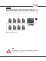
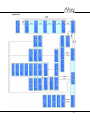
User manual
Abyzz Control System
1
© 2013 venotec GmbH
GmbH
Am Nordkreuz 36
26180 Rastede
Deutschland
www.venotec.de
The product specifications may deviate from the information in this manual due to
technical improvements and innovations. Abyzz and venotec are registered
trademarks.
Valid as of: 25.10.13
2
Table of content
Page
Table of content
3
Table of figures
4
Preface
5
Scope of delivery
6
Function description
7
Warnings
8
Installation
9
Overview of possible flow pattern simulations (examples)
11
Brief description of the control elements
19
General information about operation
20
Commissioning
21
Feeding break
22
The hardware menu (Setup Hardware)
23
The profile programming (Setup Profile)
24
The special functions menu (Special Functions)
29
Detailed display
30
Service mode
31
Guarantee
32
Troubleshooting
33
Disposal
34
Directory of keywords
35
Appendix
36
3
Table of figures
4
Page
Fig. 1
System overview
9
Fig. 2
Flow profile (example)
25
Fig. 3
Programming example
26
Preface
Thank you for buying venotec’s Abyzz Control System (ACS). This powerful
product allows you to optimally control multiple, currently up to eight, suitable
Abyzz pumps. This manual aims to help you start using the product and make the
required settings.
In order to reap the benefits of the device for as long as possible, please read the
operating manual carefully and observe our recommendations.
The high level of complexity of the setting options requires careful familiarisation
with the system in order to make the required settings. This manual contains
programming tips in order to help you set the device according to your
requirement.
The materials used have been rated for a long service life and meet the most
stringent requirements and quality standards. All parts used are supplied by
German suppliers and are manufactured in Germany according to the highest
quality standards. Thus, they deserve this label:
“Made in Germany”
Should the quality of your product not meet your expectations, please contact the
dealer who sold you the product or contact us directly. We recommend that you
use the provided form to register your product with us so that we can provide you
with the best possible service. Please make sure that the serial number on the
product remains legible and be ready to provide us with this number if asked.
Legend
This symbol indicates particularly important information.
5
Scope of delivery
1* Abyzz Control System (ACS)
1* 5m light sensor
1* operating manual
6
Function description
You can use the ACS to set separate, permanent flow rates or create random flow
patterns or complex wave profiles for every connected pump. Various monitoring
functions and an alarm system are also at your disposal. Moreover, you can
generate different fountains in the pond or the garden.
The ACS furthermore informs you about the required maintenance intervals as
well as current consumption and allows you to connect external alarm systems to
your system. The device is suitable to be used with electronically controlled Abyzz
pumps. You can smoothly operate different suitable pump models at the same time
on one ACS.
The communication takes place through a serial connection with the connected
devices; it is generated using a 9-pole cable. The ACS software assigns a onetime address (number 1 to 8) to the pumps within the scope of the commissioning.
This address remains saved in the pumps and can also be deleted or changed
through the ACS.
During operations, you can query operating data such as driver temperature, ID
data, current consumption or current speed of your pumps. If there is a fault (e.g.
dry run or pump blockage), the ACS triggers an alarm signal and informs you of
the problem.
In the night mode, the flow powers can be automatically reduced in order to save
energy and to reduce sound and stress (in the random mode, the set maximum
value is automatically reduced by 50%).
A feeding break (3 min.) can be switched on any time in order to remove the feed
sucked in by the filter. During the feeding pause, all connected pumps rotate with a
power of 5% in order to prevent animals from entering the pump channel.
You can also make all pumps run in the wave profile with minimum power in order
to keep animals away from exhaust openings (fish protection function). We
recommend a minimum power of 5% instead of a pump standstill in case of free
programming.
For more details, please refer to the respective chapters.
7
Warnings
8
-
You must disconnect the mains plug before working on the pumps!
-
Do not disconnect the motor supply line from the driver at any time
during operations!
-
Only connect parts that clearly belong together!
-
Make sure that supply lines, connectors, and the driver are kept dry and
protect the components from damage.
-
Do not work on cabling or the driver if you have wet hands.
-
Do not use the product if any of the people in the vicinity are in the water
or if anyone is in contact with the water.
-
Check the product for damage before use. Never use a product that you
know is damaged.
-
Connect Abyzz devices only to suitable sockets that have earthing
contact, correspond to the applicable standards and are fused with a
residual current circuit breaker (FI).
Caution - high voltage: It is prohibited to expose the electronic
components of the product. This must only be done by the manufacturer!
Installation
The ACS should be installed in a position that is easily accessible for you. For a
surface installation, screw holes have been provided on the rear panel of the
housing. The mounting wall must be dry and protected from splashes of water and
damp. Please pay attention to the cable length; this should not be longer than 2m
from the ACS to the first driver to be activated. Please pay attention to the cable
length of the light sensor (5m). Suitable extensions are available at venotec. Refer
to figure 1 for an overview.
Figure 1: System overview
Note:
Flush installation is also possible; it should however be carried out
only by venotec or by persons authorised by venotec, since the
device must be opened for this.
9
Pump connection
The communication with the pumps takes place through the 9-pole sub-D socket
on the bottom of the housing. First connect the provided cable with the 9-pole
socket on the ACS.
Only then connect the Abyzz drivers. Read the manual completely before
connecting the pumps. Incorrect connection of the pumps can cause malfunctions.
Light sensor
Install the light sensor below the aquarium lighting with the sensor in the direction
of the light at a reasonably safe distance (at least 50cm in case of HQI lighting, at
least 20cm in case of T5 lighting) and connect the sensor to the contact provided
for the same on the ACS (3-pole plug adapter). You can later check in the
overview mode of the ACS whether the sensor detects the lighting phases
correctly and make changes in the installation if necessary.
Mains connection
The ACS is connected to a suitable socket using the mains cable. The device
requires a voltage of 230V/50Hz (a country variant with 115V/60Hz is also
available).
Caution:
The 9-pole plug is NOT suitable to be connected to a computer.
Incorrect connection to external devices will damage the product
and render the guarantee invalid.
10
Overview of possible flow pattern simulations (examples)
The following examples should serve as suggestions and only show selected
possible operating modes and uses. If a single controllable pump has already
been connected, you can still enable the following flow pattern simulations:
1. Continuous flow (PERMANENT)
The set power of 0…100% is maintained, the pump runs continuously.
This mode is suitable e.g. for feed pumps.
2. Wave effect (WAVE)
The pump capacity can be varied between two powers; the times and
powers can be selected freely (0…100%, 0…480s or 0…480min).
3. Tidal simulation (TIDE)
The pump capacity can be varied between two powers; the times
automatically correspond to the average tidal time (6 hours, 15
minutes) of the earth.
11
4. Random flow (RANDOM)
The connected pump is activated randomly in terms of power and time
and thus generates a random flow situation in the pond. In this case,
only the maximum and minimum pump power is programmed.
We recommend operating the pumps manually with full
power before activating the random mode in order to
ensure that water does not get out of the pond. We
explicitly point out the danger of higher waves that
could be generated due to random flows.
5. Freely selectable flow profile (WAVE)
You can programme a free profile, in which you can set power and
section duration in four repeating sections.
6. Night reduction (NIGHT MODE)
The power of the pumps can be changed automatically (in the random
mode) or in a freely programmable manner for individual pumps
(stress reduction for your fosterlings, sound reduction, reduction of
energy consumption).
12
If you can connect multiple pumps, you can generate more flow
variants besides all aforementioned settings:
7. Pump sequence control
You can programme any sequences with the freely programmable
profiles in order to generate stronger flows by combining multiple
pumps.
13
8. Alternating flow direction
Depending on the arrangement of the outlets in the tank or pond, you
can use customer-specific programming to generate alternating flows
from different directions.
14
9. Freely selectable flow profile with rotation
The freely programmable profiles can be created such that they rotate
among themselves in their phases (sequence). With this, you can
create interesting effects (addition and subtraction of waves). Here too,
there is the danger of generating waves higher than those possible
with normal pump power.
15
10. Combinations of different programmes
All combinations from the aforementioned examples can be used
together.
16
11. Feeding break
When starting a feeding break, all connected pumps run with a 5%
power independent from their programming. After the abort or end of
the feeding break (180s), all pumps restart with their normal
programming.
17
12. Change of profiles
You can change between different profiles according to the light sensor
or a set time, e.g. programme a wave mode during the day and a quiet
continuous mode at night.
Day:
Night:
18
Brief description of the control elements
Display:
The display serves for the display of operating data, programmes and messages
of the ACS. The display switches off after some time if no button has been pressed
(screensaver to increase the service life). Briefly press any button to reactivate the
display.
LEDs:
The three light emitting diodes indicate different information:
-
Power:
Flashes every second as soon as a pump has been connected correctly
and indicates correct communication.
-
Service:
Indicates when the ACS is in the service mode, i.e. either for pump
cleaning or for the reminder of a due maintenance interval.
-
Alarm:
Lights up when a fault is detected.
Keypad:
The user operates the ACS using the buttons. The buttons [⇨] and [⇦] navigate in
the menu structure, [+] and [–] serve for setting operating values, [Pause] starts or
ends a feeding break. From every submenu, you can go to the next higher menu
by pressing the button [Menu]. The button [Mode] changes from the overview
mode into the detailed mode or changes operating modes in the programming
mode. [Menu] calls up the programming menu, [Enter] confirms inputs, saves
settings or starts processes.
Please refer to the appendix for an overview of the menu structure and of the
navigation therein.
Remark:
During the programming, there can be brief interruptions in the communication
(buttons respond with a delay). This is normal, because the processing of flow
simulation in real time has a higher priority than the input of values. Correct inputs
are acknowledged with a beep.
19
General information about operation
The ACS is operated through a menu-based user interface. The menu structure is
graphically illustrated in the appendix.
The first display after switching on is the overview mode, with which the ACS
reports after every restart. On pressing the [Menu] button (several times), you go
to this mode if you were in a submenu before.
The second display option is the detailed mode: Specific information about the
connected pumps can be called up here. You can go to this mode by pressing the
[Mode] button in the overview mode.
You can go to the programming overview by pressing the [Menu] button in the
overview mode: Here, you can select whether you want to add and set hardware
(pumps) or use special functions.
You can go to the manual mode by pressing the [Enter] button in the overview
mode. Here, you can control or stop all pumps manually independent from the
already made programme settings. This is useful especially for maintenance and
testing purposes.
You can see the menu structure with the help of the overview plan. Generally: with
the [Menu] button within a submenu, you always go back stepwise to the overview.
Within the overview screen, the [Pause] button results in a pump standstill; when
the button is pressed once more, the pause is aborted and the profiles are
restarted. The buttons [⇨] and [⇦] navigate within the menu structure, the button
[Enter] confirms inputs, saves automatically or selects submenus.
After a power failure, the ACS automatically restarts with its saved data and goes
to the overview display.
20
Commissioning
Before the commissioning, make sure that no pump is connected. New pumps
must be integrated into the system individually one after the other; already
programmed pumps can remain in operation. Now plug the ACS into a suitable
socket. The device starts with a welcome message and goes into the overview
mode.
In the overview mode, all connected pumps are displayed in a brief overview
(display line at the bottom). If no pump is connected, then the display shows “None
programmed!”.
The line at the top changes continuously and displays status information.
Proceed as below in order to connect a new pump:
1. Connect the provided 9-pole cable with the ACS. Switch on the new
pump and connect the cable from the ACS to the socket on the pump
driver labelled as “Master”. If this pump does not have an address as
yet (this is shown in the display near the drivers), it is found
automatically.
2. Use the buttons [+] and [-] to enter the desired address to be assigned
to the pump (e.g. 1) and press [Enter]. If the storage location (address)
selected by you is already assigned, then the ACS reports this with the
note “used”.
After the automatic saving, you automatically go back into the
overview mode: the line at the top again changes automatically.
If you want to register more pumps, repeat this procedure.
If the linking does not function, e.g. because the driver already has an address,
you can also select the “Reset Slaves” function in the menu. In this case, all
connected driver addresses are deleted and the drivers can be added anew.
If you want to add already addressed pumps, simply select the “Search Slaves”
function in the hardware menu.
When you have assigned an address to your pump and are again in the overview,
you can start with the programming.
Tip:
Mark the pumps with the assigned addresses; this simplifies the subsequent
profile programming for you!
21
Feeding break
In order to execute a feeding break (180 seconds of “standstill” of all pumps),
press the [Pause] button in the overview mode; the display changes to “Feeding
break”.
The time of the break is counted backwards; after the time expires, the profiles are
restarted and the normal operation is taken up.
If you want to end the break early, press the [Pause] button once more.
During a feeding break, the pumps are not at a complete standstill, but run with a
low power of 5% in order to prevent animals from entering the pumps.
Thanks to a feeding break, the animals get longer time to eat before the feed is
rinsed in the filter system. With this function, you can reduce the water load and
the feed consumption.
Tip:
Use the feeding break each time when feeding in order to keep the water load as
low as possible.
22
The hardware menu (Setup Hardware)
All hardware settings can be made in this menu, i.e. pump setup.
-
Searching pumps (Search Slaves)
Newly connected pumps or even pumps that have already been
assigned with an address can be searched here.
If there are multiple pumps at the bus with the same address, this results
in communication errors. In this case, you must remove double drivers.
If you are not sure, reset all pumps at the bus (refer to the next point).
-
Resetting pumps (Reset Slaves)
All pumps existing at the communication connection are reset into the
delivery state irrespective of the address.
After this step, it is necessary to disconnect the individual drivers from
the power supply network and wait until all LEDs on the driver go out.
The drivers are then reactivated and can again be added to the system
individually as new devices.
-
Removing pumps (Delete Pump)
The selected pump is deleted; i.e. the management by the ACS is
ended. The saved address is also deleted from the driver so that the
driver is detected as a new device during a new setup.
23
The profile programming (Setup Profile)
In this screen, you select the pump to be programmed using the buttons [+] and [-]
and then press [Enter] to start the setup.
Now, you can first select whether the pump should run with changing profiles. You
can choose from:
- no – No profile change
The profile defined below is used continuously.
- by light – Profile change according to the lighting
Two different profiles are programmed below, which are activated according
to the lighting.
- by hours – Profile change according to the time
A change time of 1...48 hours and two different profiles are programmed
below, which are activated as per the expiry of the set change time.
You have the following setting options:
- Wave – Manual wave profile
Freely programmable flow profiles, which can be set separately for every
individual pump. In order to set such a profile, you must separately enter the
power of all four profile sections, the durations of the individual profile
sections and the powers in the night mode.
- Permanent – Permanent speed
A pump in this mode always runs at one speed. You must specify the
desired power for the operation during day and night.
- Tide – Tide simulation
A pump in this mode changes between two adjustable speeds every few
hours.
- Random – Random flow patterns
In this mode, the pump’s power is changed randomly at random times. You
must enter the desired minimum and maximum values only once. All pumps
set in this manner are controlled independent from each other.
At night, the maximum power is automatically reduced to half of the
maximum value during the day.
24
Depending on which operating mode you select for the respective pump, you are
automatically guided through the inputs in the next steps. All changes have direct
effects on the pumps so that you can observe the change directly. After you have
finished making the inputs, these are saved automatically.
Programming a wave profile
Figure 2: Flow profile (example)
Before programming your own profile, use the sketches on page 27 and 28 as
programming aid. Before programming, sketch as to how the individual pumps
should be controlled; this simplifies the programming for you.
Navigate to profile programming and select WAVE. Input options for speeds of the
profile sections 1&2 (Wave speed phase) and sections 3&4, profile section times
1&2 and 3&4, speeds for sections 1&2 and 3&4 at night (Wave @n.speed) are
displayed according to the sequence.
Change the values as desired; the connected pump responds accordingly. When
you are satisfied with the values, press [Enter] and you are directed to the next
input mask.
After the programming, leave the menu using the [Enter] button; the programme
setting is saved automatically.
Note:
During the programming, the wave simulation might no longer run synchronously
in case of multiple connected pumps, since you change the times during the
programming mode. This is absolutely normal – as soon as the values are saved,
the profiles are restarted and run synchronously.
25
As programming aid, you can sketch your own profiles on the following pages.
Enter the desired power in percent in the boxes at the top, the desired section
length in seconds at the bottom and the number of the pump in the leftmost box.
You can then simply transfer the values into the profile programming by comparing
your sketches with the figure.
Figure 3: Programming example
26
Programming aid:
27
28
The Special Functions menu (Special functions)
Special functions of the ACS can be used in the programming menu under
“Special function”.
-
External alarm (Ext. alarm)
The ACS has an external alarm output within the scope of an isolated
alarm contact (N/O and N/C). Using this contact, you can activate
external alarm systems. This must be connected by venotec or qualified
personnel. The contact takes place through the 3-pole terminal block in
the ACS, which is marked with S, M and O. M is the centre contact of
the relay; S and O refer to N/O and N/C contact.
The relay is normally drawn up and drops in the event of an alarm if you
have activated the external alarm in the menu.
-
ACS version query (ACS HW, SW)
In this display, you can read out the hard- and software version of the
ACS.
-
Generating delivered state (Total reset ACS)
By pressing [Menu], [+] and [-] at the same time, you can reset all ACS
settings that have been made; the device is now again in the delivered
state and can be re-programmed.
-
Operating hours counter (Operating hours)
The ACS has an integrated operating hours counter, which works
continuously and cannot be reset.
-
Timer mode (Timer mode)
In order to programme longer flow intervals, you can set the timer
functions on minute basis.
29
Detailed display
Press [Mode] in the overview mode to go to the detailed display mode. Here, you
can use the [Mode] button to navigate through the different displays and select the
pump to be queried using the buttons [+] and [-]. The following displays are
available:
-
Pump type
Here, you can query the hardware version number and the pump type.
-
Firmware version
The firmware version of the selected driver is displayed here.
-
Speed
The current motor speed (in revolutions per minute) as well as the power
requirement of the ACS (in %) is displayed in this display.
-
Temperature driver
This screen shows the current temperature of the driver in degrees
Celsius. In case of a temperature of over 60°C, the device should be
cooled; if necessary, a different installation location should be selected.
-
Power consumption
The current power consumption of the selected driver is displayed here.
The accuracy is ≤10%.
You can go back to the overview by pressing [Mode] once more.
30
Service mode
The ACS continuously monitors the operating state of all connected pumps. If a
device fails, you are informed about this and an alarm signal can be heard. If you
switch off a pump for maintenance and cleaning, the ACS will detect a fault, trigger
an alarm and request for acknowledgement:
If you do not confirm the alarm as a service intervention carried out by you, the
alarm state is retained until the cause of the fault is rectified.
If you acknowledge the alarm with the [Pause] button, the ACS goes into the
service mode and ignores all further error messages for a period of 30 minutes.
This is displayed in the overview mode. In this case, the maintenance counter is
also set to zero. After the correct operating state is restored by again switching on
and correctly connecting the previously disconnected pump, the ACS detects the
pump automatically and leaves the service mode.
After 30 minutes, the ACS will trigger a new alarm. If the maintenance work is not
complete at this time, you can acknowledge again. In this manner, the system
ensures that you do not forget to switch on a pump again.
Alternatively, you can deregister the pump from the ACS for a longer disconnection
of the pump. In this case however, you need to set up the pump again.
If a connected device is disconnected e.g. due to an interruption of the connection,
this can result in a delayed keypad response, since the ACS continuously
searches for the missing device. This is normal.
Maintenance counter
Approximately every three months, the ACS will remind you to clean the pumps
and carry out maintenance work by lighting up the yellow Service LED. This state
is retained until the service mode is activated.
31
Guarantee
In accordance with the implied warranty, we provide you a 12-month guarantee.
You can also extend the product guarantee period from 12 months to 10 years
within 4 weeks of purchasing the product (date of invoice) after registering your
product successfully. For more details, see the provided device registration and
guarantee extension form.
If you have a complaint, please contact us directly and if necessary, send the
device back in its original packaging wherever possible and with proof of purchase
and guarantee directly to venotec. Please note that we cannot accept non-prepaid
deliveries. Such deliveries will be sent back without being processed. The
guarantee covers material, functional and production faults that can occur when
using the product as intended. It expressly does not cover wear and tear and
transport damage, claims for compensation above and beyond compensation for
the product itself, or damage resulting from improper use, negligence, incorrect
installation, or interventions and changes carried out by unauthorised persons. We
expressly exclude such scenarios from our scope of liability. Any secondary
damages such as the loss of coral, fish, or water damage caused by pump failure
or a lack of intake protection are expressly excluded from guarantee and warranty
claims. Calcination inside the pump and any resulting damage and/or motor
damage, damage due to improper use as well as any damage to cables (e.g.
chafed cables) are expressly excluded from the guarantee. The guarantee is
invalidated in the following cases: Removed original plugs, use of non-original
spare parts or modifications, impeller wheel damage resulting from parts sucked
into the pump, motor damage caused by the tapering of the intake port or if the
pump is operated with a completely or partially closed ball valve in the intake area,
motor damage caused by persistent dry running, limescale damage resulting from
the improper use of chemicals or the use of unsuitable chemicals, motor damage
resulting from upstream external electronic components and damage resulting
from damp in the driver.
Technical changes
Due to the constant further development of our products and innovations that, in
particular, serve to improve quality, safety, and technical progress, venotec
reserves the right to make technical changes.
This manual is applicable for all devices with the software version V2.3.1. In case
of a software modification, we will provide corresponding documents.
32
Troubleshooting
In case of a malfunction, the ACS will display an error message and sometimes
trigger an alarm. If the communication between the pump and the ACS is
interrupted, although the pump is still working, the pump will change to the power
set on the driver. This offers more safety, since an adjustable pump power is
guaranteed even if the communication line is interrupted.
In case of a malfunction, please act according to the following table:
Malfunction
Cause
Remedy
Pump is not found a) Connecting cable is
a) Check connecting cable
(during installation) defective / not connected
b) Check power cable of the
b) Driver without operating
driver
voltage
c) Connect only one new
c) Several new drivers
driver to the device at a time
connected at the same time
Pump is not
a) Driver is already addressed a) Use the already assigned
detected as new
address, or reset driver to
device
delivered state (refer to page
23)
Err #01 or T
a) Bus system line break
a) Check bus system
b) Driver power failure
b) Check voltage supply of the
driver
Err #02 or C
a) Connecting cable
a) Check connecting cable,
defective / damaged
check plug
(corrosion)
b) Reset all connected
b) Multiple drivers at the bus devices and add them anew to
with the same address
the system
Err #03
a) Connecting cable
a) Check connecting cables
defective / damaged
Err #04
a) Driver error
a) Disconnect drivers from the
ACS and check individually.
Possible causes are blockage
of a pump, excess
temperature protection,
defective motor cable
33
Disposal
As per the directive RL2002/96/EC, this product cannot be disposed of in normal
household rubbish.
Within Germany, our customers can send old devices back to us free of charge for
proper recycling or disposal. The WEEE number for reporting to the EAR
(Germany registry of old electrical equipment) is:
DE 16546900
If you do not want to dispose of the product through us, you must bear the costs of
disposing of the product in accordance with legal requirements. In doing so, you
release us from our obligations as per Section 10 Paragraph 2 of the ElektroG
(Electrical and Electronic Equipment Act) and absolve us from all upcoming claims
from third parties.
CE declaration of conformity
The manufacturer
venotec GmbH
Am Nordkreuz 36
26180 Rastede / Germany
hereby declares that the design of the control unit
Abyzz Control System (ACS)
complies with the following specifications:
EC EMC Directive (89/336/EEC and 93/97/EEC)
Applied harmonised standards:
DIN EN 61000-6-1 (resistance to interference);
DIN EN 61000-6-3 (interference voltage, interference field strength);
DIN EN 61000-3-2 (harmonics);
DIN EN 61000-3-3 (flicker);
DIN EN 61000-4-11 (voltage drops);
DIN EN 61000-4-4 (burst);
DIN EN 61000-4-2 (ESD);
DIN EN 61000-4-5 (surge)
DIN EN 61000-4-5 (Surge)
34
Directory of keywords
A
List of figures 5
Address 8, 32
Connections 11
Appendix 53 et. seq.
Delivered state 43
I
B
Control elements 22
Operation 30
Example 39
Operating hours
counter 44
K
C
CE declaration of
conformity 57
D
Display 22
Speed 45
E
Extension 12
Disposal 56
External alarm 43
F
FAQ 54
Feeding break →
Futterpause
Error codes 52
Firmware 45
Fish protection
function 9 Functional
description 8
Feeding break 8, 33
G
Guarantee 49
Exclusion from
guarantee 49
H
Hardware setup 34
Commissioning 31
Installation 10
J
L
LEDs 23
Power consumption
46
Light sensor 12
Scope of delivery 7
S
Quick guide 25
Service 23
… mode 47
Flow simulation 14
et. seq.
Flow profile 35
Special functions 43
Troubleshooting 50
T
Buttons 24
Temperature 46
Technical changes
49
Timer mode 44
M
Master 11
Minimum power 9
U
Flush installation 10
Overview 10, 55
N
Night reduction 16
Mains connection 12
V
Version 43, 45
Preface 6
O
W
Wave →
Wave mode 35
Maintenance
counter 48
P
Permanent 35
Pump 8
… connection 11
… search 32
… reset 34
… deletion 34
… type 45
Profiles 35
Profile programming
35 et. seq.
Programming aid 41
X
Y
Z
Random mode 36
Appendix
Q
R
Random →
Random mode
35
36
Appendix
37
38