1
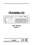
Manual
A16 MK-II
professional 16 channel AD/DA converter
FERROFISH
advanced audio applications
© Ferrofish GmbH
Version 1.1
Introduction
Introduction
Thank you very much for choosing to purchase this product.
The A16 MK-II can convert simultaneously, 16 audio channels
from digital to analogue (DA) and 16 audio channels from
analogue to digital (AD). You can use both, MADI and ADAT
as digital interfaces. Furthermore, you can also transmit signals
between these two interfaces.
The two TFT screens display the levels of all inputs and
outputs in high resolution.
The A16 MK-II combines high quality 'audiophile' conversion
characteristics with flexible routing / I/O that fits seamlessly
into your professional studio.
Software and Updates
For further information and current drivers and software please
visit our website: www.ferrofish.de
1
Operation
Operation
The A16 MK-II can be controlled via three front panel buttons
SAMPLE RATE, SYNCHRONIZATION and MENU.
Alternatively, you can use your PC to remote control the A16
MK-II using the MIDI interface.
In the main screen the frequency and synchronization can be
set using the corresponding buttons.
Pressing MENU opens the main menu, where you can
navigate with the SAMPLE RATE and
SYNCHRONIZATION functions.
Pressing MENU again will then confirm the selected function
choice.
main screen
The TFT main screen shows all 32 channels of the A16 MK-II
as well as the basic settings of sample rate and the input signal
from which the A16 MK-II takes it's timing. Additionally, it
displays the interfaces to which the analog inputs/outputs are
routed in the top right corner.
2
Digital Interfaces
Digital Interfaces
Every digital device requires a sampling rate for proper
operation. The A16 MK-II can either generate such sampling
rate itself (Master) or receive it from another device (Slave).
It is important that all devices within a digital domain work
with the same sampling rate. For that reason there has to be
exactly one master generating the sampling rate, while all other
devices have to refer to this sampling rate as a slave.
It is not possible to connect two master devices with
each other, even if set to the same sampling rate.
Because the units are not synchronized, even the
smallest variations of the sampling rate would cause
failures.
With the SYNCHRONIZATION button you can select
whether the device shall be master or slave to MADI, ADAT or
BNC.
If the corresponding field in the TFT is green, the
A16 MK-II found a valid sampling rate at the selected input.
In case you have set the A16 MK-II as MASTER, it will
generate the sampling rate. Now you can select the frequency
between 32kHz and 192kHz via SAMPLE RATE.
3
Digital Interfaces
The higher you set the sampling rate, the higher will
be the maximum frequency to be transmitted
digitally, as it corresponds exactly to half the value of
the sampling rate. However, the data volume will be
increased for higher sampling rates. For that reason
the number of channels halves in case of 88.2kHz or
more for MADI and ADAT, and for 192kHz the
channels are quartered.
If you set the A16 MK-II to ADAT, MADI or BNC, it will
display the measured sampling rate. Since it is not possible to
decide from the ADAT/MADI signal whether it works with
one of the higher sampling rates, you may select these via
SAMPLE RATE manually.
In the next step you decide which digital data to be converted
by the A16 MK-II. By long pressing MENU you choose from
five options:
Routing Presets
MADI 1: MADI 1-16
→ analog →
MADI 1-16
(+ ADAT)
MADI 2: MADI 17-32
→ analog →
MADI 17-32
(+ ADAT)
MADI 3: MADI 33-48
→ analog →
MADI 33-48
(+ ADAT)
MADI 4: MADI 49-64
→ analog →
MADI 49-64
(+ ADAT)
ADAT:
→ analog →
ADAT
(+ MADI 1-16)
ADAT
For example, if you select the first option, the A16 MK-II will
convert the first 16 MADI channels into analog and the analog
inputs will be sent to the first 16 MADI channels. All other
MADI channels will be passed through without any changes.
4
Digital Interfaces
Besides the five presets there are many more routing
possibilities. In order to configure these settings press
MENU and then select routing. Please refer to the
chapter Routing for further information.
MADI
MADI is a very popular audio interface offering 64 channels at
a maximum cable length of 2 kilometers!
Furthermore, when using more than one A16 MK-II, it is also
possible to daisy chain the MADI cable. In this case the
device's output will be connected to the next device's input.
Hence you can connect, for example, four A16 MK-II in a row
in order to use the maximum number of 64 MADI channels.
However, in case of higher frequencies the cable's bandwidth
is not sufficient for the maximum number of channels. The
following table gives an overview of the bandwith:
Frequency
MADI Channels
32kHz, 44,1kHz, 48kHz
64 (56) channels
88,2kHz, 96kHz
32 (28) channels
192kHz
16 (14) channels
An older MADI specification used only 56 channels instead of
the 64 channels being used today, giving the advantage, that a
higher variation of the sampling rate was permissible
5
Digital Interfaces
(+/-10%). Hence a signal with 53kHz still could be converted
(48kHz +10%). Nowadays most people don't need this
variation feature anymore and instead prefer to use all 64
channels.
If the A16 MK-II recognises only 56 channels at the
MADI input, the outputs will also be reduced to 56
channels. This function allows to use older devices
not capable to handle 64 channels.
MADI SMUX Modes
In case of frequencies higher than 48kHz, SMUX is used for
transmission. This means, that two (or four) channels will be
combined into one channel. For example, in case of 192kHz, a
48kHz MADI data stream (frame) will be generated. However,
four channels will be combined in order to achieve the higher
data volume. Since this 48kHz data stream can't be
differentiated from a “real” 48kHz signal, you can select it
manually by pressing the SAMPLE RATE button.
The frequencies 88.2kHz and 96kHz are a special case, since
there are two choices: Either SMUX can be used (two channels
combined each in a 44.1kHz or 48kHz data stream) or the
frequency is used directly, i.e. using an 88.2kHz (or 96kHz)
data stream. Both methods will have the same result. You can
adjust the desired mode in the main menu selecting the item
SMUX (48k frame or 96k frame).
Please note that all devices connected to the MADI cable need
to have the same frame size, as otherwise the signal won't be
recognised.
6
Digital Interfaces
Frequency
Grouping
Mode*
48kHz (32kHz, 44,1kHz)
no
48k frame
96kHz (88,2kHz)
no
96k frame
96kHz (88,2kHz)
2 channels each
48k frame
4 channels each
48k frame
192kHz
* only shown for 48kHz, 96kHz, 192kHz
ADAT
ADAT is probably the most common digital audio connection
used in multichannel interfaces. Since an ADAT cable can
transmit 8 channels only, the A16 MK-II has two pairs of this
interface.
Similar to MADI the number of available channels is only half
or only a quarter in case of higher frequencies:
Frequency
ADAT Channels
32kHz, 44,1kHz, 48kHz
2 x 8 channels
88,2kHz, 96kHz
2 x 4 channels
192kHz
2 x 2 channels
If you use ADAT for higher frequencies, the first 8 (or 4)
outputs will be used only. The remaining outputs will repeat
the signal of the first 8 (or 4) outputs. Only the first 8 (or 4)
channels will be used as analog inputs respectively.
As with MADI, set the desired mode using the SAMPLE
RATE button.
7
Digital Interfaces
WORDCLOCK
When using many devices which should run with the same
sample rate, it is a good idea to use the Wordclock (BNC)
connection of the A16 MK-II. It has both in and out
connections to synchronize timings between multiple devices.
The A16 MK-II can output a master wordclock, or accept (and
then throughput) a signal from other devices.
status screen
The status screen is a useful help when configuring the
A16 MK-II, giving an overview of the digital inputs. To
activate it, press MENU and then select status. The screen
shows for every digital input, whether it receives a valid signal
(signal) and whether this signal's sampling rate is correct
(lock). Only if both conditions are met, the A16 MK-II will use
the signal.
8
Analog Interface
Analog Interface
All analog in-/outputs are balanced and can be adjusted to
levels from -10dBu (“consumer”) to +4dBu (“professional”).
If you adjust the output, for example to +4dBu, you should set
the corresponding input to -4dBu in order to balance the
amplification one by one.
In doing so you can adjust the level of each channel
individually.
The settings are chosen in a way that, in case of analog full
scale, a headroom of 6dB remains to avoid any digital clipping.
Hence you can amplify the inputs by max. 6dB
without the converters of the A16 MK-II distorting
the signal. Accordingly the output signal will be on
full scale if the digital signal is still below 6dB.
The following table shows the common standard levels and the
corresponding level adjustment of the A16 MK-II:
Setting
Application
+4dBu (+6dBu)
Professional level with 6dB headroom
-2dBu (+6dBu)
Professional level without headroom
-10dBu (+6dBu)
Consumer level with 6dB headroom
9
Analog Interface
Level and gain screen
All analog levels and gains can be adjusted independent of
each other in steps of 0.5dB. Please press MENU and then
select level or gain.
Now you see a fader for each of the 16 channels (depending on
the selection either the input channels or the output channels).
In the first step you select those faders you want to move. You
may select various groups of faders or individual faders.
Next, press MENU in order to move the selected faders. In the
top right corner of the window you can see the current level of
each fader.
Press and hold MENU to leave the settings menu.
10
Routing
Routing
Press the MENU button and then select routing in order to
adjust the routing between the digital channels and the analog
input/output channels.
You can now route the analog inputs to a MADI group of 16
outputs and also the ADAT inputs to a MADI output group.
After pressing MENU you can adjust another routing for
88,2kHz/96kHz and then one for 192kHz.
After pressing MENU again, the display switches to the output
routing. Here you can choose what you want to set on the
analog output channels and the ADAT outputs.
Press and hold MENU in order to leave the routing menu.
All MADI groups that were not assigned in the
routing will be passed through from the MADI input
to the MADI output. This makes it possible to daisy
chain multiple A16 MK-II.
As an alternative to the procedures described before
you can also select one of the five routing presets. To
do this, press and hold MENU, and then select the
desired preset.
11
Routing
The following table shows an overview of possible routings.
MADI 1 are the first 16 channels, accordingly for MADI 2 to
MADI 4.
analog
ADAT
MADI 1
MADI 2
MADI 3
MADI 4
destination
source
analog
X
O
O
O
O
O
ADAT
O
X
O
O
O
O
MADI 1
O
O
MADI 2
O
O
MADI 3
O
O
MADI 4
O
O
MADI will be
routed through
if not assigned
otherwise
Example 1: 64 x in, 64 x out with four A16 MK-II
In this example four A16 MK-II are simply chained in row in
order to have 2 x 64 channels. For this purpose, set the four
A16 MK-II from MADI 1 to MADI 4 in the routing preset.
12
Routing
Example 2: 64 x in, 64 x out with two A16 MKII and two A16 ultra:
If you own two ADAT converters (in this example the
A16 ultra by Sonic Core), you can incorporate them as shown.
In doing so, set the routing for the two A16 MK-II as follows:
Device
Routing
#1 analog
MADI 1-16
#1 ADAT (#2 A16 ultra)
MADI 17-32
#3 analog
MADI 33-48
#3 ADAT (#4 A16 ultra)
MADI 49-64
13
PC remote control software
PC remote control software
The PC Remote Control Software A16remote.exe lets you
control and monitor all your A16 MK-II from your PC. All you
need to do is connecting the devices to your PC via MIDI.
Alternatively, you can also use the MIDI signal embedded into
MADI. In this case you will need a MADI card supporting this
function. Please refer to the manual of the card's manufacturer
for further information.
After starting the program select the MIDI interface to which
the A16 MK-II is connected. Then press connect. All devices
connected to MIDI will now be recognised and displayed in
the list.
After selecting the desired A16 MK-II you can control it by the
program's functions.
If you are going to use the MIDI signal embedded
into MADI, transmission of the MIDI signal will be
stopped in case of a loss of the MADI signal. For that
reason the functions synchronization and sample rate
are deactivated by default. If you want to use these
functions, please select the menu item enable
extended functions.
14
PC logo upload software
PC logo upload software
You can equip the A16 MK-II with your own logo that will be
displayed upon switching on and when activating the menu.
Additionally, you can enter a name with up to 16 characters
which will be transmitted to all PC programs for identifying
the A16 MK-II.
After starting the software A16logo.exe you have to establish
the MIDI connection at first. Select the interface and then click
connect.
Now you can select the desired A16 MK-II the logo shall be
applied to.
You can load a JPG, BMP or an image in another common
graphics format using the function file control. The image will
be scaled to the screen size of the A16 MK-II automatically
(220 x 176 pixel). You can additionally assign a name to the
A16 MK-II.
The function send will store the image, together with the name
of the A16 MK-II, permanently in the device.
It may happen that the image doesn't fit into the
memory of the A16 MK-II due to the image size. In
such a case change the image in a way that it features
many single-coloured regions, as the compression
rate is higher then.
15
CE / FCC Compliance
CE / FCC Compliance
This device complies with the limits of the European Council
Directive on the approximation of the laws of the member states
relating to electromagnetic compatibility (RL89/336/EWG,
RL73/23/EWG).
This device complies with the limits for a Class B digital device,
pursuant to Part 15 of the FCC rules.
RohS
This device has been soldered lead free and fulfills the
requirements of the RohS directive.
Information about Disposal
According to the Directive on Waste Electrical and
Electronic Equipment – RL for electrical and
electronical devices ) RL2002/96/EG this device has
to be reused or recycled after its usage.
16
Warranty
Warranty
Each A16 MK-II is tested by us and all functions are checked extensively. Only
high quality components are used, which enables us to give two years full
warranty. As confirmation for the purchase date please keep the sales receipt.
In case of a defect please consult your dealer. Defects, which are caused by
improper installation or use are not subject to the warranty. In this case the
repair is with costs.
Compensation in any kind, i.e. of secondary damages is excluded. Any liability
beyond the merchandise value of the A16 MK-II is excluded. General terms and
conditions of Ferrofish GmbH apply.
Disclaimer
This documentation describes the actual state of development. Ferrofish does
not grant any warranty, neither explicit nor implicit, for the correctness of this
documentation. I.e. Ferrofish isn't be liable for loss of data in assiciation with
this product or this documentation. In particular Ferrofish is not liable for
consequential damage, which are result from using the product or
documentation.
This document may use trade names or product names of other companies, these
are subject to legal regulations, and are owned by the property holders
accordingly. This is also true, even if it's not stated in the text explicitely.
This product and documentation are subject to the current terms and conditions
of the Ferrofish GmbH.
17
FERROFISH
advanced audio applications
[email protected]
www.ferrofish.de