1
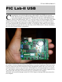
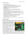
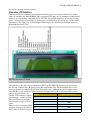
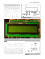
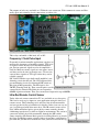
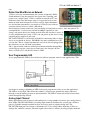
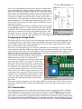
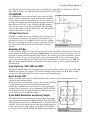
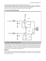
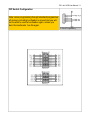
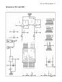
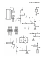
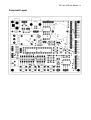
Microtronics Pakistan
PIC Lab-II USB User Manual / 1
Invent Future
PIC Lab-II USB
User Manual
Amer Iqbal Qureshi
www.electronicspk.com
[email protected]
PIC Lab-II USB User Manual / 2
PIC Lab-II USB
C
ongratulations on purchasing Microtronics Pakistan PIC Lab-II USB development
board. This board can act as both development as well as trainer to help you learn and
explore Microchip PIC Microcontrollers. The PIC Lab-II features PIC18F2550 microcontroller from Microchip®. This is a 28 pin mid range 8 bit microcontroller with 32KB
flash program memory. The special feature of this controller is that it has built in USB 2.0 slave
module, so you can learn and explore how to make USB compliant devices. Another special feature of this and other PIC microcontrollers is ability to self program. This ability has been utilized
by some developers to upload the new .hex file using serial or USB interface, thereby eliminating
the need of an external hardware programmer.
PIC Lab-II USB has many commonly used peripheral devices pre-fabricated so that you can learn
to use them, as well as incorporate them in your project as per your requirement. The devices have
been pre connected to the microcontroller IO Lines through DIP switches that can be used to connect or disconnect a device as per your needs. All IO lines have also been brought out as standard
0.1” male jumpers grouped together as microcontroller Ports along with 5V power supply for easy
connections with your project circuit that needs to be controlled by the controller.
The board can be powered through external 9-12V DC adapter or through USB connection of the
host computer.
PIC Lab-II USB User Manual / 3
Features In a Glance
•
•
•
•
•
•
•
•
•
•
•
•
•
•
•
•
•
•
•
•
•
•
•
PIC18F2550 Microcontroller
Supports other 28 Pin Microchip PIC Microcontrollers
Character LCD interface (All HD44780 compliant standard LCDs Supported)
USB Type-B connector (implements USB 2.0 Slave features with 18F2550)
I2C EEPROM (All 24CXXX Chips are supported) 24C08 included
I2C Real time clock with battery backup (DS1307 included)
One SPDT 10A relay
38KHz IR Remote sensor
Dallas One-Wire device connectivity (DS18B20 digital temperature sensor)
One channel ADC with voltage divider and 5.1v zener protection circuit
Three tactile push switches
Rest switch (can be used as tactile switch with proper configuration settings for MCLR)
Two channels of PWM with Low-Pass filter and OP-AMP current booster.
A Pre-Amp to acquire low power frequency input to measure external signal frequencies
Standard In Circuit Programming header as per Microchip standard for use with PICkit-2
One user programmable LED
20 MHz Crystal Oscillator (18F2550 can be configured to run at 48MHz on the same crystal)
On-board 5V 1A power supply regulator for external DC adapter (9-12V)
Selection jumper to select power supply source, external adapter or USB
All IO lines available as 0.1” headers for easy expansion.
Standard FR4 double sided PCB with plated through-holes
Dimensions : 3 x 4 inches
All Devices can be connected or disconnected to microcontroller lines via Dip switches
Powering The Board
The board can be powered through an external 9-12V DC supply or through USB host computer.
Most of the times when developing an application it is more convenient and practical to power the
board through USB. However remember the capacity of USB to supply current is limited. The requirements of board itself including LCD is not
much and can be provided by USB safely. However
in
case you also want to power the external device
through this board like motors, or an array of bright
LEDs it will be better to use external power supply.
In
that case you will still be able to program over USB.
Close to the USB connector there is a jumper with
three headers. This selects the supply source, between external or USB. A red LED in power section
shows the status of supply.
The external power supply will also be useful in
cases where after programming the board is supposed to run without computer, as a standalone device. The power supply is also available for expansion cards etc through the IO headers. Make sure the Power supply Select Jumper
power supply from IO headers is used only to supply
the
power and not to get power from other boards.
Two devices, namely Relay and LM358 operational amplifier do not get power from 5V source,
indeed they get 9-12V supply from the external source. Thus relay can not be turned ON from
USB supply. Similarly DAC signals can not be produced from USB power supply. More details on
PIC Lab-II USB User Manual / 4
this will be given in relevant sections.
Character LCD Interface
Character LCDs are commonly used in microcontroller projects to interact with user or display
values of variables etc. Hitachi HD44780 is a popular LCD that is used. A number of other manufacturers are also making compatible LCDs. The PIC Lab-II USB board has an interface for this
device. A female type header with 16 connections is available that will accept the standard LCD.
The interface has supply for LCD backlight. Following are the standard pin configurations of
HD44780 character LCDs.
HD44780 Character LCD Pinout
The LCD has 8 data lines and 3 control lines. PIC Lab-II USB LCD interface uses 4 data lines
D4..D7 and 2 control lines, Register Select (RS) and Enable (En). The Read/Write line is connected to ground to configure the LCD in Write mode only. Although header has 16 pins, data
lines D0..D3 are nor connected. Thus the board configures the LCD in 4 bit mode. The connections to microcontroller are:
LCD Pin
Microcontroller Port
Usually LCD contrast is adjustRB2
able through a variable resistor. Register Select (RS)
This board however provides a Enable
RB3
fixed contrast using a 1.5K re- D4
RB4
sistor.
RB5
There is also no associated DIP D5
switch to connect or disconnect D6
RB6
the IO lines. If LCD is inserted D7
RB7
PIC Lab-II USB User Manual / 5
the lines get connected, and if you want to
use these IO lines through headers for some
other purpose you can remove the LCD.
The connector is general type and can accept
all LCDs that have pin connections and controller compatible with HD44780 LCD controller.
You can get various models of LCD with different display characteristics. Commonly
available ones are:
8x1 : 8 characters and one line
16 X 2 : 16 characters per line, 2 Lines
16 X 4 : 16 characters per line, 4 lines
20 X 4 : 20 characters per line, 4 lines.
LCD Schematic Connections
LCD Inserted into The LCD Interface Header.
Relay
Relay is required in microcontroller applications where
you want to switch a heavy AC or DC load through microcontroller. PIC Lab-II USB has a standard 12V relay.
It is powered through external DC adapter. Therefore
you can not use it when board is being powered through
USB.
The relay is connected through DIP switch to RA5 of
microcontroller. The relay is powered on through an
NPN transistor, which does not isolate it from the microcontroller, therefore beware when using with AC
load. For a serious application better get a spate module
with relays optically isolated from microcontroller.
Relay Circuit
PIC Lab-II USB User Manual / 6
The outputs of relay are available as a T-Block screw connector. With common in center and Normally open and normally closed connections on either side.
Relay Module with T-Block Screw Terminal
This relay can handle a 10A load, AC or DC.
Frequency / Clock Pulse Input
Frequently in microcontroller applications you have to
measure the frequency of incoming signals. TTL level
of signals can be directly fed to the microcontroller
pin, but low powered signals need to be amplified a
little bit. Moreover many signals are not square waves
and they tend to be sine or triangle wave. We need to
convert those signals to TTL type before they can be
reliably counted.
PIC Lab-II USB has a pre-built small amplifier / conditioning circuit for this job. The CLK output of this
preconditioning circuit is fed through DIP switch to
RA4 pin of Microcontroller. The RA4 pin is also
T0CKI (Timer0 Clock In). Thus external pulses can be Frequency Input Circuit
counted by the Timer0. The RA4 pin can respond to
60MHz signals maximum. Thus you can measure frequencies up to 60MHz.
Infra-Red Remote Control Sensor
Today infra-red remote controls for TV are available at very low price.
This can be used to give inputs to your application using the infra-red
remote sensor. This technology uses only one line of microcontroller
and you get the facility of a number of switches. Indeed you can say we
get a serial keypad with 20 or more keys. The IR remote sensor senses
only 38Khz modulated pulses given out by remote controls, thereby
eliminating interference by infra-red light in environment. The sensor is
connected to RA3 pin of microcontroller through the DIP switch.
Some compilers like Proton-Basic provide decoding libraries to decode
the Sony and Philips remote controls. Others do not have such libraries
pre-built and you will need to make the code yourself to decode the sig-
38KHz IR Remote Sensor
PIC Lab-II USB User Manual / 7
nals.
Dallas One-Wire Micro-Lan Network
1-Wire is a device communications bus system designed by Dallas
Semiconductor Corp. that provides low-speed data, signaling, and
power over a single signal. 1-Wire is similar in concept to I²C, but
with lower data rates and longer range. It is typically used to communicate with small inexpensive devices such as digital thermometers and weather instruments. A network of 1-Wire devices with an
IR Remote Sensor
associated master device is called a MicroLan.
One distinctive feature of the bus is the possibility of using only two wires: data and ground. To
accomplish this, 1-wire devices include an 800 pF capacitor to store
charge, and power the device during periods when the data line is active. It
is not a compulsion to use only 1-wire, you can power up the device using
standard power supplies if you want.
PIC Lab-II USB has 1-wire header available for connecting either a single
device or a network of devices. DS18B20 is the most commonly used device for this. This is a digital thermometer and can be directly plugged into
the connector, or you can make a microloan.
The 1-wire network connects to RA2 pin of microcontroller through Dipswitch. Please note the center pin on connector is the data pin, the one
above is VDD (+5V) and the one below is GND.
User Programmable LED
Dallas 1-wire Connector
A user programmable LED is also on board to indicate program status in your applications. This
Dallas 1-wire Circuit
also helps in starting as blinking an LED is the usual program one writes to test the application.
The LED is active-high. This means the cathode is connected to ground and anode connected
through a current limiting resistor to microcontroller. The LED is connected to RA1 of microcontroller through the Dip-Switch.
Analog Input Channel
Many applications need to interact with analog data. A large number of sensors give analog data as
their output. The PIC18F2550 has 13 analog input channels distributed to various pins. All these
pins are available through standard headers and can be used to acquire analog data. The
PIC18F2550 input pins can tolerate a maximum of 5.2V dc voltage. More than that is likely to
damage the controller circuitry. External signals where there is chance of voltages higher than this
PIC Lab-II USB User Manual / 8
needs a pre-conditioning circuit to protect against accidental damage, or scale down the voltage to bring it into the acceptable range.
PIC Lab-II USB has one channel circuit for this. The circuit essentially consists of a potentiometer which acts as a voltage divider. He
slider selects the ratio of resistance above and below. The center
point gives the output volts divided by the voltage divider. This is
protected by a 5.1V zener diode so that any accidental spike gets to
ground through zener. The Input pin is further protected by a 470
ohms resistor, in case the pin is made output accidentally and pot is
connected to ground.
The analog input channel connects to RA0, pin of the microcontroller through Dip-Switch. J1 is a three pin male header for acquiring
analog data. The central pin collects analog signal whereas the two
Analog Data Pre-Conditioning
other pins are connected to 5V DC and ground respectively. Thus
Circuit
this header can be used to give out 5V supply to an analog sensor as
well. If you want to acquire analog signal that has its own supply only use data and ground pins.
Configuring the Voltage Divider
The voltage divider can be used to scale down the input signals or to act as analog simulator. For
example if you place a short jumper across the VDD and data pin on J1 header, the POT will get
5V (or VDD) as input signal. Now rotating the pot slider will send voltages from 0 to 5V to the
input circuitry that you can experiment with.
If you have an analog signal say up to 12V you would like to scale down it to 5V range. First disconnect the Dip-switch for AN0, so that high volts do not reach the controller. Lets scale down the
input volts by 4 times. Thus a 12V will appear as 12/4= 3V on microcontroller line, which is well
within safe range. All other lower volts will also be scaled down similarly. We can multiply the
measured volts with 4 in software to get the actual
volts. So make sure Dip is Off, put a short jumper on
VDD and data pin so that 5V reach the POT.
Now we have to measure the volts using a multi-meter
at the center pin of POT. As you can see in the schematic above the anode of zener diode is connected to
this point, you can easily measure the volts at anode of
zener which is close to the POT. The point is shown
by arrow in the above figure. Now to scale down the
5V by 4 5/4= 1.25, rotate the pot so that you get 1.25V
at this point. Once you get 1.25V leave the pot at this
position, now it is dividing the input volts by 4. Now
remove the short jumper and turn on the Dip switch
Analog Input Circuit
and connect the data an ground pins to your analog
data source.
Please note we have assumed an exact 5V supply (VDD) to calculate the 1.25V it will be better to
measure the VDD volts first and then divide that figure with 4 to get what should appear at zener
anode pin.
I2C Communication
I2C communication protocol is commonly in electronics to make a network of devices. The PIC
Lab-II USB board has two such devices integrated on board. A serial EEPROM and a Real Time
clock. The I2C can be implemented using software techniques, however PIC18F2550 and many
other modern controllers have a hardware module built into the controller to manage this task. The
I2C is implemented through MSSPI module, that contains many other communication protocols. It
use SDA and SCL lines for I2C communication. The SDA and SCL are located on RB0 and RB1
PIC Lab-II USB User Manual / 9
pins. The two lines are connected through two Dip Switches with SDA and SCL labels. The I2C
Bus in PIC Lab-II has two 10K pull-up resistors on SDA and SCL lines.
I2C EEPROM
I2C EEPROM consists of one memory chip, from 24CXXX
family. 24C08 is supplied by default with the board, however
if you want to replace it with another one, you can easily do so
by taking the chip out of socket and replacing with one having
more memory like 24C512 has 512K bits (64 KB) memory.
You can have up to 5 such chips on one Bus. The individual
chips are then addressed using A0..A2 pins. The chip on board
will have this address set to 0.
I2C Real Time Clock
DS1307 is a standard and very commonly used real time clock
and calendar chip that uses I2C protocol. The chip has been
provided by its own 32.7868KHz crystal as well as a Lithium
ion battery to backup the timing circuitry even when the board
has been powered off. The sout pin of DS1307 is unimpleI2C Bus Schematic
mented.
Extending I2C Bus
In case you have another I2C device that needs to be attached to the PIC Lab-II it can be done simply by attaching its SDA and SCL pins to RB0 and RB1 on extension headers. In that case you do
not need to connect the SDA and SCL Dip switches. The external device then should have its own
Pull-Up resistors. In case you also want the services of on-board I2C devices and external device
as well, just turn the SDA and SCL dip switches ON and connect the external device to RB0 and
RB1 pins along with GND. If the external device also needs power it can be supplied through extension header.
Push Switches : SW1, SW2 and SW3
PIC Lab-II USB has three user programmable push switches. These switches are active-Low with
10K Pull-up resistors. He switches are connected through 3 Dip Switches to, RC0, RC6 and RC7
respectively. The RC6 and RC7 are also used for serial communication.
Reset Switch: RST
There is a fourth switch labeled as RST on board. This is the reset switch and implements reset
circuitry for the microcontroller.
When pressed the microcontroller gets a warm re-boot. All RAM
is cleared and program restarts from the first instruction.
In case there is bootloader in the controller it starts again and if
you have a new program it can be downloaded. In PIC18F2550
the MCLR pin can be configured as RE3 and therefore the reset
switch can be used as fourth digital Input.
Pulse Width Modulation and Analog Output
PIC Lab-II USB has two channels of analog output. The analog
signal is generated through two PWM channels in PIc18F2550.
The raw digital output of these PWM channels is available at RC2
and RC1. In order to convert this data into true analog output one
needs a low pass filter and a buffer circuit. PIC lab-II USB has
two low pass filters and an LM358 OP AMP voltage follower cirPUSH Switches
PIC Lab-II USB User Manual / 10
cuit to produce a clean analog signal directly usable by many devices.
The Power supply for LM358 comes directly from external power source which is 9-12V. This is
because the OP Amp can not go rail to rail output equal to its supply volts. Thus if the LM358 was
powered from 5V it will not be able to generate more than 4.5V on its output.
Please note the cut-off frequency of this low pass filter is about 160 Hz.
In Circuit Serial Programming
Low Pass Filter and Buffer circuit for PWM output
Although bootloader in PIC Lab-II USB frees you from using a conventional programmer, yet in
certain circumstances you may want to override the bootloader and program the controller through
standard programmer / debuggers like PicKit-2. This board therefore has standard In Circuit Programming header where an external programmer/debugger can be attached. The pin orientation is
fairly standard as per Microchip® recommendation.
USB 2.0
PIC18F2550 has built-in USB 2.0 communication module. This module can be used as USB slave.
It can perform to Full-speed standards and using appropriate descriptors all types of USB 2.0 compliant devices be made.
PIC Lab-II USB User Manual / 11
DIP Switch Configuration
Note: when programming through standard programmer
all memory including bootloader is erased and you will
not be able to use the bootloader again, unless you
burn the bootloader .hex file again.
In Circuit Programming
PIC Lab-II USB User Manual / 12
Schematic of PIC Lab-II USB
PIC Lab-II USB User Manual / 13
PIC Lab-II USB User Manual / 14
Component Layout