1
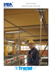
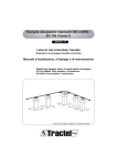
Freestanding safety railing system
English GB
Installation, user and maintenance manual
EN ISO 14 122-3
ARBO 3.16
www.tractel.com
G - Slanted post
Table of contents
Preliminary remarks
01 - Important safety information.
02 - Definitions and pictograms.
03 - Presentation.
04 - Preliminary study.
05 - Installation.
06 - Access to area protected by safety railing.
07 - Mandatory safety precautions.
08 - Malfunctions.
09 - Emergency procedure in the event of an incident.
10 - Disassembly.
11 - Periodic checks and servicing.
12 - Discarding of waste and protection
of the environment.
13 - Product markings.
p
p
p
p
p
p
p
p
p
p
p
p
05
05
05
06
09
09
11
12
12
12
12
13
Appendix 1 - Inspection sheet.
p 14
H - Dia. 30 mm rail with necking
I - Counterweight protection baseplate
p 13
p 13
J - Non-slip baseplate
A - Free end-fitting
K- Wall end-fitting
B - 14.8 Kg Concrete counterweight
L - Dia. 30 mm rail plug
C - 3 m Kick plate
M - Bag containing 100 rivets, 5.2 mm
D - Kick plate corner
E - 90° fixed rail corner
F - Adjustable rail corner
2
N - Bag containing 100 self-drilling
screws, dia. 3.9 x L 30 mm
Rail attachment system
G
B
H
H
M
J
Fig 1
I
Fig 2
Item 1
L
Item 3
Item 2
Fig 3
E or F
G
H
A
K
D
C
B
Fig 4
I
J
K
Fig 5
Fig 6
4
A
E
F
Fig 7
Preliminary remarks:
This manual covers the Tractel freestanding safety railing
equipped with concrete counterweights. Any information making
reference to a collective protection system refers to a collective
fall protection system.
With an aim to the on-going improvement of its products,
Tractel® reserves the right to make any changes which may
deem necessary to the equipment described in this manual,
without prior notice.
The Tractel® group companies and their certified distributors will
be happy to supply, on request, their documentation concerning
the present product line and other Tractel® products: Lifting and
pulling devices and accessories, worksite and building façade
maintenance equipment, safety systems for loads, electronic
load indicators, etc.
Contact the Tractel® network for your after-sales service and
periodic maintenance needs.
1. Important safety information
Danger:
1/ To ensure safe, efficient installation and use of the system, you
must first carefully read and understand the information
contained in this manual and strictly observe the rules and
recommendations given before you begin to install your safety
rail. Failure to observe instructions and recommendations given
in this manual can result in serious physical injury.
2/ Any person accessing the area protected by the safety rail
must be perfectly familiar with the information and instructions
given in this manual. Failure to observe instructions and
recommendations given in this manual can result in serious
physical injury.
3/ Safety railing users must be in possession of this manual.
Additional copies can be provided by Tractel® on request.
4/ The safety railing system is intended to protect hazardous
areas which are prohibited to unauthorized persons. All persons
penetrating the protected area must satisfy the physical aptitude
and professional criteria when working at heights.
5/ Since each safety railing system represents a site-specific
case, each safety railing installation must be preceded by a
complete technical study specific to the host structure receiving
the safety railing system. This technical study must be carried out
by a specialized, skilled technician to produce a technical
document for use by the installer.
6/ The safety railing installation must be performed using
appropriate means, and under safety conditions satisfying the
applicable regulations and standards of the country in which the
system is used. When installing the safety railing, the safety
railing user must take all the necessary measures to cover the
fall hazards to which the installer may be exposed due to the
configuration of the site.
7/ Use, maintenance and management of the safety railing must
be placed under the responsibility of persons fully aware of the
safety regulations and standards applicable to this type of
equipment in the country in which the system is used.
8/ The safety railing must never be used if not in good apparent
condition. If any defect is observed, access to all unauthorized
persons must be prohibited in the area protected by the safety
railing and the defect observed must be corrected before
continuing any work at heights on the protected area. The safety
railing must be inspected at least once every year.
9/ Each time the protected area is accessed, the user must
visually check the safety railing and make sure that it is in good
condition, and that no parts are missing or damaged. The user
must also check for any signs of corrosion, and ensure that all
the necessary signaling elements are in place at the required
locations and are legible. Any component of the safety railing
showing deformation must be replaced by a qualified person in
compliance with the instructions given in this manual.
10/ The safety railing must only be used as a passive collective
fall protection system. No other use is authorized. In particular,
the safety railing must not be used as a means of anchoring or
suspension, and must never be intentionally subjected to any
force or load.
11/ It is strictly prohibited to add or replace any parts of the safety
railing or to install any parts which are not supplied or
recommended by Tractel® . Any failure in this respect shall
release Tractel SAS from any responsibility.
12/ Tractel® declines any responsibility concerning installation, or
reinstallation after disassembly, of the safety railing in the area to
be protected when not performed in compliance with the
instructions of this manual, or in compliance with the regulations
and standards of the country in which the system is used.
13/ Never stay alone in the area protected by the safety railing.
Tractel® recommends that each operator be equipped with a
communication device in order to trigger an emergency or
assistance call in the event of an incident.
14/ It is prohibited to install or use the safety railing under
weather conditions not satisfying the working conditions
regulations in the country in which the system is used.
2. Definitions and pictograms
2.1 - Definitions
The following terms are used in this manual:
“Product”: Refers to the complete set of components forming
the safety railing.
“User”: Refers to the worksite foreman in charge of
management and safe use of the product described in this
manual.
“Operator”: Refers to the person or department operating the
product for which it is intended.
“Installer”: Refers to the person or department in charge of
assembling the components of the product received, installation
of the product so that it is ready to be used, disassembly and
dismantling, and transport for warehousing or storage.
“Technician”: Refers to a qualified person in charge of the
maintenance operations described and allowed to the user by
this manual; the user is understood to be qualified and familiar
with the product.
“Specialized technician”: Refers to a qualified person in
charge of the calculation operations and the installation
procedure described and allowed to the installer by this manual;
the installer is understood to be qualified and familiar with the
product.
“After-sales service”: Refers to a company or department
certified, by a company of the Tractel® group, to ensure aftersales service, or product repair operations.
“Safety railing”: A safety railing is an assembly forming a
barrier designed to protect persons against falls from heights.
The Tractel® safety railing forms part of the category of
permanent, passive and collective fall protection systems.
“Deck roof”: Roof with slope of between 0° and 10° with
respect to horizontal.
“Area prohibited to public:
Deck roof or any other area for which access is exclusively
reserved to authorized professionals working in the said area.
5
“Straight section”:
3.2 Composition of standard supply
Represents a straight part of the safety railing; the safety railing
can comprise several “straight sections” if equipped with a corner
piece.
The elements supplied are defined by the customer order. The
order must specify the delivery address, the name of the person
to contact on the worksite, the delivery date, the access
authorizations, the unloading facilities, the number of parts
required for the installation, and the layout of the railing elements
on the deck roof. On reception of the equipment, the customer
must check that the delivery slip and the equipment unloaded
complies with his order.
2.2 - Pictograms
”Danger”.
This pictogram refers to safety instructions aimed at preventing
injury to personnel, in particular fatal injuries, serious and minor
injuries, and possible damage to the equipment or environment.
”Important”.
This pictogram refers to information aimed at preventing a
failure, or damage to the product, but not representing any direct
safety hazard with respect to the operator’s life or health, or that
of any other persons, or with respect to possible damage to the
equipment or environment.
”Note”.
This pictogram refers to precautions to be taken to ensure safe
and efficient installation, use and maintenance of the system.
”Read user manual”.
Use Personal Protection Equipment (Fall protection).
Enter information in maintenance log or inspection log, as may
be the case.
3.3 Product definition
The Tractel® safety railing is a set of galvanized steel tubes
forming a safety barrier (fig.4, page 3). This system is a passive,
collective fall protection system designed to prevent persons
from falling, and is specially designed to protect persons working
on deck roofs with slopes not exceeding 10% with respect to the
horizontal. The safety railing is formed by posts slanted to 20°,
supporting two rigid rails. The top rail (also referred to as the
handrail) has a height of 1.1m above the walking surface. The
mid-rail is located 47cm below the top rail. The intermediate
posts are secured to the supporting surface by two 14.8kg
concrete counterweights; the end posts have four concrete
counterweights, each installed on the base of the post forming a
support (fig. 4, page 3). The two concrete counterweights,
installed on the cross-member, are seated on a protective plate
to prevent perforation of the insulation and waterproofing
materials (fig. 2, page 3). Use of the protective baseplate is not
required when the counterweights are set on the base rail. In this
configuration, the concrete counterweights set on the base rail
do not bear against the supporting surface. The front base of the
post is equipped with a non-slip baseplate which must
mandatorily be installed when assembling. The rails engage into
each other and must be riveted together (fig. 1, page 3). The rails
can be equipped at their ends with three types of terminating
systems: wall end-fitting, plug or free end-fitting (see figs. 3 and
4, page 3). When the safety railing is installed on a deck roof
without acroterion, kick plates are screwed onto the tube at the
lower part of the upright of each post (fig. 3, page 3). The
freestanding safety railing can be installed with variable angles
depending on the configuration of the area to be protected. For
these directional changes, the installer can use rigid 90° corners
or adjustable 0° to 180° corners.
3.4 Examples of safety railing layouts
3. Presentation
Figures 5, 6, 7, page 4
3.5 Regulations and standards applicable to product:
”Danger”.
Should the operator(s) be required to work outside the area
protected by the safety railing, the operator(s) must wear a
Personal Protection Equipment for fall protection, connected to
anchoring systems complying with the requirements of standard
EN 795.
The Personal Protection Equipment used must be CE certified,
manufactured in accordance with Directive 89/686/CEE, and
used in accordance with Directive 89/656/CEE.
Tractel® distributes a complete range of PPE equipment
compliant with the above directives.
3.1 General presentation
The Tractel® safety railing is a freestanding collective, passive
protection system. There is therefore no associated equipment.
The system is designed to mark out an area for which access is
prohibited to unauthorized persons, and to present the risk of
falls by operators. The system is installed on deck roofs with
slope not exceeding 10% with respect to the horizontal.
6
All regulations specific to each country must be observed.
The safety railing systems are not subject to CE marking, and
therefore not subject to the corresponding certification
procedures. However, the Tractel® safety railings have been
tested to satisfy standard EN ISO 14 122-3 by APAVE.
The Tractel® safety railings also satisfy the requirements of
circular ARBO 3.16 of the Dutch labor code.
With a force of 45 daN pushing horizontally against the top rail,
the following can be observed:
- No slippage.
- No tilting.
- No residual deformation after application of load.
Deformation of handrail under load is less than 30mm.
”Note”:
It is the installer’s responsibility to verify that the host structure
satisfies the requirements defined in the technical data package.
3.6 Description of components and functional
specifications
A –Free end-fitting:
Code: 111537
Dimensions: 150 mm x 2 mm x 3000 mm.
Supplied with two self-drilling screws.
Weight 7.06 kg.
D – Kick plate corner:
Code: 111577
Kick plate
rim
Kick
plate
Kick plate
corner
The free end-fitting is secured at the end of two rails when the
rails are not equipped with a wall end-fitting or a plug.
Material: galvanized steel.
Dimensions: tube dia. 30 mm, distance between centers 470 mm.
Supplied with 2 rivets, dia. 5.2 mm.
Weight 1.41 kg.
B - Concrete counterweight:
Code: 133585
The kick plate corner is secured to the end of the kick plate to
ensure the continuity of the kick plate for railing direction
changes. The kick plate is foldable and allows for angles of
between 0 and 180°.
Material: galvanized steel.
Dimensions: ht 150 mm x lg. 200 mm x th. 2 mm.
Supplied with two self-drilling screws.
Weight 0.03 kg.
E – 90° fixed rail corner:
Code: 111567
Concrete counterweight used to secure and stabilize the safety
railing.
Two concrete counterweights for intermediate and corner posts.
Four concrete counterweights for end posts.
Material: concrete.
Weight 14.8 kg.
C – Kick plate:
Code: 111527
The 90° rail corner is mounted on the end of the rail to obtain an
angle of 90°.
Material: galvanized steel.
Dimensions: tube dia. 30mm.
Supplied with 2 rivets, dia. 5.2 mm.
Weight 0.72 kg.
F – Adjustable corner:
Code: 111557
The kick plates are optional. These are secured to the base of
the posts if the deck roof is not equipped with an acroterion.
Material: galvanized steel.
7
The adjustable corner is mounted on the end of the rail to obtain
a corner adjustable between 0 and 180°.
Material: galvanized steel.
Dimensions: tube dia. 30mm.
Supplied with 1 rivet, dia. 5.2 mm.
Supplied with one 10 mm dia. clamping bolt.
Weight 0.91 kg.
G - Railing post:
The anti-perforation baseplate is positioned under the concrete
counterweight.
Plastic material.
Weight 0.06 kg.
J – Non-slip baseplate: (supplied with post)
Code: 133615
Code: 133575
Upright
Base rail
Crossmember
The freestanding railing post can be installed either as an end
post, or as an interior or exterior corner post, or as an
intermediate post. The maximum distance between two posts
is 1.50m.
Material: galvanized steel.
Weight 8.9 kg.
H – Top rail and mid-rail:
The non-slip baseplate is positioned under the front leg of the
post. The slope of the deck roof must not be greater than 10° with
respect to the horizontal under any circumstances.
Plastic material.
Dimensions: 210 mm X 210 mm.
Weight 0.05 kg.
K – Wall end-fitting:
Code: 111547
Code: 111517
The top and mid-rails are positioned on the railing post.
Material: galvanized steel.
Dimensions: dia. 30 mm lg 3 m.
Supplied with 1 rivet, dia. 5.2 mm.
Weight 4.1 kg.
I – Counterweight protection baseplate:
Code: 133605
8
The wall end-fitting is mounted on the end of the two rails when
the two rails are be secured to a wall at the end.
Material: galvanized steel.
Dimension: tube dia. 30mm. Male fitting
Supplied with 1 rivet, dia. 5.2 mm.
Supplied without wall fasteners.
Weight 0.30 kg.
L – Rail plug:
Code: 133595
The rail plug is fitted at the end of the two rails when the rails are
not equipped with a wall or free end-fitting.
Plastic material.
Dimension: dia. 30mm.
Weight 0.01 kg.
M – Rivet:
Code: 111587
Bag containing 100 rivets, dia. 5.2 mm. The rivets are used to
secure the following safety rail elements together:
Rail / Rail or Rail / Adjustable corner or Rail / Wall end-fitting or
Rail / Free end-fitting.
Material: Aluminum
N – Self-drilling screw:
Code: 111597
the installation to ensure that no damage occurs to the host
structure. The safety railing has a total weight, once installed, of
30 kg/ml. To prevent damage to the roof membranes, the installer
must first verify that the membranes are capable of withstanding
a minimum pressure of 1871.1 Pa. (1Pa = 1N/m2).
The study must also take account, if necessary, of possible
electrical equipment in the vicinity of the safety railing installation
in order to protect the installer against possible electrical
hazards.
The preliminary study must be recorded in a technical data
package comprising a copy of this manual, then submitted to the
installer with all the necessary information to implement the
guidelines of the study.
The technical data package must be prepared even if the study
is performed by the installer.
Any change to the configuration of the area protected by the
safety railing must show that the preliminary technical study has
been revised accordingly.
Tractel® can provide the preliminary study required for installation
of your safety railing, and can also provide studies for all special
safety railing installation needs.
5. Installation
5.1 - Tools required:
Assembly :
-
1 Mason’s line to align the posts.
1 Drilling machine with drill bit for attachment of wall end-fittings.
1 Set of wrenches to tighten the wall end-fitting bolts.
1 Hack saw to cut the rails.
1 Riveting machine with dia. 5.2mm fitting.
1 Cold-galvanization spray can.
1 Cutting pliers (to remove pallet bands).
1 Screwing machine with self-drilling screws if kick plates are
installed (self-drilling screws dia. 3.9xL30mm).
- Personal Protection Equipment (in particular, gloves, goggles,
Fall arrest device).
Disassembly:
- 1 Drilling machine with drill bit to remove rivets.
- 1 Set of wrenches to remove wall end-fitting bolts.
Bag containing 100 screws, dia. 3.9 x 30 mm. Used to secure
safety kick plates:
Kick plate / Kick plate or Kick plate / Kick plate corner.
Material: Stainless steel.
Dimensions: dia. 3.9 X 30 mm.
5.2 - Preliminary instructions and checks before
installation
”Danger”.
4. Preliminary study
”Important”:
Before installing the safety railing, a preliminary study by a
specialized technician must be carried out, particularly as
concerns the strength of the roof materials.
The system must take account of all applicable local regulations,
standards and trade practices, and the instructions given in this
manual. The installer technician or engineering department in
charge of the preliminary study must therefore be provided with
a copy of this manual.
The installer must study the hazards to be covered during the
installation procedure in accordance with the configuration of the
site, and the activity to be protected against falls.
Based on the study of these hazards, the installer must define
When installing or dismantling the safety railing, the
user must observe all applicable work regulations and legislation
in the country in which the system is installed. A risk analysis
must be performed with safety guidelines implemented to ensure
the health and safety of the installers. In all cases, operators
must be equipped with Personal Protection Equipment for fall
protection, manufactured in compliance with Directive
89/686/CEE and used in compliance with Directive 89/656/CEE.
All legislation applicable in the country of installation must be
observed when handling and storing the safety rail at heights;
this applies to both new worksites and worksites being
renovated.
The installer is understood as the prime contractor. If the installer
is not the prime contractor, the installer must obtain this manual
and ensure that all the instructions have been carried out.
9
In particular, the installer must ensure that all local regulations
and standards applicable to the safety railing are observed.
The safety railing installation must comply with the preliminary
study submitted to the installer.
The installation must, among others, be preceded by a visual
inspection of the site by the installer to ensure that the
configuration of the site is consistent with the configuration
covered by the preliminary study.
The installer must have the necessary skills to carry out the
safety railing installation procedures in compliance with the
preliminary study prepared and with the instructions given in this
manual.
Before performing the work, the installer must organize
the worksite to ensure that the work is performed under the
required safety conditions, in particular in accordance with the
applicable work regulations. The installer must set up all
necessary collective and individual protection systems to satisfy
the safety requirements.
”Important”:
The installer must verify that the deck roof has the necessary
strength to handle the weight of the safety railing and the weight
of the operators. The installer must also ensure that the deck roof
is capable of handling the weight of the pallets stored on the deck
before installation of the safety railing.
When installing and handling the safety railing, the installer must
ensure the protection and safety of the site environment:
- The safety railing must be protected against any contact with
electrical cables.
- All pipes and ducts must be protected against any contact with
the safety railing.
- The sealing membrane must be protected against any risk of
perforation due to handling of the loads or installation of the
safety railing;
- Ensure the emergency and working accesses are always clear.
- The immediate area around the worksite must be protected by
appropriate markers and signs during safety railing handling
and installation procedures.
The installer must begin by taking inventory of the parts received
and checking that the composition of the delivery comprises all
of the elements of the safety railing to be installed, based on the
technical data package of the preliminary study. The installer
must also check that all the necessary tools are available, as
indicated in this manual.
The Tractel® safety railing is designed to be installed on a deck
roof with slope not exceeding 10% with respect to the horizontal.
”Important”:
The safety railings are supplied on pallets weighing 550 kg max.
The installer must provide for the appropriate handling
equipment to unload the truck and to carry the materials to the
deck roof. A layout drawing of the concerned deck for the pallets
must be prepared in order to avoid any damage. Appropriate
slings and handling of the pallets must be provided by either the
user or the installer.
The pallets are supplied banded and(or) plastic-sheeted. Before
performing any handling operation, check that the pallet is in
good condition and that the packaging is not damaged. If this is
not the case, prepare the pallet packaging accordingly prior to
any handling.
10
5.3 – Setting up the safety railing
5.3.1 Assembly and installation:
• 1 Lay out the pallets on the deck roof in accordance with the
layout drawing defined by the installer. The pallets weight up to
550 kg max. Be sure to observe the maximum load capacity of
the deck roof, in particular the load capacity of the sealing
system. If necessary, use load distributors (distributors not
supplied by Tractel®.)
• 2 Using a mason’s line, position the posts at regular intervals
along the acroterion, and directly on the deck roof sealing
complex. For installation of the safety railing on a deck roof
which does not have an acroterion, provide a safety distance of
at least one meter with respect to the roof edge. If the deck roof
has gravel, sweep aside the gravel to prevent damage to the
sealing complex and make sure the posts adhere perfectly to the
deck roof. The posts must be properly aligned for the next step.
The interval between the posts and the distances of the first
and last posts at the corners are indicated on the technical data
package of the preliminary study.
• 3 Check that the non-slip baseplate (page 3, fig. 2, item J) is
properly positioned under the plate of each post (page 3, fig. 2,
item G). Place the protection plates as required under the
concrete counterweights (page 3, fig. 2, item I). Use of a
protective plate is not required for the two additional concrete
counterweights placed on the end posts (page 3, figs. 1 and 2).
Do not blank the drainage openings on the deck roof or any
other accesses which may be present on the deck roof.
• 4 Slide the rails, with the tapered end at the front, through the
holes of the posts along the two levels (top rail and mid-rail).
The rails will engage together by their male/female system
(page 3, fig. 1).
• 5 Insert rivets in the holes of the male and female rails, then
perform riveting. This will secure the various elements of the
safety railing together.
• 6 Position the two concrete counterweights on the base rail of
each post (see page 3, fig. 1). If a free end-fitting, plug or wall
end-fitting is used, install 4 concrete counterweights as shown
in the drawing on page 3, fig. 1. If the rails are terminated by
free end-fittings or rail plugs or wall end-fittings, the post must
be placed at least 40 cm from the end of the rail.
• 7 In accordance with the end of the straight rail section and the
requirements of the technical data package prepared during the
preliminary study:
- If the straight rail section is continued by a change of
direction, use a fixed 90° corner (page 3, item E), or an
adjustable corner (page 3, item F).
- If the straight rail section is interrupted, fit rail plugs at the rail
ends (page 3, item L), or a free end-fitting (page 3, item A), or
a wall end-fitting (page 3, item K) may be required.
Any rail or kick plate ends which have been cut must be treated.
Use a cold-galvanization spray can on the cut end. Tractel®
recommends use of appropriate PPE when performing such
operations (in particular, filtering mask, safety gloves). Always cut
the male part of the rail. In this case, the rail will have, at each of
its ends, a female part. Drill the rail at 25mm from one of the
female ends to a diameter of at least 6mm in order to rivet an end
fitting (male) such as a free end-fitting or a wall end-fitting, or a
fixed 90° or adjustable corner. If the remaining section of rail
measures more than 1 meter after it has been cut, this section
can be used on another part of a straight railing section.
For the wall end-fitting, use a 6mm diameter fastener appropriate
to the composition of the wall. It must have a shear strength of at
least 500 kg (refer to technical data sheet of dowel
manufacturer).
• 8 If the deck roof does not have an acroterion or if the height of
the acroterion is less then 100mm, install a kick plate. The kick
plate is secured to the post using self-drilling screws. The rim of
the kick plate must turn away from the post. For the end post,
refer to figure 3, page 3, item 2. For connection of the kick
plates together, overlay the kick plates with the rim turned away
from the post and secure them together using self-drilling
screws secured to the base of the post (page 3, fig. 3, item 1).
• 9 The rim of the corner kick plate (page 3, item 2) must be
positioned upward. In the corners, secure the corner kick plate
to the straight kick plates (page 3, item 1) using self-drilling
screws (page 3, item 1, 2). If the angle formed is not 90°, cut
the fold forming the kick plate corner using a hack saw along 50
mm, then fold the kick plate to the desired angle (see page 3,
item 3).
• 10 For gravel deck roofs, be sure to replace the gravel around
the safety railing posts before leaving the worksite.
5.3.2 - Safety markings :
”Note”:
You are required to comply with all local safety regulations
concerning safety markings for the area protected by the safety
railing system.
A nameplate must be placed at each access to the area
protected by the safety railing system.
5.3.3 - Checks before commissioning
Before commissioning, the safety railing installation must be
examined thoroughly at all visible parts to ensure that it complies
with all legal requirements, safety standards and, in particular,
standard EN ISO 14 122-3. Tractel® recommends, for this
purpose, use of a certified inspection organization.
The acceptance tests are performed on the initiative and for the
account of the user.
The tests must show compliance with standard EN ISO 14 122-3
and all other applicable local regulations.
”Danger”:
Before commissioning the safety railing, the installer must check:
- That all the concrete counterweights are correctly in place, i.e.
four at each end post and two at each intermediate post.
- That all the rails are correctly secured together by a rivet.
- That all the kick plates are correctly secured together and
screwed to the base of the posts.
- That the ends which have been cut are coated with a film of
galvanization spray and are free of any burrs or edges which
could injure an operator.
6. Access to area protected by safety railing
6.1 – Preliminary safety instructions.
”Danger”:
Each time a protected area is accessed, the operator must
visually inspect the safety railing and make sure that it is in good
condition and that no parts are missing or damaged. All elements
must be correctly secured together.
If there is any doubt as concerns the integrity of the safety railing
system, no work should be performed on the deck roof and
access to the roof should be blocked so long as the safety railing
has not been repaired by a qualified technician.
In the event of bad weather, you must comply with the labor code
regulations applicable in the country in which the safety railing is
installed.
6.2 Checks to be performed:
”Danger”:
• Check that the safety railing is properly aligned.
• Check that all the necessary posts, rails and kick plates are in
place.
• Check that all the necessary concrete counterweights are in
place, in accordance with the instructions of this manual.
• Check that all the rivets are correctly installed.
• Check that all the necessary baseplates are installed:
- under the post plates.
- under the counterweights.
• Check that all the components of the safety railing (rails, posts)
are free of any deformation or corrosion, and that no
components are uncoupled.
• In those countries requiring installation of a safety marking
plate, check that the plate is in place and is compliant with the
local regulations.
ANY DAMAGED COMPONENT MUST BE REPLACED.
11
7. Mandatory safety precautions
To ensure user safety, the Tractel® safety railing must be used in
full compliance with the instructions given in this manual. The
operator must refrain from any of the following unsafe practices:
8. Malfunctions
Malfunction
Corrective action
Rail uncoupled
Couple the rails and secure with
rivet (Steps 4 – 5 § assembly).
Do not:
Missing rivet
Fit a new rivet (Assembly section,
step 5).
- Use the safety railing for any purpose other than as a collective
fall protection system.
- Use a safety railing which has already stopped a fall, without
prior inspection of the safety railing by the manufacturer or by
an after-sales agent approved by the manufacturer.
- Use the safety railing for a period exceeding 12 months without
having it inspected by Tractel®, a technician or an after-sales
agent approved by Tractel®.
- Use the safety railing or one of its components as an anchor
point or as a suspension for a PPE or any other element.
- Install the safety railing without having first defined an
emergency procedure in the event of an incident.
- Cross over the safety railing without being equipped with a
Personal Protection Equipment for protection against falls.
- Climb on the rails of the safety railing or intentionally push
against the safety railing.
- Use the safety railing as a fall protection system in an area
which is freely accessible to the public. Access to the protected
area must be prohibited to unauthorized persons.
- Destabilize the safety railing by intentional bumping or impact.
- Modify any parts of the safety railing or fit any parts which are
not supplied or recommended by Tractel®.
- Modify or move the safety railing while it is being used.
- Disassemble or modify the safety railing without first having a
preliminary study conducted by a qualified technician having
the necessary skills.
- Use the safety railing in an explosive atmosphere.
- Install the safety railing in an area having a slope exceeding 10°
with respect to the horizontal.
- Install or use the safety railing when the area to be protected
shows any signs of snow or ice.
- Perforate or puncture the host structure, in particular the
sealing roof system on which the safety railing is mounted
without the prior written approval of the building manager.
- Work alone in the area protected by the safety railings.
Missing component
Add a new component. (Assembly
section).
Deformed component
Remove deformed component,
remove rivets or screws.
Install new component. (Assembly
section).
Signs of corrosion
Analyze extent and seriousness of
corrosion.
For surface corrosion:
- Eliminate corrosion (sand paper or
rust remover)
- Apply cold-galvanization spray
For penetrating corrosion:
- Remove corroded element, remove
rivets or screws.
- Install new element (Assembly
section).
”Danger”:
The maintenance operations must only be performed by qualified
technicians, installers or after-sales agents, approved by the user
and appropriately qualified with respect to the requirements of
this manual.
9. Emergency procedure in the event
of an incident
”Danger”:
Before commissioning the safety railing, the user must define an
emergency and intervention procedure to be applied in the event
of an incident occurring in the area protected by the safety railing.
The operators must be equipped with a means of communication
to trigger an emergency or assistance call in the event of an
incident.
10. Disassembly
The Tractel safety railing is not intended to be disassembled
then reassembled.
®
”Danger”:
Before performing the work, the installer must organize the
worksite to ensure that the work is performed under the required
safety conditions, in particular as concerns labor regulations.
All necessary collective and individual protection systems must
be set up to meet the safety requirements.
During the disassembly procedure, the handling and transport
operations are carried out under the responsibility, and for the
account of, the user.
If the disassembled safety railing is to be stored on pallets on the
deck roof, the installer must make sure that the roof has the
capacity to receive the weight of the pallets before they are
12
evacuated. The installer must define a layout drawing for layout
of the pallets on the deck roof.
The supply of appropriate slings and handling equipment for the
pallets are for the account of the user or installer in charge of the
disassembly intervention.
Remove the screws and rivets securing the rails and kick plates
together.
Remove the screws from the wall-fittings.
Uncouple the rails and kick plates from each other.
Remove the concrete counterweights, the posts, the counterweight protection plates and the non-slip plates, one after
another.
Safety rail leg
11. Periodic checks and servicing
11.1 - Periodic checks
The safety railing system is not a Personal Protection
Equipment. It is a passive protection system and therefore not
subject to the legal obligation of periodic inspection. However,
Tractel® recommends an annual inspection to ensure that the
safety railing is in good safe condition.
11.2 - Servicing
The safety railing is made of hot-galvanized steel in accordance
with the recommendations of standard NF EN 1461 and
ARBO 3.16. For this reason, no specific maintenance is required.
However, to preserve the quality of the protection system, we
recommend a visual inspection of the overall safety railing
system prior to each intervention in the area protected by the
safety railing.
12. Discarding of waste and protection of
the environment
On final dismantling of the product, recycling of the safety railing
must be performed by a specialized company. The safety railing
is formed by three basic products:
• Concrete counterweights: to be handled as rubble.
• Non-slip and counterweight protection plates: to be handled as
synthetic fiber.
• Posts, rails and kick plates: to be handled as a ferrous metal
product.
13. Product markings
”Read user manual”.
Traceability of the Tractel® safety railing is ensured by a
nameplate at the base of each post.
The nameplate contains the following information:
a- Tractel® logo.
b- Production order No. (Batch No.).
c- Production year.
d- Welder No.
13
APPENDIX 1
Inspection sheet
Tractel freestanding safety railing
Designation:
Check that the safety railing is properly aligned.
Check that all the necessary posts, rails and kick plates are in place.
Check that all the necessary concrete counterweights are in place, in accordance with
the instructions of this manual.
Check that all the rivets are correctly installed.
Check that all the necessary baseplates are installed:
- under the post plates.
- under the counterweights.
Check that all the components of the safety railing (rails, posts) are free of any deformation
or corrosion, and that no components are uncoupled.
In those countries requiring installation of a safety marking plate, check that the plate is in
place and is compliant with the local regulations.
Any damaged component must be replaced.
Inspection date:
Name and position of inspector:
Inspector signature:
14
15
F
TRACTEL S.A.S.
RN 19 Saint-Hilaire-sous-Romilly, B.P. 38
F-10102 ROMILLY-SUR-SEINE
T: 33 3 25 21 07 00 – Fax: 33 3 25 21 07 11
L
SECALT S.A.
3, Rue du Fort Dumoulin – B.P. 1113
L-1011 LUXEMBOURG
T: 352 43 42 42 1 – Fax: 352 43 42 42 200
D
GREIFZUG Gmbh
Scheidtbachstrasse 19-21
Postfach 200440
D-51434 BERGISCH-GLADBACH
T: 49 2202 10 04 0 – Fax: 49 2202 10 04 70
GB
TRACTEL IBÉRICA S.A.
Carretera del medio 265
E-08907 L’HOSPITALET (Barcelona)
T: 34 93 335 11 00 – Fax: 34 93 336 39 16
I
TRACTEL ITALIANA S.p.A.
Viale Europa 50
I-20093 Cologno Monzese (MI)
T: 39 2 254 47 86 – Fax: 39 2 254 71 39
NL
DK
TRACTEL BENELUX B.V.
Paardeweide 38
NL-4824 EH BREDA
T: 31 76 54 35 135 – Fax: 31 76 54 35 136
P
TRACTEL POLSKA Sp. z o.o.
Al. Jerozolimskie 56c
PL-00-803 Warszawa
CND
TRACTEL LTD
1615 Warden Avenue Scarborough
Ontario M1R 2TR
T: 1 416 298 88 22 – Fax: 1 416 298 10 53
CN TRACTEL CHINA
1507 Zhongyue Bldg
225 Fujian Zhong road
SHANGHAI 20001
CHINA
TRACTEL UK Ltd
Old Lane, Halfway
SHEFFIELD S20 3GA
T: 44 114 248 22 66 – Fax: 44 114 247 33 50
E
PL
SGP
TRACTEL SINGAPORE Plc
50 Woodlands Industrial Parc E
Singapore 75 78 24
T: 65 757 3113 – Fax: 65 757 3003
UAE
TRACTEL MIDDLE EAST
P.O. Box 25768
DUBAI
UNITED ARAB EMIRATES
T: 971 4 3430 703 – Fax: 971 4 3430 712
USA
TRACTEL Inc
110, Shawmut Road, ste2
Canton MA 02021 USA
T: 1 781 401 32 88 – Fax: 1 781 826 36 42
LUSOTRACTEL LDA
Alto Do Outeiro Armazém 1 Trajouce
P-2775 PAREDE
T: 351 21 444 20 50 – Fax:351 21 445 19 24
© Copyright – All rights reserved. TRACTEL SAS
134685 02-ind00-05/2008