1
A Technical Overview
(Second Edition)
Romilly Bowden
November 1999
629.8
ROH99
FISHER-ROSEMOUNT
Managing The Process Better;'
CONTENTS
PREFACE.
CHAPTER 1. "SMART" INSTRUMENTS AND THE HART PROTOCOL.
1.1
1.2
629.8 ROH99
Bowden, Romilly
HART Field Communications
Protocol: a technical
overvier
(2nd ed.)
DATE DUE
BORROWER'S NAME
1.3
1.4
1.5
1.6
1.7
1.8
1.9
1.10
1.11
1.12
1.13
1.14
1.15
1.16
1.17
Introduction.
"Smart".
Configurators.
Digital communication.
Reading the measured variable by digital communication.
Additional information.
Multidrop communication.
The HART protocol.
Universal commands.
Common-practice commands.
Device-specific commands.
Output devices.
HART products.
Device Description Language.
Fieldbus.
The HART Communication Foundation..
Sununary.
Figures: 1-1
1-2
1-3
1-4
1-5
A Smart system.
Multidrop communication.
The HART signal.
The HART message structure.
A Fieldbus system with hierarchical structure.
Tables: 1-1
1-2
1-3
1-4
1-5
Universal commands.
Some common-practice commands.
Examples of device-specific commands.
Some available HART products.
Major features offield devices using HART.
F;880urce Center
Fisilel'~Ftos8mount
SV$tsms
Austin Texas·
CHAPTER 2. THE PHYSICAL SIGNAL.
2.1
2.2
2.3
2.4
2.5
2.6
Introduction.
Frequency-shift keying.
Signal levels.
The connection loop.
Active-source devices.
Multidrop operation.
-i -
2.7
2.8
2.9
2.10
2.11
2.12
2.13
2.14
2.15
2.16
2.17
2.18
Device characteristics.
Signal attenuation and distortion - the 65 JlS limit.
Cabling.
Grounding.
Power supply.
Analogue signal bandwidth.
Output devices.
Other devices.
Intrinsic safety barriers.
Voltage-mode HART.
RS-485 HART.
Summary.
Figures: 2-1
2-2
2-3
2-4
The two-wire current loop.
The current loop for an active-source field device.
A two-wire multidrop loop.
Mixed two-wire and active-source devices.
Tables: 2-1
2-2
2-3
2-4
2-5
2-6
HART signal levels.
Impedance specifications.
Cable parameters.
Some typical cables.
Maximum length for typical I mm2 cables.
Power supply specifications.
CHAPTER 3. TRANSACTION PROCEDURE, CODING AND MESSAGE
STRUCTURE.
3.1
3.2
3.3
3.4
3.5
3.6
3.7
3.8
3.9
3.10
3.11
3.12
3.13
3.14
3.15
3.16
3.17
3.18
Introduction.
Master-slave operation.
Multimaster operation.
Transaction procedure.
Burst mode.
Character coding.
Message format.
Long and short frame formats.
Preamble.
Start character.
Address.
Command.
Byte count.
Status.
Data.
Checksum.
Example transactions.
Summary.
- ii -
Figures: 3-1
3-2
3-3
3-4
3-5
3-6
Character format.
The HART message structure.
Short frame address structure.
Long frame address structure.
A short frame format transaction.
A long frame format transaction.
Tables: 3-1
3-2
Summary of timing rules.
Start characters.
CHAPTER 4. COMMANDS, DATA AND STATUS.
4.1
4.2
4.3
4.4
4.5
4.6
4.7
4.8
4.9
4.10
4.11
4.12
4.13
4.14
4.15
Tables: 4-1
4-2
4-3
4-4
4-5
4-6
4-7
4-8
4-9
4-10
Introduction.
Commands.
Universal commands.
Common-practice commands.
Device-specific commands.
Commands #0 and #1 I.
Commands #1, #2 and #3.
Command #6.
Commands #12 to #19.
Data.
Enumerated items.
Multivariable transmitters.
Command summary.
Status.
Summary.
Universal commands (summary).
Common-practice commands (summary).
Enumerated variables.
Universal commands in HART Revision 5.
Universal commands in HART Revisions 2, 3 and 4.
Common-practice commands.
Response .codes.
Command response classification.
Multiple-meaning command response codes.
Field device status.
- iii -
CHAPTER 5. DEVICE DESCRIPTION LANGUAGE.
5.1
5.2
5.3
5.4
5.5
5.6
5.7
5.8
Introduction.
What is Device Description Language?
Benefits ofDDL.
Creating a Device Description.
Using a Device Description.
Distribution of Device Descriptions.
Fieldbus.
Summary.
Figures: 5-1
5-2
5-3
Fragments of a Device Description.
Entries in the standard dictionary.
Generation and use of a Device Description.
Tables: 5-1
5-2
Principal DDL object types.
Principal DDL data types.
GLOSSARY.
FURTHER INFORMATION.
PREFACE
The HAR'f® protocol has become a de facto standard protocol for communication with Smart field
devices in industrial process applications. HART is an acronym for "Highway Addressable Remote
Transducer". The HART specification defines the physical form of transmission, transaction
procedures, message structure, data formats, and a set of commands. It also allows a designer the
freedom to define device-specific commands where appropriate.
The HART protocol was originally developed by Rosemount Inc. However, to encourage the use of
digitally communicating field devices, Rosemount has passed all rights in the protocol to the HART
Communication Foundation, and the HART protocol is freely available for anyone to use. An everincreasing number of suppliers offer products using this protocol.
This booklet introduces the HART protocol, and gives some technical details of the current
implementation (Revision 5.3). We hope it will help you to understand the features and benefits of
the HART protocol, how it works and what it can do. It may also help you understand the complete
specification documentation, by providing an alternative less-formal treatment. But it cannot be
regarded as a replacement for the complete HART specification - if you are designing a HARTcompatible instrument or host system, you will need the complete specification. This booklet does
not cover all the details of HART, nor will it necessarily be kept up-to-date. Under no circumstances
should it be taken as definitive.
The booklet is designed to be read sequentially, with new topics being introduced as they are needed,
sometimes at a simple level in one place, then with more detail later. To make it easier to use for
reference, it has short sections, each on a specific topic. The index at the end of the booklet will
direct you to one or more sections dealing with any listed subject.
INDEX.
Chapter I provides an overview of "smart" instrumentation and the HART protocol. Chapter 2
describes the physical signalling method and the transmission medium. Chapter 3 describes the
transaction procedure, and the coding of characters and other data. Chapter 4 describes the
commands used to operate a field device, and includes extensive reference tables. Chapter 5
introduces the Device Description Language, an important technique for interoperability.
A glossary of technical terms and abbreviations follows Chapter 5. The explanations given are
aimed particularly at the relationship of the term to the HART protocol. You may like to refer to this
for further explanation of any unfamiliar words or concepts, or as a reminder of HART usage.
A list of further HART-related documents, software tools and contact addresses is also included for
reference.
The author would welcome any comments or suggestions on the content or presentation of this
booklet.
HART is a registered trademark of the HART Communication Foundation.
- iv-
-v-
CHAPTER 1. "SMART" INSTRUMENTS AND THE HART PROTOCOL
1.1
Introduction
This chapter introduces the main concepts of digital communication with field instruments, as
implemented by Fisher-Rosemount in its "Smart Family" of transmitters using the HART protocol.
1.2
"Smart"
The description "smart" for a field device has been used in the sense of "intelligent", to describe any
device which includes a microprocessor. Typically, this would imply extra functionality, above what
had previously been provided in similar non-microprocessor-based instruments. For example, a
smart transmitter might provide better accuracy through the use of a numerical calculation to
compensate for sensor non-linearity or temperature dependence. It might be able to operate with a
variety of different sensor types. It might combine two or more measurements into a single new
measurement (for example volume flow rate and temperature into mass flow). Or it might allow.
re-ranging or semi-automatic calibration. Often, it would provide internal diagnostic self-test
functions to simplify maintenance procedures.
As well as giving better performance, this extra functionality can reduce the processing needed in the
host (control system), and may also result in a range of instruments being reduced to a single model,
with advantages in manufacturing and inventory management.
[This page intentionally blank]
1.3
Configura tors
To make use of these extra features, "smart" devices usually need a plug-in "configurator", a box
with a display and a number of push-buttons for the user to set up and control the instrument.
(Providing these as a local operator interface on the device itself is generally too expensive, and
clumsy, for field-mounting units, but may be appropriate for more complex panel-mounting
instruments.)
1.4
Digital communication
A logical next step is to allow the instrument and its "configurator" box to be separated by a greater
distance, by using properly-specified serial communications between them. A further step combines
this communication on to the two wires already used to connect the device back to the central control
room. This brings us to Fisher-Rosemount's present use of the word "smart", to describe field
devices in which the analogue signal, digital communication and (generally) power co-exist on the
same pair of wires.
With such instruments, the advantages of digital communication are obtained, while retaining
compatibility with the analogue signal inputs required by existing systems. Now, in addition to
using digital communication to set up and control the field device, it becomes possible to read the
- vi-
- 1-
measured variable over the communication linle Without modification, these instruments are ready
for fully-digital system use.
Further, it can be used to keep records of maintenance-related activities such as the date oflast
calibration. Automated instrument management systems become possible, using accurate up-to-date
infonnation from the device itself.
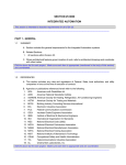
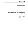
1.7
Smart transmitter
Multidrop communication
If the measured variable is going to be read by digital communication, the analogue 4 to 20 rnA
signal is no longer required. It then becomes possible to connect mUltiple field devices in parallel to
a single pair of wires, and to communicate with each one in turn to read its measurement (or other
data). To do this, each device must have an "address", to which it will respond, and each request
from the host must include this address as part of the message.
4 to 20 rnA + digital communication
(twisted pair cab/e)
Personal
computer
This "multidrop" connection can significantly reduce the cost offield wiring and host input interface
electronics, and may be valuable in monitoring systems. Note, however, that the use of a cyclic scan
means that each measurement is only examined at intervals, and the cycle time for a complete scan
may be too long for high-speed control loops.
Handheld
communicator
C'configurato~')
HART modem
I multiplexer
Figure 1-1. A Smart system
single twisted pair cable ...
1.5
Reading the measured variable by digital communication
Using digital communication to read the measured variable, it becomes possible for a single
instrument to provide more than one measurement. (Thus, for example, a Corio lis mass flow
transmitter can provide mass flow rate, process temperature, density and totalized mass flow in a
single message.) It becomes possible to check on the continued good health of the field device every
time a measurement is made, giving a valuable increase in confidence and security. There is a
further gain in accuracy, in that the intennediate steps of digital-to-analogue and analogue-to-digital
conversion to and from the 4 to 20 rnA signal are omitted.
Note, however, that the time taken to communicate the message adds an extra delay (dead time) to
the measurement, which could adversely affect the control of fast loops. If this is a problem, it will
be preferable to use the analogue value for control purposes. The higher communication speed of
Fieldbus (see 1.15 below) will eventually remove this limitation.
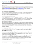
1.6
Additional information
Digital communication also makes it worthwhile to keep additional infonnation in the field device, to
be read out when required. This leads to several useful possibilities. It can give process-related
infonnation such as tag number and a description of the measurement, and the instrument's calibrated
range and units. Or it can give infonnation about the device itself, acting as an electronic "label".
Controller
or monitoring
system
Gauge
pressure
Differential Temperature
pressure
Figure 1-2. Multidrop communication
1.8
The HART protocol
To use these extra features easily with a range of different hosts and field devices, a communication
standard is needed. This has to include specifications for the physical fonn of transmission,
transaction procedures, message structure, data fonnats, and a set of commands to perfonn the'
required functions.
The HART protocol was developed by Rosemount Inc. for this purpose. HART is an acronym for
"Highway Addressable Remote Transducer". To encourage the use of digitally communicating field
devices, Rosemount Inc. has passed all rights in the protocol to the HART Communication
Foundation (HCF) and the HART protocol is freely available for anyone to use. See 1.16 below.
health. There mayor may not be "data" included in a message, depending on the particular
command. Two or three message transactions can be made each second.
.
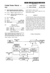
The remainder of this booklet describes the HART protocol in detail. In brief, HART uses the Bell
202 standard frequency shift keying (f.s.k.) signal to communicate at 1200 baud, superimposed at a
low level on the 4 to 20 rnA analogue measurement signal. Having an average value of zero, an f.s.k.
signal causes no interference with the analogue signal (see Figure 1-3).
I I I I I
STRT
ADDR
COM
BCNT
[STATUSI
I
L
l ,. ,,~
Data (0 to 25 bytes)
Command. communication and device
j.......... "'r"
status (2 bytes, from slave to host only)
+O.5mA··E\Mi··
............
-O.5~:. l·.··::··.:::···::j·:::i ..:·...::...:·!i...:
20mA
!
1200Hz
'I'
Byte count (of status and data fields)
Command
\
2200Hz
'0'
Addresses (source and destination; 1 or 5 bytes)
Start character
Preamble (5 to 20 bytes, hex FF)
R
Analogue
Figure 1-4. The HART message structure
signal
c
1.9
4mA
C=Command
R= Response
The high frequency HART signal is composed of sine waves
at 1200 Hz and 2200 Hz. This signal has an average value
of zero, so does not affect the analogue signal. It is removed
by standard analogue input circuit fiHerlng.
Universal commands
The commands of the HART protocol are defined in three groups. The first group, "universal
commands", provide functions which are implemented in all field devices. Table 1-1 lists these. See
Table 4-4 for more details.
1.10 Common-practice commands
Time (sec)
The second group, "common-practice commands", provide functions common to many field devices,
but not all. If a device implements these functions, these commands should be used to perform them.
Table 1-2 lists some of these. See Table 4-6 for a complete list and more details.
Figure 1-3. The HART signal
HART is a master-slave protocol- a field device only replies when it is spoken to. There can be two
masters (a control system and a hand-held HART Communicator, for example). Up to IS slave
devices can be connected to a single multidrop cable pair (up to four devices, in intrinsically-safe
applications).
.
Each message (see Figure 1-4) includes the addresses of its source and its destination, to ensure that
it is received by the correct device, and has a "checksum" to allow detection of any corruption of the
message. The field device's status is included in every reply message, indicating its continued good
-4-
1.11 Device-specific commands
The third group, "device-specific commands" (previously called "transmitter-specific"), provide
functions which are more or less unique to a particular field device. Table 1-3 lists a few examples.
-5-
Table 1-1. Universal commands.
Table 1-3. Examples of device-specific commands.
Command number(s)
Command(s)
Device
0, 11
Read manufacturer and device type
Function
128, 129
1151S
Read or write materials of construction
1
Read primary variable (PV) and units
130, 131
3044C
Read or write sensor type
2
Read current output and percent of range
138, 139
8712
Read or write low flow cutoff value
3
Read up to four pre-defined dynamic variables
146
9712
Start, stop or clear totalizer
6
Write polling address
146, 147
1054A
Read or write alarm relay set point
12,17
Read or write 32-character message
153, 154
9712
Read or write density calibration factor
13,18
Read or write 8-character tag, 16-character description, date
166
3680
Write gamma source
14
Read sensor serial number and limits
15
Read transmitter range, units and damping time constant
16,19
Function
Command number(s)
33
Read a selection of up to four dynamic variables
34
Write damping time constant
35
Write transmitter range
40
Re-range (set span and zero)
Set fixed output current
41
Perform self-test
42
Perform master reset
43
Trim (set) PV zero
44
Write PV units
45,46
47
Trim DAC zero and gain
Write transfer function (square root, linear, etc.)
48
Read additional device status
49
Write sensor serial number
50,51
1.12 Output devices
Read or write final assembly number
Table 1-2. Some common-practice commands.
36, 37
Function
Read or write dynamic variable assignments
- 6-
So far in this chapter, we have described "smart" and HART in terms of measuring instruments and
inputs to control and monitoring systems; indeed this is what HART was originally designed for.
But the protocol is now also used for output devices - valve positioners and current-to-pressure
transducers. Significant benefits are obtained by making enhanced diagnostic information available
from these devices, to the control system or to a maintenance management computer.
1.13 HART products
A wide range of products is now available using the HART protocol. Table 1-4 shows many of
these, and notes the areas in which Fisher-Rosemount offers products. "The HART Book",
published from time to time by GGH Marketing Communications, is a useful reference source.
1.14 Device Description Language
The HART "Device Description Language" (DOL) is a formal language (like a simple computer
programming language), which lets a device designer describe completely and unambiguously what
a field instrument looks like when you talk to it through the "window" ofits digital communication
link. The Device Description includes a definition of accessible variables, commands, and operating
procedures. It also includes the menu structure which a host device can use for a human operator.
Device Descriptions make it easy to upgrade hosts to support new field devices, without re-writing
software. Device Descriptions can be used by any suitably-designed host device (handheld
communicator, control system or instrument management system) to automatically provide a correct
and complete user interface for each field device. Device Descriptions allow interoperability and a
degree of interchangeability between smart instruments from different manufacturers, even though
the instruments' functions may be implemented in different ways. Users can choose the best
instrument for each application, without being locked in to a single supplier for the complete system.
-7-
Although simple host systems can be designed without using De~ice Descriptions, they will be
limited to using universal and common-practice comm~ds, or w~ll ~eed custom upg~ades for ~a~h
new field device. See Chapter 5 for more detail on Device DescnptlOns and the Device DescnptlOn
Language.
bus, multidrop and intrinsically-safe operation are required features, but compatibility with analogue
systems is not retained. Several communication speed options are proposed.
Table 1-4. Some available HART products
Field devices
Host devices
Miscellaneous
components
Software
1.15
FisherRosemount
products
Description
Product
category
Analytical (pH, conductivity, flue gas oxygen, ORP, RCL, DO)
Density (Coriolis, nucleonic).
. .
Flow (DP, magnetic, vortex, ultrasonic, ga~ flow I mul.tlvanable)
Level (displacement, capacitive, hydrostallc, ultrasonic,
microwave, impedance)
Mass flow (Coriolis, thermal, vortex, multivariable)
Pressure (absolute, differential, gauge)
Temperature (RTD, thermocouple, infra-red, mV)
I-to-P transducer
Valve position controller
Process controller (PID, advanced)
0/
0/
0/
0/
Distributed Control System (DCS)
Programmable Logic Controller (PLC)
Single Loop Controller
Handheld Communicator
Handheld PC
Flow Computer
Hydrostatic Tank Gauge
0/
Modems (standalone, PC card: ISA, PCMCIA)
Modem IC chips
Multiplexers
Protocol converters
Intrinsic safety barriers and repeaters
0/
0/
0/
0/
0/
0/
0/
0/
0/
0/
0/
0/
Fieldbus
Fisher-Rosemount continues to work with others, both in the Fieldbus Foundation and in t~e ~ational
d . t ational standards committees, to define a worldwide higher-speed field commumcatlOn
referred to as "Fieldbus". Like HART, this is designed to be used as the lowest
hierarchical structure of functional devices and
such as that
shown in Figure 1-5. However, the perfonnance being demanded IS slgn~ficantly greater than that
provided by today's instruments, both in communication speed and quantity of data. Power over the
~ ~n ~rngenerallY
~e:l ~ ~
Field devices
Figure 1-5. A Fieldbus system with hierarchical structure
0/
Process monitoring
SCADA
Telemetry
Instrument configuration
Instrument calibration
Instrument diagnostics
Instrument I maintenance management
Control system natwork
Today's smart instruments are part of a continuing evolutionary trend, from pneumatic instruments
(3 to IS psi), through analogue electronic (4 to 20 rnA) and simultaneous analogue/digital
communication (HART) to full digital communication (Fieldbus). This is part of the general move
towards a wider use of digital communication in instrument and control systems, leading to eventual
integration with Management Infonnation Systems.
The HART protocol already allows instrument manufacturers and users to get many of the benefits
of, and to gain experience with, digital field communications, while keeping compatibility with
existing analogue systems. This experience will help both manufacturers and users to judge the
benefits and problems of using digital communication in plant operation. We expect the HART
protocol to have a long life, alongside Fieldbus, for upgrades and extensions to existing systems, and
for applications where compatibility with analogue signals continues to be important.
1.16 The HART Communication Foundation
The HART Communication Foundation (HCF) is a not-for-profit Foundation dedicated to promoting
and supporting the use of the HART protocol. To encourage the widespread use of HART,
Rosemount Inc. has transferred the registered trademark and ail rights in the protocol to the HCF.
The protocol remains open and free for all to use without royalties. The HCF is supported by its
members (over 60 at a recent count), and can provide documentation, training and support to all users
or interested parties.
communi.cat~on.networks,
-8-
- 9-
CHAPTER 2. THE PHYSICAL SIGNAL
1.17 Summary
This chapter has described the evolution of the present state of "s~art" fi~ld ~evices and the .HA~T
protocol. Major features are summarised in Table 1-5 below. ThIS combl~atlOn of features. IS umque
to the HART protocol; the resulting benefits provide powerful reasons for mstrument supphers and
users to make use of this protocol.
Table 1-5. Majorfeatures of field devices using HART
2.1
Introduction
This chapter describes the physical signalling method and transmission medium of the HART
protocol. These correspond to layer 1 - the physical layer - of the OSI protocol reference model.
2.2
Frequency-shift keying
Benefits
Features
"Smart" electronics
Improved accuracy. Wider functional range reduces
inventory.
HART - an "open" protocol.
Users are not locked in to a single supplier.
Two-wire system.
Can use existing field wiring.
Simultaneous analogue and digital
communication.
Compatible with existing analogue systems, but ready for
fully-digital systems.
Multidrop option.
Allows economy in field wiring.
Multimaster protocol.
Can ·use hand held communicator without disturbing the
control system.
Status with every message.
Improved data integrity.
Remote self-test and adjustment. _
Invaluable for inaccessible instruments.
Extensive on-line instrument data.
Accurate records for maintenance and inventory control.
Access to on-line diagnostic data.
Improved performance. Reduced cost of maintenance
procedures.
Universal and common-practice
commands.
Operation with new devices.
Device-specific commands.
Allow innovation in field device design.
Read device identity (tag).
Easy tracing of field wiring.
"Set output" command.
Easy checking of loop integrity.
Bell 202 standard.
Proven reliability. Low cost modem ICs available to
manufacturers.
Device Description Language.
Interoperability of devices from different suppliers.
HART uses a frequency-shift keying technique to superimpose digital communication on to the 4 to
20 rnA current loop connecting the central system to the field device. Two different frequencies
(1200 Hz and 2200 Hz respectively) are used to represent binary I and O.
These sine-wave tones are superimposed on the d.c. signal at a low level (see Figure 1-3). The
average value of a sine-wave signal is zero, so no d.c. component is added to the existing 4 to 20 rnA
signal, no matter what the digital data may be. Consequently, most existing analogue instruments
continue to work as usual- the low-pass filtering usually present effectively removes the
communication signal. t
The data rate used is 1200 baud. That is to say, binary digits are transmitted at a rate of 1200 per
second. This means that a 1 is represented by a single cycle of 1200 Hz, while a 0 is represented by
approximately two cycles of2200 Hz.
This choice of signalling frequencies and transmission rate accords with the American "Bell 202"
standard, one of several used to send digital information over telephone networks. As a result of this,
suitable integrated circuit modem chips are widely available at low cost. In the USA, it is
permissible to transmit this signal over the public telephone network. Unfortunately, this standard is
not approved for use over European public telephone networks. (In Europe, back-to-back modems
could be used to convert Bell 202 to RS-232 and thence to CCIrr standard V.22 or V.23, if
operation over a public network is required).
2.3
Signal levels
The HART protocol specifies that master devices (a host control system or a hand-held
communicator) transmit a voltage signal, whereas slave (field) devices transmit a current signal.
(Recall that the normal operation of a 2-wire transmitter is to control the loop current; it is easy to
extend this control to generate the small high-frequency component of the HART communication
signal.)
t Fast sampling analogue-to-digital converters used in some control systems (especially PLCs) may be troubled
by the presence of the HART signal. Using a voltage-sensitive input and an external filter should resolve this
problem. (A single-pole 10 Hz low-pass filter reduces the communication signal to a ripple of about ±O.OI %
ofthe full-scale analogue signal).
- 10-
- 11 -
The current signal is converted into a corresponding voltage by the loop load resistor, so all devices
use voltage-sensitive receiver circuits. The specified peak-to-peak signal levels are shown in
Table 2-1. Ideally, the wave shape is sinusoidal, but a trapezoidal waveform is acceptable within
limits (see the full HART specification). A square wave is not acceptable.
+24V
A
Table 2-1. HART signal levels
Master transmitted signal
min 400 mV p-p
max 600 mV p-p
Slave transmitted signal
min 0.8 mA p-p
max 1.2 mA p-p
Minimum slave signal, converted by a load of 230
n
Maximum slave signal, converted by a load of 1100 n
PSU
B
184 mV p-p
1320 mVp-p
RL
Receiver sensitivity (must receive correctly)
120 mV to 2.0 V p-p
Receiver threshold (must ignore)
80 mV p-p
c
OV
For output circuits from a control system to a valve positioner, the same signal levels are used, but
the field (slave) device also uses voltage signalling. In this case, the impedance of the field device
forms the loop load resistor. See 2.13 below.
The receiver sensitivity specification allows for some attenuation of the signal due to cable or other
component effects. The receiver threshold specification reduces the likelihood of interference from
external signals, and prevents crosstalk from other HART signals running in adjacent cables, or
sharing less-than-ideal grounding or power supply systems.
2.4
The connection loop
Figure 2-1. The two-wire current loop
2.5
Active-source devices
Some HART device~ ~ on.local power,. and provide an active source for their 4 to 20 rnA output
and HART communIcatIOn, mstead ofusmg the two-wire loop scheme shown above. Connection of
the~e devices is shown in Figure 2-2 below; any communicating device is connected across the load
resIstor at Band C (or in the field, directly across the field device).
The conventional connection circuit for a two-wire loop-powered transmitter is shown in Figure 2-1.
In practice, the three items (the power supply unit PSU, the transmitter Tx and the load resistor RL)
may be connected in any order, and any point in the circuit may be grounded. The HART
specification allows load resistors between 230 and 1100 n.
The HART communication signal must be introduced into, and detected from, the field loop. The
power supply is almost a short circuit at the HART signalling frequencies, so a communicating
device (a hand-held communicator or the communication circuitry of a host control system) cannot
be connected directly across it. Instead, it should be connected either to the two wires to the field (at
A and B), or across the load resistor (at B and C), in which case the circuit is completed through the
power supply. Of course, connecting in the field, directly across the field device, is equally
acceptable.
A HART communicator must not present any d.c. load to the line. To ensure this, it should include,
or be connected through, a capacitor of about 5 IlF or more. Even with capacitors present, care may
be needed with grounding, to avoid an a.c. ground connection bypassing the high-frequency HART
signal. Full galvanic isolation ofthe host connection eliminates this possibility.
- 12-
8
OV
C
Figure 2-2. The current loop for an active-source field device
- 13-
2.6
Multidrop operation
The HART protocol includes a destination address in each message. By giving each slave device a
different address, a number of such devices can be connected in parallel across a single pair of field
wires. Each one then accepts only messages addressed specifically to it (or broadcast messages).
Since the analogue 4 to 20 rnA signals would all add together to give a meaningless total, the act of
setting a non-zero polling address is also used to park the analogue signal at 4 rnA (enough to power
the device), thus reducing the total power requirement. Up to 15 field devices are allowed in a
multidrop system. Figure 2-3 shows three multidropped two-wire field devices.
Notice that t~e primary .m~ster shunt impedance is specified on the assumption that it includes the
loop I.oad.resistor. If thIS IS not the case, the device's shunt impedance needs to be higher, so that the
combmation meets the specification.
+24V
PSU
A
+24V
A
B
RL
B
c
OV
Figure 2-4. Mixed two-wire and active-source devices
RL
...l..--x
Table 2-2. Impedance specifications
L..---()-_ _
OV
C
Primary master (including
load resistor)'
Figure 2-3. A two-wire multidrop loop
Secondary master'
In point-to-point (single slave device) operation, the primary variable can be read either as an
analogue value, or by digital communication. In the multidrop mode, digital communication must be
used to read the primary variable, since the analogue signal is no longer available.
Slave device
Shunt impedance (receiving)
Maximum source impedance (sending)2
2.7
Miscellaneous devices·
(total)
Notes:
5 kO
Maximum source impedance (sending)
1000
Minimum shunt resistance
- 14-
100 kO
5000 pF
Minimum'shunt impedance
10 kn
Maximum series impedance
1000
1.
There are al~o. separate limits on the reactive (inductive or capacitive) component of the master device
Impedance limits.
2.
Thhe prima'!'. master's source impedance when sending must also be no greater than its shunt impedance
w en recelvmg.
3.
The.50oo pF limit. on slave device shunt capacitance is a recommendation rather than an absolute limit
DeVices havm~ higher values must state their "CN" factor. Capacitance number CN is the actual devi~e
capaCitance, diVided by 5000 pF. (For example, a device with a capacitance of 22000 pF has a eN of 4 4
normally quoted as the next higher integer, 5.)
. ,
4.
A "miscellaneous device" is
Device characteristics
To allow HART systems to be designed reliably without detailed information on each device in the
system, limits are specified for the impedances presented by any single device. See Table 2-2.
7000
Minimum shunt impedance (receiving)
Maximum shunt capacitance'
It is possible to mix two-wire current loop and active-source devices in a multidrop scheme, but
because of their different methods of connection, a third wire is needed to the field, as shown in
Figure 2-4 below. Current flow is shown by the arrows. The upper transmitters are two-wire
loop-powered; the lower transmitters are separately-powered active-source devices. If "twisted
triple" cable is not available, such a mixed system should be constructed using two separate twisted
pairs, connected together at the load resistor. A communicating device can still be connected either
across A and B, or across B and C, or across a field device, for communication to any field device.
230 to 11000
any passive instrument in the loop, such as a local current indicator.
- 15 -
2.8
Signal attenuation and distortion - the 65 I1S limit
In any network containing resistance and capacitance, signals are attenuated, and delayed (shifted in
phase), as they pass through. The amount of attenuation and delay depends on the frequency of the
signal, relative to the "cut-off' frequency of the network. To ensure reliable reception ofthe HART
signal across the load resistor, the signal from the field device must not be attenuated by more than
3 db (a factor of 0.707). This allows a small safety margin for the lowest transmitted signal (0.8
rnA), the lowest permitted load resistor (230 ohms), and the most insensitive receiver (120 mY) (see
Table 2-1). In addition, the two signalling frequencies must not be delayed unequally by more than
about 50 /-ls, or the composite waveform will be distorted and the data recovery circuits may fail to
separate the two frequencies correctly.
To ensure that these conditions are met, the HART specification imposes a minimum cut-off
frequency of2500 Hz (at 3 db attenuation), slightly above the highest HART signalling frequency.
A simple resistance-capacitance circuit will meet this requirement if it has an RC time constant value
of 65 J.1S or less. (This means: mUltiply together the circuit resistance R and the circuit capacitance
C. Include the units; remember ohms x farads = seconds, for example 250 a x 0.1 J.1F = 25 J.1s.)
This may all seem rather complicated - just remember that a HART system must be designed to have
an RC time constant of 65 J.1s or less. In a simple case, the resistance R is the sum of the load resistor
and the cable resistance, and the capacitance C is the sum of the cable capacitance and the
capacitances of the connected devices. To allow high capacitance, keep the load resistor as low as
possible (but not less than the 230 a limit) - 250 n is a commonly-used value. What this means in
terms of the permissible number of devices and cable lengths is discussed in 2.9 below.
If there are other devices in series with the loop, such as a local current indicator, chart recorder, or
IS barrier, the series resistance of these components (in so far as it is not shunted by a capacitor at
HART signal frequencies) needs to be added in to the value for R.
2.9
Cabling
For all but the shortest cable runs, the field wiring of a HART system should use a screened twisted
pair cable. For cable lengths above 1500 m, use individually-screened twisted pairs to avoid possible
crosstalk between pairs. Below 1500 m, overall-screened mUltiple twisted pairs are acceptable, but
in this case, it is important not to use the other pairs for any signals which might interfere with the
HART communication. (They can be used for other HART lines, or for pure analogue lines,
providing the HART limits on rate of change of analogue signal are met - see 2.12 below.)
If the cable is longer than a few metres, its resistance and capacitance may become significant in the
RC time constant limitation (see 2. 8 above). Of course, its resistance may also be important in the
loop voltage drop calculation which any two-wire loop-powered system requires.
The relevant cable parameters depend on conductor diameter, insulation type and insulation
thickness. This is the insulation which covers and separates the two copper conductors - outer
protective coverings are not important in this respect. For HART signal calculations, the important
parameters are the capacitance measured from one conductor to all others and screen (not between
the two conductors of a pair, as commonly quoted), and the resistance of both conductors in series.
Ifpossible, when estimating the effect of cable length on the HART signal, use real values measured
or specified for the particular cable used in the actual installation. Otherwise, a rough estimate of
capacitance and resistance can be made from a knowledge of the insulating material and the
conductor size, using Table 2-3. In general, the lowest capacitance cables have thinner conductors,
and therefore higher resistance. Typical combinations for some common cable types are shown in
Table 2-4.
Table 2-3. Cable parameters
Conductors
Insulation
Capacitance
Area
Diameter
AWG
Resistance
(both conductors
in series)
PVC
300 - 400 pF/m
2.0 mm'
1.6mm
14
1701km
polyethylene
150 - 200 pF/m
1.3 mm'
1.3mm
16
2801km
polyethylene foam
75 -100 pF/m
0.8 mm'
1.0mm
18
4501km
0.5 mm'
0.8mm
20
700lkm
0.3 mm'
0.6mm
22
1100lkm
0.2 mm'
0.5mm
24
1600lkm
Table 2-4. Some typical cables.
Insulation
Cable type
Example
Capacitance
Resistance
PVC
8S5308 part 2
400 pF/m
24 - 80 OIkm
polyethylene
8S5308 part 1
200 pF/m
24 - 80 OIkm
polyethylene, foam
Kerpen 7093
100 pF/m
3601km
Overall-screened multicore
PVC
Belden 8441
270 pF/m
1100lkm
Computer-grade
screened twisted pair
polyethylene
Belden 9873
180 pF/m
7501km
Low-capacitance
(RS-485 I RS-422)
polyethylene or
proprietary, foam
Belden 9729
73 pF/m
1600lkm
Instrumentation-grade
screened twisted pair
In the simple case of a single field device and a single host, with a 250 a load and no other
significant resistance, the 65 J.1S rule would allow 0.26 J.1F total capacitance. Allowing 0.01 J.1F for
device capacitance (5000 pF each for one field device and a possible secondary master), the cable
capacitance could be up to 0.25 J.1F. However, allowing for the cable resistance reduces the
permitted total capacitance and therefore the cable length. For a typical 1 mm2 polyethyleneinsulated instrumentation cable with 200 pF/m capacitance and 36 a/km resistance, the 65 J.1S rule
allows 1100 metres of cable. Using the best of the cables in the table (100 pF/m and 36 a/km),
2000 metres is possible (still well short ofthe specified maximum HART cable length of
3000 metres). See Table 2-5 below.
Multidrop operation reduces the possible cable length, si~ce the c.ap~citanc~ of the .field devices uses
more of the allowance. The effect of a high CN number IS very slgmficant In mUltldrop systems.
Table 2-5 shows some examples of this.
Table 2-6. Power supply specifications
Maximum ripple (47 to 125 Hz)
0.2 V p-p
Maximum noise (500 Hz to 10 kHz)
Table 2-5. Maximum length for typical 1 mm 2 cables
Maximum series impedance (500 Hz to 10 kHz)
pve
Polyethylene
Polyethylene foam
600 m
1100 m
2000 m
10 multidrop (eN = 1)
500m
900m
1600 m
10 multidrop (eN = 4.4)
85m
150m
250m
Notes:
10 Q
Cable insulation
Field devices
1 (eN= 1)
1.2 mV rms
2.12 Analogue signal bandwidth
To avoid interference with the superimposed HART communication signal, the rate-of-change of the
analogue output of a HART-compatible transmitter must be limited above 25 Hz by a filter giving
40 db/decade attenuation. The HART receiver is specified to reject any signal which could be
produced by a 16 rnA square wave, passed through such a filter.
These lengths assume a 250 0 load resistor and no miscellaneous devices.
Cable capacitances are taken as 400 pF/m. 200 pF/m and 100 pF/m respectively. for PVC. polyethylene and
polyethylene foam insulation.
2.10 Grounding
To prevent interference by external signals, it i~ important to gro~d the system properly. ~n
particular, the signal loop should be grounded, If at all, at one pomt only .. The cable sc~eem~g must
be counected to ground, at one point only, and must not be connected to Instrument or JunctIOn box
cases unless these are isolated from ground. The single ground point will usually be at or near the
primary master (for example, the control system).
2.11 Power supply
Power for a two-wire instrument loop is typically 24V d.c. As always, the voltage must be sufficient
to provide the necessary lift-off voltage for the field device, taking into acc~unt voltage drops in the
cable and load resistor, and a passive IS barrier if one is present. Smart deVices may take up to
22 rnA to indicate an alarm condition; use this value to calculate the worst loop voltage drop.
2.13 Output devices
For output devices, the HART specifications are adapted to take into account the different
impedances of the master (control system) and slave (valve positioner or other transducer). In this
case, the control system generates the 4 to 20 rnA current signal, and is therefore a high impedance
device (at least at d.c. and low frequencies). The valve positioner, on the other hand, has fairly low
resistance, dropping perhaps 10 volts at 20 rnA (a SOO-ohm load). Ideally, the controller would
maintain its high impedance up through the HART signal frequency band, and could impose a
current modulation for the HART signal; the slave could use voltage modulation. In practice, many
existing controllers do not meet this impedance characteristic, and some are upset by the appearance
of HART signals on their output connections. They may also generate a rapidly-changing analogue
output signal, which can interfere with HART communication (see 2.12 above).
The HART Communication Foundation is working on specifications to ensure good operation of
!fART for output devices. In the meantime, it is necessary to check carefully for compatibility, and
It may be necessary to use a filter to isolate the controller output circuit from the HART signal. A
separate technical note is available with more information on this subject.
2.14 Other devices
There are additional communication-related specifications for the power supply for a HART loop;
these are shown in Table 2-6 below. The ripple and noise specifications are designed to prevent
direct interference with the HART signals. The impedance limit ensures that HART signals see the
power supply as a low impedance path, and prevents inadvertent coupling and crosstalk between
multiple HART loops powered from a common supply. (The resistance of output fuses, if any, must
be included, when measuring this value.)
Other analogue devices such as local indicators or chart recorders can be included in the loop, as long
as they meet the limits on series and shunt impedance for "miscellaneous devices" (see Table 2-2
above). In particular, if a chart recorder is connected to sense the voltage across an additional series
resistor of more than a few ohms, it should be shunted by a capacitor to bypass the HART signal.
- 19-
2.15
The transmitted signal levels and receiver sensitivity are specified in such a way as to allow for
signal attenuation, but reduce the likelihood of interference and crosstalk.
Intrinsic safety barriers
Systems using intrinsic safety (IS) barriers need special care. In addition to the usual check on loop
voltage drop, the supply voltage to a passive shunt diode barrier must be reduced by 0.6 V to allow
headroom for the HART signal. This avoids conduction by the zener diodes on signal peaks, which
would introduce an error in the analogue signal. The series resistance of the barrier must be included
in the RC time constant calculation for the 65 microsecond rule.
For the more complex active barriers, somewhat different considerations apply. A separate technical
note is available with more information on this subject. Most suppliers now offer repeater/isolator
barriers specifically designed to pass HART signals successfully.
To avoid excessive attenuation or distortion of the HART signal, a limit is placed on the cut-off
frequency of the line. This can be considered as a 65 flS limit on the RC time constant of the
components of the system, including the cable capacitance. Low-capacitance cable types allow
longer cable lengths, up to about 2000 m.
Ground~ng of the signal loop, and the cable screen, must be done properly, avoiding multiple ground
connectIOns.
A HART-compatible transmitter has a restricted analogue signal bandwidth, to avoid interference
with the communication signal.
Depending on their equivalent capacitance and other IS certification parameters, up to four field
devices may be multidropped in an IS system, still leaving some of the hazardous side capacitance
allowance for cabling.
The use ofIS barriers requires extra consideration. Most suppliers offer HART-compatible barriers.
2.16 Voltage-mode HART
Alternative voltage-modulation and RS-485 physical layers are used by a few vendors for
instruments having special requirements.
An alternative physical layer has been defined for use in low-power field devices. This uses voltage
modulation of the HART f.s.k. signal for communication in both directions, superimposed on a
voltage-mode analogue signal of I to 5 volts. This involves changes to the permissible device
impedance specifications, and is only workable for point-to-point (non-multidrop) applications. In
addition, the possible signalling distance is much reduced: 150 metres should always be possible;
330 metres may be possible, depending on system details.
2.17 RS-48S HART
Some vendors (including Micro Motion) offer instruments using HART frame and message formats
over an RS-485 physical layer, independently of the analogue output signal. This is a purely digital
signal, not using the f.s.k. technique. With a balanced impedance-matched line, higher
communication speeds are possible, up to 38400 bps, resulting in faster sampling rates for process
measurements. At speeds other than 1200 bps, the transaction timing rules of HART have to be
changed. Multidrop operation is supported.
At the time of writing, this mode has not been accepted by the HART Communication Foundation.
2.18 Summary
HART uses a frequency-shift keyed (f.s.k.) signal to communicate at 1200 baud, superimposed at a
low level on the 4 to 20 rnA analogue signal. Having an average value of zero, the f.s.k. signal
causes no interference with the analogue signal.
If analogue signalling is not required, up to 15 field devices can be connected in parallel on the same
pair of wires in a multidrop system.
- 20-
- 21 -
CHAPTER 3. TRANSACTION PROCEDURE, CODING AND MESSAGE STRUCTURE
3.1
Introduction
This chapter describes the transaction procedure, character coding and message structure of the
HART protocol. These correspond to layer 2 - the data-link layer - of the OSI protocol reference
model.
3.2
Master-slave operation
HART is a "master-slave" protocol. This means that each message transaction is originated by the
master (central) station; the slave (field) device only replies when it receives a command message
addressed to it. The reply from the slave device acknowledges that the command has been received,
and may contain data requested by the master.
3.3
[This page intentionally blank]
Multimaster operation
The HART protocol allows for two active masters in a system, one "primary" and one "secondary".
Usually, the primary master would be the control system or other main host device, and the
secondary master would be either a hand-held communicator or a maintenance computer. The two
masters have different addresses, so each can positively identify replies to its own command
messages.
3.4
Transaction procedure
HART is a half-duplex protocol; after completion of each message, the f.s.k. carrier signal must be
switched off, to allow the other station to transmit. The carrier control timing rules state that the
carrier should be turned on not more than 5 bit times before the start of the message (that is, the
preamble) and turned off not more than 5 bit times after the end of the last byte of the message (the
checksum).
The master is responsible for controlling message transactions. If there is no reply to a command
within the expected time, the master should retry the message. After a few retries, the master should
abort the transaction, since presumably the slave device or the communication link has failed.
After each transaction is completed, the master should pause for a short time before sending another
command, to allow an opportunity for the other master to break in if it wishes. In this way, two
masters (if they are present) take turns at communicating with the slave devices.
Typical message lengths and delays allow two transactions per second.
Table 3-1 below gives a simplified summary of these and other timing rules. Refer to the full HART
documentation for complete specifications covering all circumstances.
- 22-
- 23-
3.5
Burst mode
interference. The bit sequence for a complete character is shown in Figure 3-1. The least-significant
data bit DO is sent first.
To achieve a higher data rate, some field devices implement an optional "burst mode". When
switched into this mode, a slave device repeatedly sends a data message, as though it had received a
specific command to do so. Special commands (#107, #108, #109) are used to start and stop this
mode of operation, and to choose which command should be assumed. (If burst mode is
implemented, Commands #1, #2 and #3 must be supported; other commands are optional.) There is
a short pause after each "burst" message, to allow a master device to send a command to stop the
burst mode operation, or to initiate any other single transaction (after which burst messages will
continue).
Generally, burst mode is only useful if there is just one field device attached to a pair of wires (since
only one field device on a loop can be in burst mode at anyone time). In burst mode, more than
three messages can be transmitted per second.
Table 3-1 includes a simplified summary of the burst mode timing rules. Refer to the full HART
documentation for complete specifications covering all circumstances.
--lL__O~L-D_O~
Start bit
D_1~__D2__L-D_3~~D~4~~D~5-L~D~6~~D~7-1~P~
__
<-------------- 8 data bits -----------_:> Parity
(DO is the least significant bit)
bit
Stop
bit
Figure 3-1. Character format
(Note that the serial port on an IBM-compatible PC cannot be set directly to this combination of
8 data bits plus parity, either by the DOS MODE command or by the IBM BASIC "OPEN COM"
instruction. Most other programming languages do not have this problem. If necessary, the serial
port can always be set up using low-level machine functions.)
~ost asynchronous serial protocols allow inter-character periods at the idle signal level; however,
mter-character gaps are not permitted in HART. This restriction is necessary, to meet the HART
message timing specifications; indeed any gap longer than 1 byte-time may be detected as an error.
Table 3-1. Summary of timing rules.
Time interval
Device and message type
,,305 ms
Unsynchronised primary master sends a command
Unsynchronised secondary master sends a command ,,380 ms
,,305 ms
Unsynchronised bursting slave bursts
after continuous quiet on the bus
Synchronised master sends a command _
20' - 75 ms
,,75 ms
after a response to the other master
after a response to itself
Non-bursting slave responds to a command
0-256 ms
after the command
Synchronised bursting slave bursts
75 -256 ms after its previous burst message
0- 20 ms
after its response to the initial "enter
3.7
Message format
The HART message structure is repeated here in Figure 3-2 for convenient reference.
[~R~~~
I I I I I
STRT
ADDR
COM
BCNT
[STATUS]
l
burst mode" command. or after the
response to any interposed command
l
C""~"m
Data (0 to 25 bytes)
Command. communication and device
status (2 bytes. from slave to host only)
Notes: Intervals are timed from the end of the checksum character (not from the end of the carrier).
When first connected to the bus. a device is "un synchronised" . It becomes "synchronised" when it has been
monitoring bus activity and has recognised the type and end of a previous message.
Byte count (of status and data fields)
If there is no response to a command. the bus again becomes "un synchronised".
Command
• A master need not wait 20 ms. following a burst message addressed to the other master (see 3.11 below).
Addresses (source and destination; 1 or 5 bytes)
3.6
Start character
Character coding
HART messages are coded as a series of 8-bit characters or "bytes". These are transmitted serially,
using a conventional UART (Universal Asynchronous Receiver/Transmitter) function to serialize
each byte, adding a start bit, an odd parity bit and a stop bit. These allow the receiving UART to
identifY the start of each character, and to detect bit errors due to electrical noise or other
- 24-
Preamble (5 to 20 bytes. hex FF)
Figure 3-2. The HART message structure
- 25-
3.10 Start character
The remainder of this chapter describes the Preamble, Start Character, Address, Byte Count and
Checksum fields. See Chapter 4 for information on the Command, Status and Data fields. Complete
example transactions are shown in Figures 3-5 and 3-6 below.
T~e start character in a HART message has several possible values, indicating which frame format is
b.eIng used, ~e s~urce of the message, and whether this is a burst mode message. These are shown
(m hexadecImal) In Table 3-2. When waiting for a message, receiving devices listen for any of these
characters, as the first character after at least two FF characters, to indicate the start of the message.
3.8
Long and short frame formats
Older HART instruments (up to and including HART Revision 4) always used a "short frame
format". In this format, the address of the slave device is either 0, for non-multi dropped devices
using the 4-20 rnA current signal for the measurement, or is in the range I-IS, for multidropped
devices. This short address form is referred to as the "polling address".
HART Revision 5 introduced the "long frame format". In this, the address of a slave device is a
worldwide-unique identifier, a 38-bit number derived from the manufacturer code, the device type
code, and the device identification number. (Figure 3-6 shows the construction of the unique
identifier.) This format gives extra security against the possible reception and acceptance of
commands meant for another device, either due to external interference or due to excessive crosstalk
in a badly-installed system. It also extends the addressing capability of the HART protocol to allow
for larger networks (for example using a common radio link to a large number of remote field
devices). Strictly, the unique identifier is not quite unique, since only the least-significant 6 bits of
the 8-bit manufacturer code are included. In principle, there could be four devices with the same
"unique identifier". (The HART Communication Foundation has issued recommendations on device
type numbering which make this unlikely in practice.)
Most master devices should implement both long and short frame formats fully, so as to be able to
deal correctly with existing field devices as well as new ones. Revision 5 (and later) field devices
must always implement Command #0 ("Read unique identifier") in both frame formats. A master
will normally use Command #0 in short frame format to identify a field device on first connection,
when the unique identifier is not yet known. Since the reply to this command also includes the
device's universal command revision level, the master can then determine which format to use for
further commands to that field device. (See also 4.6 below.)
3.9
Preamble
Table 3-2. Start characters
Message type
Master to slave
Slave
to master
Burst message from slave
Short frame
Long frame
02
82
06
86
01
81
These characters can be fully identified by the content of bits 0,1, 2 and 7. It has been proposed that
future enhancements to the HART protocol may use bits 5 and 6 of the Start character to indicate the
presence of extra bytes between the Address and Command fields. However this has not yet been
approved by the HART Communication Foundation.
3.11 Address
The address fiel.d co~tains. both the master (host) and slave (field device) addresses for the message.
These are contaIned m a SIngle byte in the short frame format, or in five bytes in the long frame
format.
In b~th formats, th~ most-significant bit is usually the single-bit address of the master device taking
part In th.e transactIOn. Only two masters are allowed - for example a control system and a hand-held
commumcator. The most-significant bit of the address field distinguishes between these: primary
masters (control systems or other permanently-connected hosts) use address I, secondary masters use
addre~s~. ~urst messages are. an exception - in these, the most-significant bit is set alternately to 0
and 1, thiS gives each master, In tum, an .opportunity to interrupt the burst mode operation.
The preamble consists of between five and twenty hexadecimal FF characters (all I's). This allows
the receiver to synchronize to the signal frequency and the incoming character stream, after initial
detection of the HART signal, and also allows for any small delay in reversing the direction of
transmission through the modem after an outgoing command.
Also in both fo~at~, the next-most-si.gnificant bit is set to 1 to indicate that this message comes
from a field deVice In burst mode (which does not necessarily mean that this is itself a burst
message).
A first attempt at communication, and any retries, should use 20 preamble characters, to have the
best chance of success. The response to Command #0 tells a master how many preamble characters
the slave would like to receive; a master can use Command #59 to tell the slave how many preambles
to use in its replies.
!n the sh~rt ~ame format, slave devices have polling addresses in the range 0 to 15. This number is
mcluded m bm~y form as ~e least-sig~ficant half of the single address byte. In the long frame
format, the pO,lh,?g ~ddr~ss IS .not used; mstead, the remaining 38 bits of the five-byte address field
hold the slave s umque Identifier" as an address. Figures 3-3 and 3-4 show the two address
structures.
- 26-
- 27-
command (such as that the device is busy, or does not recognise the command), and the operational
state of the slave device.
LL
Burst mode
L Slave address (4 bits: polling address)
The coding and meaning of status infonnation is described in 4.14 below.
Master address
3.15 Data
Figure 3-3. Short frame address structure
Fi rst byte
I MA I BM I <
:
L
L Burst mode
4 more bytes
sf --..,.-::-::-:-:-:-:-:-:-:-:-:-:-:-:-:-:-:-:-:-:-:-:-:-:-:-:-:-:-:->J
L Slave address (38 bits: unique identifier)
Master address
Not all commands or responses contain data. For those that do, to confonn to the overall transaction
timing rules, the data field can never be more than 25 bytes. (It has been suggested that this limit
should be relaxed for RS-485 HART, since higher communication speeds will generally be used.)
Data may be in the fonn of unsigned integers, floating point numbers or ASCII character strings.
The number of bytes of data, and the data fonnat used for each item, are specified for each command.
Refer to Chapter 4 for more details.
Figure 3-4. Long frame address structure
3.16 Checksum
In the long frame fonnat, 0 (38 zero bits) can be used as a broadcast address, for a message to be
accepted by all slave devices. This is only possible if the data in the message detennines which field
device should reply; for example Command #11 ("Read unique identifier associated with tag")
nonnally uses the broadcast address with a tag in the data field, so that all connected devices receive
the message, but only the device with a matching tag replies.
The checksum byte contains the exclusive-or ("longitudinal parity") of all the bytes which precede it
in the message, starting with the "start" character. This provides a further check on transmission
integrity, beyond that provided by the parity check on the 8 bits of each individual byte. The
combination guarantees to detect any single burst of up to three corrupted bits in a message, and has
an excellent chance of detecting longer or mUltiple bursts.
3_12 Command
3.17 Example trausactions
The command byte contains an integer (0 to hex FD or decimal 253) representing one of the HART
commands. The received command code is echoed back by the slave device in its reply.
Figures 3-5 and 3-6 show examples of short frame and long frame transactions, with the meaning of
each field explained. Within each message, byte values are shown in hexadecimal, with address
fields further decomposed into binary to show their component parts.
Chapter 4 gives details of many commands and their associated data.
3.18 Summary
3.13 Byte count
The byte count character contains an integer, the number of bytes which fonn the remainder of the
message (that is, the status and data sections; the checksum byte is not included in this count). The
receiving device uses this to identifY the checksum byte and to know when the message is complete.
HART is a master-slave protocol, with up to two active masters (a control system and a hand-held
communicator, for example). Up to 15 slave devices can be connected to a single multidrop pair of
wires.
Because the data field is limited to 25 bytes maximum (see 3.15 below), the byte count is in the
range 0 to 27.
Each message includes the addresses of its source and its destination. Two fonns of slave addressing
are used: a short fonn for older devices (and for initial device identification), and a long form, based
on the unique identifier, for newer (HART Revision 5) devices.
3.14 Status
The field device's status is included in every response message, indicating its continued good health.
Parity checking and the checksum allow corruption of the message itself to be detected.
Status (also referred to as the "response code") is included only in reply messages from a slave. It
consists oftwo bytes, reporting any outgoing communication errors, the status of the received
- 28-
Two transactions can be made each second. In burst mode, three messages are sent each second.
- 29-
Master to slave:
Master to slave:
FF
I I I
FF
FF
FF
FF
02
82
01
00
FF
81
I I I
FF
FF
PREAMBLE
PREAMBLE
FF
FF
82
A6
STRT
06
BC
61
4E
ADDRESS
00
COM BCNT
BO
CHK
Read
PV
Long
frame w
from
master
06
0000 0110
01
BC
1011 1100
61
0110 0001
4E
0100 1110
0100 1110
DEVICE IDENTIFICATION
NUMBER 12345678
Slave to master:
Long
frame,
from
slave
Figure 3-5. A short frame format transaction
- 30-
Figure 3-6. A long frame format transaction
- 31 -
CHAPTER 4. COMMANDS, DATA AND STATUS
4.1
Introduction
This chapter describes the classification of HART commands, and gives details of the data structures
used with many of them. The coding and meaning of HART status information is also described.
This corresponds to layer 7 - the application layer - of the OSI protocol reference model.
Refer back to Figure 3-2 for the overall Structure of a HART message. This chapter is concerned
with the Command, Status and Data fields. (See Chapter 3 for information on the other fields.)
4.2
Commands
The command byte contains an integer (0 to hex FD or decimal 253), representing one of the HART
commands. A few numbers (31,127,254 and 255) are reserved. "254" may become the basis ofan
expansion mechanism, if more command numbers are needed in future.
HART commands are defined in three groups: "universal", "common-practice" and "device-specific".
4.3
[This page intentionally blank]
Universal commands
"Universal commands" are in the range 0 to 30. They provide functions which are implemented in
all HART-conformant field devices. Table 4-1 summarises their functions. For more detail, see
sections 4.6 to 4.9 and 4.13, especially Table 4-4, where the data structure for each command is
shown. Some of these commands were different in earlier Revisions of HART; Table 4-5 shows
those differences.
Table
4-1. Universal commands (summary)
Commands
0, .11
1,2,3
6
12, 13, 17, 18
14, 15
16, 19
- 32-
Function
Identify device (manufacturer, device type, revision levels)
Read measured variables
Set polling address (and multidrop mode)
Read and write user-entered text information (tag, descriptor, date, message)
Read device information (sensor serial number, sensor limits, alarm operation,
range values, transfer function, damping time constant)
Read and write final assembly number
- 33 -
4.4
Common-practice commands
·
ands" are in the range 32 to 126. They provide functions common to many
"Common-practi ce comm
. d'
h
d hould be
field devices, but not all. If these functions are impleme~ted III a eVICe, t ~se comman s s
use d to perfiorm them . Table 4-2 summarises their functIOns; for more detaIl, see Table 4-5, where
the data structure for each command is shown.
Table 4-2. Common-practice commands (summary)
Function
Commands
33,61,110
34-37, 44, 47
Read measured variables
Reset "configuration changed" flag
39
EEPROM control
43,45-46
Diagnostic functions (fixed current mode, self test, reset)
Analogue inpuUoutput trim
48
Read additional device status
49
Write sensor serial number
50-56
Use of transmitter variables
57-58
Unit information (tag, descriptor, date)
59
60,62-70
107-109
Write number of preambles required
Use of multiple analogue outputs
Burst mode control
Common-practice Commands # 123 to #126 are. "non-~ublic". They are typically used b~
manufacturers to enter device-specific informatIOn dunng assembly: for example the deVIce .
identification number, which will never be altered by users, or for dIrect memory read and wnte
commands. Often, a password is needed to activate these commands.
4.5
4.6
Commands #0 and #11
Commands #0 and #11 are used to identifY a field device. Since HART Revision 5, all commands
use the long frame format, but Command #0 must also be accepted, and responded to, in the old short
frame format. This lets a HART master identifY an unknown field device, without previously
knowing its Unique Identifier. The data in the reply to Command #0 includes the manufacturer
identification code, the device type code, and the device ID number, From these, the master can
build up the device's Unique Identifier, for subsequent use in long frame commands.
Set operating parameters (range, damping time, PV units, transfer function)
38
40-42
Device-specific commands are not considered further in this booklet. Refer to the manufacmrer's
device-specific documentation for further information on the commands for any particular
instrument.
Device-specific commands
"Device-specific commands" are in the range 128 to 253. They provide ~ctions ,:",hich are.m~;e or
less uni ue to a particular field device. (Some documents refer to these as transmltter-.specIfic., but
the teC:"device-specific" is to be preferred.) Table 1-3 showed some examples of deVIce-specIfic
commands.
In HART Revision 4 and earlier, device-specific commands always included.the Devi~e Type .Code
as the first byte of the data field, to ensure that a command never reach~d an Illco.mpatible deVIce.
This ractice was dropped with HART Revision 5, since the use ofUmque Identlfiers now
guar!tees that the host has fully identified the field device before any other command can be sent.
Referring to Tables 4-4 and 4-6, notice the difference in the data structures for Command #0 in
earlier revisions. In Revision 4, the original "transmitter type code" is optionally split into two
bytes: the manufacmrer code and the device type code. This option is indicated by "254"
("expansion") in the first data byte, and the remaining bytes are moved up by two positions. In
Revision 5, the expanded version is mandatory; in addition, the final assembly number is replaced by
the device identification (ID) number. All HART masters must deal with all these cases, if they want
to work with Revision 4 or earlier devices. (In a future HART Revision, it is proposed to add four
further data bytes to the response to these commands, to identifY the device's HART and functional
specifications more exactly: common-practice command revision, common tables revision, data link
revision and device family code.)
A master will commonly begin communication by using Command #0, with a polling address of 0,
then perhaps scanning up from I to 15 if multidrop operation is expected. Altematively, ifthe field
devices are Revision 5 or later, and the tag(s) of the connected device(s) are already known (as they
may well be, in a control system), the master can use Command #11, with a long-frame broadcast
address of all O's, and with the tag as data in the command. A field device will then respond only if
its tag matches. The data iIi the reply to Command # 11 is identical to that of Command #0, so the
master can then construct the Unique Identifier in the usual way, for use in further commands.
4.7
Commands #1, #2 and #3
These commands are used to read measured variables in various forms. Commands #2 and #3
include the actual output current in rnA. Like the real analogue output, this rnA value represents the
primary variable (PV) only when it is within the configured output range, not when the device is in
multidrop mode, and not when the output is otherwise fixed, saturated or indicating a device fault by
an out-of-range value. However, the PV and other dynamic variables returned in engineering units
by these commands are not limited by the configured output range, but continue to follow the
measurement out to the sensor limits. The percent of range value retumed by Command #2 also
follows the measurement out to the sensor limits, so can take values below 0% and above 100%.
Common-practice Command #61 is an equivalent to Command #3, for use with instruments having
an analogue output other than current. Command #110 also returns the dynamic variables (without
the analogue output signal level). Command #33 provides any selection of up to four transmitter
- 35 -
. bl
For multiple-output devices, Command #60 reads any selected analogue output signal
~e~:~
its percent of range), and Command #62 pr~vid~s any se~ection of up to four analogue
output levels. (See also section 4.12 for more on multlvanable devices.)
(:d
4.8
Command #6
Command #6 sets the polling address of a field device. Set to 0, the device works normally .in ~oint
to-point mode, generating an analogue output signal. .Set to any value from 1 to 15, the deVice IS
switched into multidrop mode, and its output current IS fixed at 4 rnA.
4.11 Enumerated items
Data items for which a choice is made from a list of alternatives are coded as a number
corresponding to each alternative. Table 4-3 shows some of the standard enumerated lists defined in
the HART specification. There are also many device-specific lists, for example for special materials
or function options. Refer to the full HART specification and manufacturers' device documentation
for more information.
Table
4-3. Enumerated variables
Variable
4.9
Commands #12 to #19
Commands #12 to #19 are used to read and write a selection of devi~e info~ation. Refer t~ Table
4 4 fi d tails In HART Revision 4 and earlier, these commands did not eXIst. Instead their
- ~r e were. provi'd ed by Commands #4 and #5 , with "block numbers" (0 to d4) used to select
functIOns
particular sets of data. Table 4-5 shows the data formats for these old cornman s.
4.10 Data
. data. For those that do, up to 25 bytes can be included. Data
Not all commands or responses contalll
may be represented as
•
integers - 8, 16, 24 or 32 bits, unsigned
•
floating point numbers - IEEE 754 single-precision floating point format
•
ASCII character strings - usually packed 4 characters into each 3 bytes
•
enumerated items from a standard list - coded as 8-bit integers.
Refer to the Glossary for details of these data formats.
by an "error" status)'
the .
response dshould
If a cornmand ·IS unsuccess ful (.IIId'cated
I
h not contain
t f data.
The response to a successful "write" or "command" command always mclu . esht e same se 0 those
variables as were contained in the command message; however, the values III t e.resp.ons~ are d
actually used, taken from the field device's memory, so as to indicate any approximatIOn lllVO lve .
Values
Manufacturer identification
1 - 249, allocated by the HART Communication Foundation'
Device type
o - 249, allocated by each manufacturer
Units
0- 249: 6 = psi, 7 = bar, 32 = C, 33 = F, etc. etc."
Transfer function
o = linear, 1 = square roof, etc.'
2
Material
0- 249: 2 = 316 stainless steel, 10 = PTFE, 18 = ceramic, etc. etc.'
Alarm selection
0= low, 1 = high, 239 = hold last output value
Write protect
o= not write-protected, 1 = write-protected
o = exit burst mode, 1 = enter burst mode
o = Bell 202 current, 1 = Bell 202 voltage, 2 = RS-485, 3 = RS-232
Burst mode control
Physical Signalling
Notes: 1.
2.
Refer to the full HART specification for complete lists.
Individual codes are allocated for many combinations of fundamental units and their multiples, including
metric, "imperial" and industry-specific units, such as kg/sec, imperial gallonslhour and barrels/day. Over
140 different unit codes have so far been allocated.
4.12 Multivariable transmitters
Some transmitters (and indeed, output devices) measure more than one physical quantity. There are
HART commands which allow up to four measurements to be returned in a single message. In some
multi variable devices, the set of measureinents is predefined, but in others the user can select from
the set of up to 250 "transmitter variables" defined for that instrument.
The number of bytes of data, and the data format used for e~ch item, a:e specifie~ for eaCh. comm~d
(though a few are allowed to be truncated after the last data Item used III the particular deVice). Re er
to Tables 4-4 to 4-6 for details.
Common-practice Commands #50 to #56 are related to these transmitter variables, their sensors and
ranges. In particular, in devices which support it, Command #51 allows the selection of transmitter
variables for the primary, secondary, third (or tertiary) and fourth variables (PV, SV, TV and FV).
These can then be read using Command #3. Alternatively, Command #33 specifies up to four
transmitter variables to be included in the immediate reply message. See Table 4-6 for details of
these commands.
- 36-
- 37-
Multivariable transmitters may also have the capability of generating more than one analogue output.
By definition, analogue outputs numbered I to 4 represent the HART "dynamic variables" (PV, SV,
TV and FV) respectively. (These are not necessarily all 4-to-20 rnA current signals; in this respect,
for example, even a frequency signal counts as analogue.) Common-practice Commands #60 and
#62 to #70 are concerned with the configuration and control of these outputs. See Table 4-6 for
details of these commands.
Command number and
function
Data in command
(type)
none
Byte 0-3
Byte 4-7
current (mA)
percent of range
(F)
(F)
3 Read current and four
(predefined) dynamic
variables
none
Byte 0-3
Byte 4
Byte 5-8
Byte 9
Byte 10-13
Byte 14
Byte 15·18
Byte 19
Byte 20-23
current (mA)
PV unils code
primary variable
SV units code
secondary variable
TV units code
third variable
FV unils code
fourth variable
(F)
preference.
4.13 Command summary
were introduced.
6 Write polling address
Byte 0
polling address
11 Read unique identifier
associated with tag
Byte 0·5
tag
ASCI! string (packed 4 characters per 3 bytes)
Bit-mapped flags
Date (3 bytes: day, month, year-1900)
Floating point (4 bytes IEEE 754)
Integers xxxxx yyy (xxxxx =hardware revision, yyy =physical signalling code)
(F)
(F)
Data in reply
(type)
Byte 0
Byte 1
Byte 2
Byte 3
Byte 4
Byte 5
Byte 6
Byte 7
ByteS
Byte 9-11
Byte 12"
Byte 13"
Byte 14"
Byte 15"
none
'254' (expansion)
manufacturer identification code
manufacture~s device type code
number of preambles required
universal command revision
device-specific command revision
software revision
hardware revision
device function flags'
device 10 number
common-practice command revision
common tables revision
data link revision
device family code
none
Byte 0-23
message (32 characters)
(A)
none
Byte 0-5
Byle 6-17
Byte 18-20
tag (8 characters)
descriptor (16 characters)
date
(A)
(A)
(0)
14 Read PV sensor
informalion
none
Byte 0-2
Byte 3
Byte 4-7
ByteS-II
Byte 12-15
sensor serial number
unils code for sensor limits & min. span
upper sensor limit
lower sensor limit
minimum span
(F)
(F)
(F)
Byte 0
Byte 1
Byte 2
Byte 3-6
Byte 7-10
Byte 11-14
Byte 15
Byte 16
alarm select code
transfer function code
PVlrange units code
upper range value
lower range value
damping value (seconds)
write-protect code
private·label dislributor code
ByleO-2
final assembly number
none
(type)
16 Read final assembly
number
(H)
(B)
none
17 Write message
Byte 0-23
message (32 chars)
(A)
as in command
18 Write tag, descriptor,
date
Byte 0-5
Byte 6-17
Byte IS-20
tag (S characters)
descriptor (16 chars)
dale
(A)
(A)
(0)
as in command
19 Write final assembly
number
Byte 0·2
final assembly number
• Bit 0 = multisensor device; bit 1 = EEPROM control required;
bit 2 = protocol bridge device.
" Proposed for a future HART revision - not in 5.3.
Byte 0
Byle14
none
- 38-
PV units code
primary variable
as Command #0
13 Read lag, descriptor,
date
Table 4-4. Universal commands in HART Revision 5
Data in command
Byte 0-11
12 Read message
15 Read oulput
information
Unmarked items are B-, 16- or 24-bit integers (including enumerated code values).
1 Read primary variable
(F)
as in command
(A)
Notes: In these tables. data types are indicated as follows:
0 Read unique identifier
(F)
(truncated afier last supported variable)
Table 4-4 lists the functions and data structures for universal commands in HART Revision 5. Table
4-5 shows the differences in universal commands in earlier revisions of HART. (Host devices should
implement these if they need to operate with older field devices.) Table 4-6 lists common-practice
commands in HART Revision 5, and includes notes (n.n) of the revision in which certain features
Command number and
function
(type)
2 Read current and
percent of range
The numbering of transmitter variables may start at 0 or 1, according to the manufacturer's
A
B
D
F
H
Data in reply
(F)
- 39-
as in command
(F)
(F)
(F)
Table 4-6. Common-practice commands
Table 4-5. Universal commands in HART Revisions 2, 3 and 4 (differences from Revision 5)
o Read unique idenlifier
Data in reply
(type)
Data in command
Command number and
function
Byte 0
Byte 1
Byte 2
Byte 3
Byte 4
Byte 5
Byte 6
Byte 7-9
none
Iransmiller type code'
number of preambles
universal command revision
device·speciflc command revislon
software revision
hardware revision
device function flags
final assembly number
(type)
Command number and
function
33 Read transmiller
variables
Data in command
Byte 0
Byte 1
Byte 2
Byte 3
(type)
transm. var. code for slo! 0
transm. var. code for slot 1
transm. var. code for slot 2
transm. var. code for slot 3
Byte 0
Byte 1
Byte 2·5
Byte 6
Byte 7
Byte 8-11
Byte 12
Byte 13
Byte 14·17
Byte 18
Byte 19
Byte 20-23
(H)
(B)
, Revision 4 introduced the expanded device type as an
option (see Rev. 5, Table 44), with the remaining bytes
moved up by two positions.
4 Read common static
data (block 0): Read
message
Byte 0
4 Read common static
data (block 1): Read
tag, descriptor, date
Byte 0
4 Read common static
data (block 2): Read
sensor information
Byte 0
4 Read common static
data (block 3): Read
output information
Byte 0
Byte 0
Byte 1-24
block number ('0")
block number ("I')
block number ('2')
block number ('3')
block number ('0')
message
Byte 0
Byte 1·6
Byte 7-18
Byte 19-21
Byte 22-24
block number ('I')
tag
descriptor
date
'250"
Byte 0
Byte 1·3
Byte 4
Byte 5-8
Byte 9-12
Byte 13·16
Byte 17-24
block number ('2")
sensor serial number
units code for sensor limits & min. span
upper sensor limit
lower sensor limit
minimum span
'250'
Byte 0
Byte 1
Byte 2
Byte 3
Byte 4-7
Byte 8·11
Byte 12·15
Byte 16
Byte 17
Byte 18·24
block number ('3')
alarm select code
transfer function code
PVlrange units code
upperrange value
lower range value
damping value (seconds)
write'protect code ('1' = protected)'
private·label distributor code ..
'250'
5 Write common static
data (block 1): Write
tag, descriptor, date
5 Write common static
data (block 4): Write
final assembly number
11·19
Byte 0
Byte 1·24
as in command
block number ('0')
message
(A)
as in command
block number ('1')
Byte 0
tag
Byte 1-6
descriptor
Byte 7-18
Byte 19·21 date
Byte 22-24 '250"
Byte 0
Byte 1-3
Byte 4·24
(A)
(A)
(0)
block number ('4")
final assembly number
'250'
(A)
(A)
(0)
(F)
(F)
(F)
34 Write damping value
Byte 0-3
damping value (seconds)
(F)
By teO
Byte 14
Byte 5·8
range units code
upper range value
lower range value
(F)
(F)
none
37 Set lower range value
(= push ZERO bullon)
none
none
38 Reset 'configuration
changed' flag
none
none
EEPROM control code'
as in command
40 Enter/exit fixed current
mode
Byte 0·3
(F)
(F)
(F)
as in command
none
Byte 0
(F)
as in command
'0 = burn EEPROM, 1 = copy EEPROM to RAM.
(F)
(F)
(F)
current (mA)'
as in command
(F)
'0 = exit fixed current mode.
41 Perform device self·
test
none
none
42 Perform master reset
none
none
none
none
44 Wrile PV units
Byte 0
PV units code
as in command
45 Trim OAC zero
Byte 0·3
measured current (rnA)
(F)
46 Trim OAC gain
Byte 0-3
measured current (rnA)
(F)
47 Write transfer function
Byte 0
transfer function code
48 Read additional device
status
none
as in command
as in command
as in command
Byte 0·5
Byle6·7
Byte 8-10
Byte 11-13
Byte 14·24
as in command
device·specific status
operational modes (5.1)
analogue outputs saturated' (5.1)
analogue outputs fixed' (5.1)
device·specific status
, 24 bits each: LSB ... MSB refers to AO #1 ...# 24.
(Response is truncated after last byte implemented)
These commands did not exist before Revision 5.0
- 41 -
- 40-
transm. variable code for slot 0
units code for slot 0
variable for slot 0
transm. variable code for slot 1
units code for slot 1
variable for slot 1
transm. variable code for slot 2
units code for slot 2
variable for slot 2
transm. variable code for slot 3
units code for slot 3
variable for slot 3
36 Set upper range value
(= push SPAN bullon)
39 EEPROM control
(type)
(truncated after last requested variable)
35 Write range values
43 Set (trim) PV zero
"250"or '251' in Revisions 2 and 3.
.. '250' in Revisions 2 and 3.
5 Write common static
data (block 0): Write
message
(truncated after last requested code)
(A)
Data in reply
(B)
(B)
(B)
(B)
Dala In command
Command number and
funclion
49 Wrile PV sensor serial
number
Byte 0-2
(type)
sensor serial number
Byte 0
Byte 1
Byte 2
Byte 3
PV transmitter variable code
SV Iransmitter variable code
TV transmitter variable code
FV transmitter variable code
as in command
52 Set transmitter variable
zero (4.1)
Byte 0
transmitter variable code
as in command
53 Write transmitter
variable units (4.1)
Byte 0
Byle 1
transmitter variable code
transri1. variable units code
54 Read transmitter
variable information
(4.1)
Byte 0
transmitter variable code
Dala in command
Byte 0
Byte 1-4
56 Write transmitter
variable sensor serial
number (4.1)
Byte 0
Byte 1-3
transmitter variable code
transmitter variable damping
value (seconds)
62 Read analogue outputs
(5.1)
as in command
Byte 0
Byte 1-3
Byte 4
Byte 5-8
Byte 9-12
Byte 13-16
Byte 17-20
Byte 0
59 Write number of
response preambles
(5.0)
Byte 0
number of response
preambles
60 Read analogue output
and percent of range
(5.1)
Byte 0
analogue out. number code
Byte 3
(F)
(F)
(F)
(F)
Byte 0
Byte 1-4
Byte 5
Byte 6-9
Byte 10
Byte 11-14
Byte 15
Byte 16-19
Byte 20
Byte 21-24
analogue output number
code for slot 0
analogue output number
code for slot 1
analogue output number
code for slot 2
analogue output number
code for slot 3
PV analogue output units code
PV analogue output level
PV units code
Primary variable
SV units code
Secondary variable
TV units code
Third variable
FV units code
Fourth variable
Byte 0
slot 0 analogue output number code
Byte 1
slot 0 units code
Byle 2-5
slot 0 level
Byte 6
slot 1 analogue output number code
Byte 7
slot 1 units code
Byte 8-11
slot 1 level
Byte 12
slot 2 analogue output number code
Byte 13
slot 2 units code
Byte 14-17 slot 2 level
Byte 18
slol 3 analogue output number code
Byte 19
slot 3 units code
Byte 20-23 slot 3 level
(truncated after last requested code)
63 Read analogue output
information (5.1)
(F)
(type)
(F)
(F)
(F)
(F)
(F)
Byte 0
(A)
(A)
(0)
unit tag (8 characters)
unit descriptor (16 characters)
unit date
(A)
(A)
(0)
analogue output number
code
as in command
64 Write analogue output
additional damping
value (5.1)
Byte 0
Byte 1-4
65 Write analogue output
range values (5.1)
Byte 0
Byte 1
Byte 2-5
Byte 6-9
analogue out. number code
an. out. range units code
an. out. upper range value
an. out. lower range value
Byte 0
Byte 1
Byte 2-5
analogue·out. number code
anatogue output units code
analogue output level'
as in command
Byte 0
Byte 1
Byte 2-5
Byte 6-9
analogue output number code
analogue output units code
analogue outpullevel
analogue output percent of range
66 Enter/exit fixed
analogue output mode
(5.1)
(F)
(F)
analogue out. number code
analogue output additional
damping value (sec)
ByleO
analogue output number code
Byte 1
analogue output alarm setect code
Byte 2
anatogue out. transfer function code
Byte 3
analogue output range units code
Byte 4-7
anatogue output upper range value
Byte 8-11
analogue output lower range value
Byte 12-15 analogue output additional damping
value (sec)
as in command
(F)
as in command
(F)
(F)
as in command
(F)
, 'not a number' exits fixed output mode
67 Trim analogue output
zero (5.1)
Byte 0
Byte 1
Byte 2-5
68 Trim analogue output
gain (5.1)
Byte 0
Byte 1
Byte 2-5
analogue out. number code
analogue out. units code
externally-measured
analogue output level
analogue out. number code
analogue out. units code
externally-measured
analogue output level
- 42- 43 -
(F)
(F)
(F)
(F)
(Iruncated after last requesled level)
as in command
Byte 0-5
Byte 6-17
Byte 18-20
unit tag (8 characters)
unit descriptor (16 chars)
unit date
transmitter variable code
transm. var. sensor serial number
transm. var. limits units code
transm. variable upper limil
transm. variable lower limit
transm. var. damping value (sec.)
transm. var. minimum span (5.0)
Byte 2
as in command
transmitter variable code
transmitter variable sensor
serial number
Byte 0-5
Byte 6-17
Byte 18-20
Dala in reply
( truncated after last supported variable)
none
57 Read unit tag,
descriplor, date (5.0)
(type)
none
Byte 1
55 Write transmitter
variable damping value
(4.1)
58 Write unit tag,
descriptor, date (5.0)
Command number and
function
61 Read dynamic
variables and PV
analogue output (5.1)
PV transmitter variable code
SV transmitter variable code
TV transmitter variable code
FV transmitter variable code
Byte 0
Byte 1
Byte 2
Byle3
51 Write dynamic variable
assignments (4.1)
(type)
as in command
none
50 Read dynamic variable
assignments (4.1)
Dala in reply
as in command
(F)
as in command
(F)
(F)
(F)
(F)
Data in command
Command number and
function
69 Wrile analogue oulpul
transfer funclion (S.1)
ByleO
Byte 1
analogue out number code
an. out transfer funcl. code
70 Read analogue output
endpoinl values (S.1)
Byte 0
analogue out number code
Data in reply
(type)
(type)
as in command
Byte 0
Byte 1
Byte2-S
Byte 6-9
analogue oUlput number code
analogue out endpoint unils code
analogue out upper endpoint value
analogue out lower endpoint value
(F)
(F)
Field device status includes both fault conditions and abnormal operational modes or conditions, so
does not necessarily imply a faulty device. Table 4-7 shows the decoding of this byte, and Table
4-10 describes the meaning of each of the reported conditions.
Table 4-7. Response codes
First byte:
as in command
107 Wrile burst mode
transmitter variables
(for Command #33)
(5.1)
Byte 0 .
Byle 1
Byte 2
Byte 3
transm. var. code for slot 0
Iransm. var. code for slot 1
transm. var. code for slot 2
transm. var. code for slot 3
108 Write burst mode
command number (5.0)
Byte 0
burst mode command
number
as in command
109 Burst mode conlrol
(5.0)
ByleO
burst mode control code
(0 =exil, 1 =enler)
as in command
110 Read all dynamic
variables (S.O)
none
Bit 7 = 1: Communication error
PV unils code
Byte 0
PVvalue
Byte 1-4
SV units code
ByteS
SV value
Byle6-9
Byte 10
TV units code
Byte 11-14 TV value
FV units code
Byle 1S
Byte 16-19 FVvalue
Bit6
Bit5
Bit4
Bit 3
Bit2
Bit 1
Bit 0
(F)
(hex eO)
(hex AO)
(hex 90)
(hex 88)
(hex 84)
(hex 82)
(hex 81)
or
parity error
overrun error
framing error
checksum error
o (reserved)
rx buffer overflow
(undefined)
Bit 7
=0:
Command response
Bits 6 to 0 (decoded as an integer, not bit-mapped):
o
1
2
3
4
5
6
(F)
7
8-15
16
28
32
64
(F)
(F)
no command-specific error
(undefined)
invalid selection
passed parameter too large
passed parameter too small
too few data bytes received
device-specific command error (rarely used)
in write-protect mode
multiple meanings (see Table 4-9)
access restricted
multiple meanings (see Table 4-9)
device is busy
command not implemented
4.14 Status
Second byte:
Two bytes of "status", also known as "response code", are inc~uded in every ~essage f~om a field
(slave) device. Between them, these two bytes convey three different types of mformatlOn:
communication errors, command responses, and field device status.
Table 4-7 shows how this is done. If an error is detected in the outgoing communication, the mostsignificant bit (bit 7) of the first byte is set to 1, an~ the. details of ~e ~rror are reporte~ in the rest of
that byte; the second byte is then all zeros. Otherwise, If communlc~~I?n :vas.good, bit 7 of the ~rst
byte is 0, the remainder of the byte contains the "command response, mdlcatmg any problem With
the received command, and the second byte contains the "field device status", indicating the
operational state of the slave device.
Communication errors are mostly those which would be detected by a UART: parity, overrun and
framing errors. In addition, the field device reports overflow of its receive buffer, and any
discrepancy between the message content and the received checksum.
Command response codes (integers in the range 0 to 127) are categorised as either errors or
warnings, and as having either a single meaning or multiple meanings. Ta~le ~-~ shows the. r~~ges
specified for each type. (The rather strange allocations are the result ofmamtam~ng compatlblhty
with earlier revisions of HART.) Table 4-7 shows command response codes which may be
applicable to any transaction. Table 4-9 shows those wh~ch have. multiple meanings specific to
particular universal or common-practice commands; deVice-specIfic commands may re-use the same
meanings for these codes, or define their own.
(not used)
Bit7
Bit6
Bit5
Bit4
Bit 3
Bit2
Bit 1
BitO
Field device status
or
all bits 0
(when a communication
error is reported in the first
byte)
Bit 7
Bit 6
Bit 5
Bit 4
Bit 3
Bit 2
Bit 1
Bit 0
(hex 80)
(hex 40)
(hex 20)
(hex 10)
(hex 08)
(hex 04)
(hex 02)
(hex 01)
field device malfunction
configuration changed
cold start
more status available
analogue output current fixed
analogue output saturated
non-primary variable out of limits
primary variable out of limits
Note: Hexadecimal equivalents are quoted assuming only a single bit is se\. In reality, several bits may be set
simultaneously, and the hex digits can be or'ed together.
Many devices offer more status information than can be coded into this single byte. For these, bit 4
of the device status byte may be set, indicating "more status available"; Command #48 can then be
used to read the additional information. Originally, the use of data bytes in the reply to Command
#48 was left open for device designers to specify, but since HART Revision 5.1, bytes 6 to 13 have
specific meanings, indicating operating modes (as yet undefined) and the status of multiple analogue
outputs (see Table 4-6). The remaining bytes can be allocated as the device designer wishes; they are
typically bit-mapped to indicate individual conditions.
------
---------------
Table 4-10. Field device status
Table 4-8. Command response classification
Status indication
Warning
Error
Measurements should not be trusted
24 -27
96-111
Configuration changed
Single-meaning
1-7
16 - 23
32 -64
Multiple-meaning
9 -13
15
28,29
65 - 95
8
14
30,31
112-127
Set whenever a configuration change is made by any host, or through a
local operator interface. A primary master should recognise this bit as a
warning to re-read any cached configuration information, and should then
clear the bit by sending Command #38
Cold start
Set, for one transaction only, when a field device is powered up
More status available
Use Command #48 to retrieve further information
Analogue output fixed
The device is in multidrop mode, or the output has been set at a fixed
value for testing. This bit applies only to Analogue Output #1. In a multioutput device, Command #48 may return similar status information for the
other outputs
Analogue output saturated
The measurement (for Analogue Output #1) is out of range. A linear
overrange band, typically -0.63% (3.9 rnA) to +105% (20.8 mAl is often
allowed, before this status bit is set. In a multi-output device, Command
#48 may return similar status information for the other outputs
Primary variable out of limits
The primary measurement is outside the sensor operating limits. So, not
only is the analogue signal unreliable, but so is the digital value read by
HART commands
Non-primary variable out of
limits
As above, but for one or more other variables. There is no way to identify
the specific variable (unless Command #48 gives further information)
Table 4-9. Multiple-meaning command response codes
Alternative meanings
Commands
Code
8'
1,2,3,33,60,61,62,110
34,55,64
48
Update failure
Set to nearest possible value
Update in progress
9
35,65
36,37,43,52
45,46,67,68
Lower range value too high
Applied process too high
Not in proper current mode (fixed at 4 mA or 20 mAl
10
6
35,65
36,37,43,52
Multidrop not supported (Revision 4 and earlier)
Lower range value too low
Applied process too low
11
35,65
40,45,46,66,67,68
53
Upper range value too high
In multidrop mode
Invalid transmitter variable code
12
35,65
53,66,67,68
Upper range value too low
Invalid units code
13
35,65
69
Both range values out of limits
Invalid transfer function code
14"
35,36,65
37
Span too small
Pushed upper range value over limit
15
65,66,67,68,69
Invalid analogue output number code
28
65
Invalid range units code
Note:'
Meaning
Field device malfunction
4.15 Summary
HART commands are defined in three groups: "universal", "common-practice" and "device-specific".
Data is represented as integers, floating point numbers, ASCII text strings or enumerated item lists.
Commands to identify a field device, to read process variables, to set multidrop operation, and to
handle multi variable devices, are defined. Data structures for all universal and common-practice
commands are shown in the tables.
Messages from a field device include status ("response code") information relating to communication
errors, the command transaction and the condition of the device itself.
Codes 8 and 14 are classified as "warnings"; the remainder are "errors".
- 46-
- 47-
CHAPTER 5. DEVICE DESCRIPTION LANGUAGE
VARIABLE low flow cutoff
{
-
-
LABEL [low_flow_cutoff);
HELP "Low Flow Cutoff. - The va Iue beIow which
. the process variable will indicate zero
TYPE FL6c;,,~event nOise or a small zero error being interpreted as a real flow rate."; ,
5.1. Introduction
The HART "Device Description Language" (DDL) solves a number of problems relating to the
introduction and use of new smart devices. The use of a common communication protocol is not
enough to ensure useful communication, as different instruments are likely to have individual
variations on the data available, its use and its meaning. In the past, this has meant that a host device
(handheld communicator, control system or instrument management system) has needed a software
upgrade to accommodate product-specific features of each new field device. This involved a
significant development cost, and often there would be a time lag before it could be done. Even then,
the host would usually talk to only a limited range of field devices, often restricted to the host
vendor's own products. With the increasing success of the HART protocol, and the rapidly-growing
number of suppliers using it, it has become quite impossible to keep host software up-to-date in this
way. Users have been left with hosts unable to take full advantage of the wide range of instruments
on the market.
DDL overcomes this difficulty. Device Descriptions make it easy to upgrade hosts to support new
field devices, without re-writing any software. Device Descriptions can be used by any suitablydesigned host device to automatically provide a correct and complete user interface for each field
device. Device Descriptions allow full interoperability and a degree of interchangeability between
smart instruments from different manufacturers. Users can choose the best instrument for each
application, without being locked in to a single supplier for a complete system.
This chapter provides an introduction to the HART Device Description Language, and to the
generation and use of Device Descriptions. However, not all features are described here. The
complete language specification, development tools and training are available from the HART
Communication Foundation.
5.2
{
}DISPLAY- FORMAT "6.4f" ,
1* ##.#### */
CONSTANT_UNIT "%";
HANDLING READ & WRITE'
}
,
MENU configure_io
{
LABEL [configure_iol;
ITEMS
{
flow_units,
rerange,
low_flow_cutoff.
flow_tube_config,
pulse_outpuCconfig
}
/' variable '/
1* edit·display */
/' variable */
menu */
/' menu */
r
COMMAND writeJow_flow_cutoff
{
NUMBER 137;
OPERATION WRITE'
TRANSACTION
'
{
REQUEST
{
low flow cutoff
} -
-
REPLY
{
response_code,
deVice_status,
low flow cutoff
} -
What is Device Description Language?
-
}
RESPONSE CODES
{ -
DDL is a formal language, used to describe completely and unambiguously, what a field instrument
looks like when you talk to it through the "window" of its digital communication link. It forms an
additional "user layer" on top of the OSI protocol reference model. DDL includes descriptions of
accessible variables, the instrument's command set, and operating procedures such as calibration. It
also includes a description of a menu structure which a host device can use for a human operator.
The Device Description (DD), written in a readable text format, consists of a list of items ("objects")
with a description of the features ("attributes" or "properties") of each. Some example fragments
from an (imaginary) flowmeter DD are shown in Figure 5-1.
0, SUCCESS,
3, DATA ENTRY ERROR
4, DATA=ENTRY=ERROR:
5, MISC_ERROR,
7, MODE_ERROR,
}
[no_command_specific_errorsI;
[passed_parameteuoo_largej;
[passed_parameteUoo_smallj;
[~oojew_data_bytes_receivedj;
[In_writeyrotect_modej;
Figure 5-1. Fragments of a Device Description
Notes:
Upper-case words are keywords of DDl. Text surrounded by /* ... */ .IS a comment.
Items in square brackets [j are references to the standard dictionary.
Other names are internal cross·references, for example the MENU ITEM "I
fl
'
VARIABLE "Iow_flow_cutoff'.
ow_ ow_cutoff refers to the
- 49-
The principal constructs or object types of DOL (summarised in Table 5-1 below) are as follows:
[251.21
• Variables - Any item of data contained in the field device: measurements, operating
parameters, device information. Among the attributes of a variable are a label for display,
and the specific data type. Table 5-2 lists the main data types available.
[251,31
• Commands - HART commands which the device will accept, defined by the content of their
request and reply data fields, and the response codes implemented.
[254,2]
• Menus - Menus for presentation to an operator (specifically for a handheld communicator),
defined as a list of other items (variables, displays, methods, further menus)
[301,34]
• Edit Displays - Displays for presentation to the operator (specifically for a handheld
communicator), defined as a list of variables for display and/or editing, and procedures
("methods") to be executed before or after editing.
• Methods - Defined sequences of interactions with the field device and with the operator,
executed by a host to achieve specified operations on the field device (e.g. calibration or reranging), using a subset of the ANSI C programming language. A library of built-in
functions is available for use within methods, including sending commands to the field
device, inspecting responses, displaying messages to the operator, and accepting keyboard
input from the operator. These allow a method to deal correctly with error and failure
conditions, as well as normal operation. A method can also be used to warn the operator of
the implications before proceeding with an action which might adversely affect system
behaviour.
Variables (and other objects) can also be grouped into "arrays", "collections" and "relations", to
express functional similarities or relationships relevant to the way they are used.
Arithmetic, logical or conditional expressions are permitted in the definition of many attributes. In
this way, the device can be treated differently depending on present circumstances (for example,
configuration parameters or operating modes).
"Sq root",
"/033 Racine carree"
"/049 Radiziert"
'
"Linear with input",
"/033 Lineaire avec entree"
"/049 Linear z. Eingang" '
passedyarameter_too_large
"WARN - Remove loop from automatic control before sending.
you may return loop to automatic control after sending.",
/049 WARNUNG - Vor Senden die automatische Steuerung
abschalten. Steuerg. ev. wieder einschalten."
Note:
International telephone dial codes are used to identify languages other than US English.
Figure 5-2. Entries in the standard dictionary
5.3
Benefits ofDDL
The. major benefit .0fOOL for suppliers is that it decouples the development of host and field
Each deSigner can ~omplete product development, with the assurance that the new product
:-"1 mteroperate .c?rrectl~ With current and older devices, as well as with future devices not yet
mven!ed .. In a~dltIon, a SImulation program can be used to "test" the user interface of the DO
allOWing IteratIve evaluation and improvement, even before the device itself is built.
'
d~~I~es.
~o~ the ~ser, the major benefit is the ability to mix products from different suppliers with confidence
d a. eac ~an be ~se~ to its ~ll capability. Easy field upgrades allow host devices t~ accept new field
eVlCes. nnovatlOn m new mstruments is encouraged.
The use of a
A standard dictionary is used to provide multiple language translations of common phrases (see
Figure 5-2). This provides several benefits:
• shorter compiled DDs using dictionary reference numbers instead of text.
• instant translation into several languages.
"Value was too high",
"/033 Val trap haute",
"/049 Wert war zu hoch"
st~dard dictionary both provides instant translation into the supported languages
and
encoura~es deSigners to follow consistent implementations of common tasks. "Interoperable" 'DDs
. (see sectIOn 5.4) encourage this further, and make true interchangeability possible.
A host system ke~ping records of config~ation or instrument management data can use DDs to
CO?struct ~ppropr~ate datab~se record structures for each instrument type, either fully automatically
'
or mteractIvely With the assistance of a human operator.
• consistent terminology between manufacturers.
- 51 -
Table 5-2. Principal DOL data types
Table 5-1. Principal DOL object types
VARIABLE
COMMAND
MENU
METHOD
Notes:
1.
2.
3.
Variable data type
Comments
Attributes
DOL object type
name
LABEL
TYPE
CLASS
HANDLING
CONSTANT_UNIT
VALIDITY
HELP
READ_ & WRITE_TIMEOUTs
For cross-reference
Displayable text
Data type. See Table 5-2
Classification of use 1
READ, WRITE or READ & WRITE
Unchangeable units text
Meaningful existence'
Displayable text
Times a host may have to wait for read or write to complete
name
NUMBER
OPERATION
TRANSACTION
REQUEST
REPLY
RESPONSE_CODES
For cross-reference
HART command number
READ, WRITE or COMMAND'
name
LABEL
ITEMS
For cross-reference
Displayable text
List of variables, menus, edit displays andlor methods
name
LABEL
DISPLAY_ITEMS
EDIT ITEMS
PRE -EDIT ACTIONS
POST_EDIT_ACTIONS
For cross-reference
Displayable text
List of variables for display only
List of variables for editing
List of methods to be performed before editing
List of methods to be performed after editing
name
LABEL
CLASS
DEFINITION
VALIDITY
HELP
For cross-reference
Displayable text
Classification of use 1
Sequence of C statements
Meaningful existence'
Displayable text
Data included in command
Data included in reply
List of sets: {value, type, description, help}
CLASS classifies a variable or method according to how it is used by the field device. Examples are:
DEVICE, INPUT, CORRECTION, DYNAMIC, DIAGNOSTIC, SERVICE).
VALIDITY defines circumstances in which a v?riable ~~:~gh~~ ~:~~d~:~~~~~~~;e~~i~~i~~f~r:~:~~nce.
It is usually specified as a conditional expression, eva
values of other variables.
A COMMAND command is one that affects device operation in some way other than by writing a new value
to a variable (for example, "set zero").
Arithmetic:
FLOAT
DOUBLE
INTEGER
UNSIGNED_INTEGER
Sub-attributes
Comments
Four-by1e floating point (IEEE 754)
Eight-by1e floating point (IEEE 754)
size (in by1es)
size (in bytes)
DISPLAY_FORMAT
EDIT FORMAT
MIN VALUE
MAX VALUE
SCAliNG_FACTOR
Defines display (C "printf' format string)
Defines data entl)l (C "scanf' format string)
Upper limit for entered value of variable
Lower limit for entered value of variable
Multiplier to convert value of variable for display
Enumerated:
ENUMERATED
BIT_ENUMERATED
size (in bytes)
size (in by1es)
List of sets: {value, description, help}
List of sets: {value, description, help, functional-class "
status_class', actions}
Strings:
ASCII
PACKED ASCII
PASSWO-RD
BITSTRING
length (in characlers)
length (in characters)
length (in characters)
length (in bits)
Full ISO Latin 1 character set available
Restricted ASCII character set (see Glossal)l)
Usually displayed as' •••••
Interpretation is not specified.
Date and time:
DATE
TIME
DATE_AND3IME
DURATION
Notes: 1.
2.
5.4
Three by1es: day, month, year-1900.
Format not yet defined
Format not yet defined
Format not yet defined
"Functional-class" indicates the class of use for each bit (as for other variable types).
"Status-class" classifies each device status bit according to its cause, duration, correctability and scope.
Creating a Device Description
Figure 5-3 represents the process of generating and using a Device Description. Creation of the DD
is the responsibility of the field device designer, who first writes the DD in DDL "source" text fonn.
This can also fonn an important part of the device's specification, since it is human-readable, and
describes explicitly how the device will appear to the outside world. The designer can omit the
standard HART "universal" and "common-practice" data and commands from the DD, and instead
simply refer to them as "imported". The HART Communication Foundation is also developing
"interoperable" DDs for common instrument types (pressure, temperature, level, various types of
flowmeter, valve positioner, etc.) These will encourage consistency of parameter use and operating
procedures in devices of the same type from different suppliers.
The DD text is then passed through a "tokeniser" program, which compresses it, replacing standard
keywords and text phrases by numbers (using the standard dictionary for reference). This creates a
"tokenised" or "binary" fonn of the description; this is the distributable version used by host system
builders and service organisations.
- 52-
- 53 -
Device designer's PC
Field device
product
Using a simulator program, the designer can demonstrate the proposed user interface, and improve it
if necessary by editing the DD source text. (The core DDs and standard dictionary, and the tokeniser
and simulator programs, are available from the HART Communication Foundation, to run on an
IBM-compatible PC.)
DDL writers should be aware that it is possible to describe, in DDL, things which are not permitted
by other parts of the HART protocol specification. Such usage must be avoided.
specification
5.5
The host device designer's task is to write a program which can interpret Device Descriptions (a
"DDL engine"), generating the described screen displays, operator interactions and HART
commands, in the particular hardware and software environment of the host system. In general, this
program should be capable of providing all the services which the DDL language can specify;
however, some applications may not need a complete implementation. This DD interpreter, when
running in the final system, operates on the DD for an identified field device, referring as necessary
to the standard core (universal and common-practice) DDs and the standard text dictionary.
Device
Description
(binary file)
~------------
---------,----_ .._------ -- - - - - -----
Once this general-purpose DD interpreter (and a linker, if required - see below) is written and tested,
the host designer's task is complete. The resulting system should work with any device presented to
it. In the event that the host does not possess a copy of the DD for a particular field device, it can fall
back on the standard universal and common-practice command DDs, or on "interoperable" DDs if
the device implements these. Thus a host can provide at least a basic capability for any device, until
such time as the specific DD can be loaded in.
Host system
Device-specific
In some host systems, the set of device-specific DDs and the standard DDs may be pre-combined
into an internal form for more efficient operation (less memory use, for example). This might be
done off-line by a "linker" program (probably running in a PC), which takes binary DDs for a
number of devices, combines them, and translates them into the form the interpreter needs. Or it
might be done on-line, whenever a new DD is introduced into the system.
DO
Standard core
and family profile I---~
DDs
Standard
dictionary
i
--------.- -------------
Using a Device Description
5.6
_____________ _
(HART communication)
______1_______:
I
.
-
Field device
i
Distribution of Device Descriptions
For a host to work fully with a particular -set of field devices, it needs to have the appropriate set of
binary DDs available. Depending on the physical form of the host device, DDs could be loaded in by
copying from a floppy disk, by transfer through a serial port, or simply by plugging in a memory
module containing the information.
In any case, the host system builder (or service engineer, for later updates) needs to have the relevant
set ofDD files for the field devices to be used. Typically, users will find that the host system
supplier includes a basic set of DDs, and offers a service for installing more. However, it should be
quite feasible for users to undertake this installation themselves if they wish, given appropriate
equipment and training by the host system supplier.
Figure 5-3. Generation and use of a Device Description
To provide a central resource for manufacturers and users to obtain DDs from other vendors, the
HART Communication Foundation maintains an archive of registered and tested DDs. These are
- 54-
- 55 -
available to subscribers, with regular updates as needed. It may be that some instrument vendors will
also supply their own DDs directly to end users.
As memory cost and power consumption continue to fall in the future, it is possible that the DD
might be included in the field device itself, so that it could be read out by a host when it is first
connected. This would be a very attractive proposition, since it would completely remove the need
for field upgrades to host systems. However, the HART protocol does not at present include suitable
commands for this, and is also rather slow for the purpose - it might take many minutes to perform
the upload of a full DD. (Uploading just the incremental DD differences in a new device type could
be attractive.)
5.7
Fieldbus
Fieldbuses have exactly the same need for Device Descriptions, for all the same reasons. In fact, the
idea for DDL originated in the International Fieldbus Group a few years ago. Any fieldbus with
pretensions to being an international standard should include a DDL. It cannot be exactly the same
as the HART DDL, since the details of the language must depend to some extent on the protocol it is
describing, but it must provide the same benefits of real interoperability between instruments from
different manufacturers. The Fieldbus Foundation DDL is based closely on the HART version, with
appropriate modifications and extensions.
5.8
Summary
The HART Device Description Language provides the means to completely describe the behaviour
of a field device, as seen through its communication linle The language offers a set of object types
and attributes, from which a description of data, commands, menus and displays can be built up.
"Methods" allow operator interactions to be specified. Existing DDs can be imported and re-used.
The DDL mechanism allows interoperability between equipment from different suppliers - an
important requirement for the widespread acceptance of digital field communications.
DDL is being used by many members of the HART Communication Foundation as they introduce
new HART-based products. The model 275 Universal HART Communicator, and other host
systems implementing DDL, will be able to work with any of these, both now and in the future.
The HART Communication Foundation maintains an archive for instrument manufacturers to
register their Device Descriptions, and manages the distribution of these to host system designers,
service departments or others who need them.
GLOSSARY
This glossary contains explanations of some techn· I
. .
Ica terms and abbreViatIOns, particularly as they
relate to the HART protocol.
Address.
In communications technology, the address of a device is a
.
.
so that messages can be delivered correctly Th d f
. code ?umber used to IdentifY that device,
the message frame, so that listening device~ caneknes matlon device's addres~ i~ included as part of
not. The source device's address may al b· I dowd whether the message IS mtended for them or
f ddr .
.
so e mc u e HART uses two fi
d eVlces: a "polling address" of 0 to 15 and " .
:
."
orms 0 a essmg for field
a unIque Identifier of 38 bits. The HART master
address is 1 for a primary master 0 fi '
, or a secon dary master.
HART also uses a "broadcast addr "(38 b·
.
ess
Its, all zeros) m messages intended for all field devices.
Aliasing.
Aliasing is an effect which can occur in sam lin m
signal changes faster than can be
I
p g easurement systems, when the measurement
measurement contains frequencie~~~::; :::~:~~~~:~: sampl~s, specifically, if the
sampling frequency. (F?r measurement
purposes, sampling twice per cycle can usuall be co.
nSlder~d an adequate representatIOn; at least the
average over the cycle wilJ be correct) AI·.Y
values, at beat frequencies between the sig~~I~~~::::~ ~ the app~arance of errors in the sampled
", plmg rate. L.ow frequency errors
(or even steady a d.c. offset) may be caused which co Id b die sam
,
u
a yaf lect the operatIOn of a control loop.
If the sampling rate cannot be increased to avoid the effiect fil .
t . th , tenng the measurement signal before
sampling, to remove higher-frequency com
ponen s, IS e proper cure. See also "Damping value".
ASCII.
ASCII (American Standard Code for Info
. I
.
ANSI (the American National Standards Irrn:~I~n) n~erchange) IS a widely-used code defined by
numbers 0 to 9, and common punctuation :~ I u ~. t repre~en~s the alphabet (upper and lower case),
codes are allocated for "control" fun t·
arahc er~, as 7-blt bmary codes. In addition, a number of
"F
c IOns, suc as Start of Text" "End fT t" "C .
k
"
'
0
ex, arrlage Return" '
orm Feed" , "Tab" , "Bell" , "B
a c space and others.
When 7-bit ASCII is transmitted in 8-bit b tes the
..
..
used as a parity check bit.
y ,
most-slgmficant bit IS usually either set to 0, or
The original ASCII code did not include E
h
.
are now in use which use 8 bits and· I ~ropean c aracters With accents. Extended ASCII codes
The ISO 8859il "Latin I" h ' t
m~ u e extra characters, but these are not well standardised
c arac er set IS compatible with ASCII for the first 128 characters, but·also
- 56-
- 57-
includes a good selection of accented and other characters for European languages in the second 128
characters.
HART uses Bell 202 signals, but is a half-duplex system, so the reverse charmel frequencies are not
used.
For use in tags, descriptors and messages, the HART protocol uses only a subset of the original 7-bit
ASCII characters - those represented by codes with a most-significant hex digit of2, 3, 4 or 5. This
range includes the digits 0 to 9, upper-case A to Z, and common punctuation characters. Lower-case
and accented letters are not included. This subset is represented in HART by 6 bits, by removing the
most-significant bit of the 7 bit ASCII code. (The most-significant hex digits 2, 3, 4 and 5 become 2,
3,0 and 1 respectively). This allows four characters to be packed into three bytes, reducing the
length of text data items for improved transmission efficiency.
Some other Bell standards have European (CCITT) equivalents; Bell 202 does not.
Asynchronous transmission.
To recover meaningful data from a serial bit stream arriving over a communication charmel, the
receiving device needs to identify the beginning and end of each bit and character. This timing
information can be provided in various ways:
In "synchronous" communication, clock information is transmitted on a separate line, or is embedded
in the bit stream in such a way that it can be extracted by the receiver.
In "asynchronous" ("without a clock") transmission, timing is defined by starting each character with
a start bit (always 0) and following the character by a stop bit (always 1). Within a character, the bit
timing is then defined by the baud rate (agreed by both parties, or, sometimes, detected
automatically).
HART uses asynchronous serial transmission, sending the least-significant bit first in each character.
In principle, there could be any amount of idle time (at the logical 1 level) between characters;
however, to meet the overall transaction timing requirements, this is not permitted in HART.
Baud rate.
Binary.
Numbers c~ be represented in any. "?ase". Our normal counting uses decimal (base 10), in which
any nu.mber IS repres~nted by the dIgIts 0 to 9, written as multipliers for successive powers of 10
from rIght t~ left. (~ltS, ten~, hundreds, etc.). In a binary representation, only digits 0 and I are used,
and successIve dlgl~S from rIght to left represent mUltipliers for successive powers of2. Computers
nearly always use bmary representation for numbers and other data coded into numeric form to
'
match the two-state "onloff' switching mechanism of most digital electronic circuits.
Bit.
A bit, or binary digit, represents a
singl~m of "yes/no" information.
Numeric~1 ~d alphabetic information can be coded into a number of bits for computer or
communIcatIOn purposes, for example using the ASCII code for alphanumeric characters or the
IEEE 754 code for floating point numbers.
Byte.
A byte is a set of bits (usually 8), treated as an entity. Eight bits is often a convenient sized piece of
data for a computer to handle. This is because it is a power of two, and is large enough to contain a
useful range of character codes.
Capacitance number (CN).
The baud rate of a communication charmel is the number of data symbols transmitted each second.
Some systems code more than one data bit into each symbol (often by combining phase and
amplitude modulation), so as to provide more possible values for each symbol, and therefore a higher
bit rate.
The HART protocol specifies a 1200 baud transmission rate, with only two distinct values for each
symbol (frequencies of 1200 or 2200 Hz); thus, each symbol represents only one data bit, and the
data rate is 1200 bits per second (bps), the same as the baud rate.
. HART sp~ci?es a capacitance limit of 5000 pF between the two terminals of a field device.
Howeve~, It IS allowable to exceed this value, and quote a "capacitance number" or "CN", which is
the multIple of 5000 pF actually present in the device. For simplicity, the. mUltiplier is normally
rounded up to the next whole number.
CCITT.
!he CC!TT (in English, the International Telegraph and Telephone Consultative Committee) is the
mternatlOnal standards organisation responsible for modem and other communication standards both
for telephone and radio systems. The V-numbered protocols (V.21, V.22, etc.) are CCITT standards.
Bell 202.
Bell 202 is a u.S. standard, originated by AT&T (the Bell Telephone Company). It uses 1200 Hz
and 2200 Hz as 1 and 0 respectively, at 1200 baud. Bell 202 is a full duplex communication
standard, using a different pair of frequencies for its reverse charmel.
- 58 -
- 59-
Character.
Damping value.
Either:
The "dampin? value" or ':damping ~ime const~t" in a HART field device is a smoothing time
constant .apP.hed to the pnmary varIable before Its value is made available, either by digital
commumcation or as the analogue output signal. It can be used to reduce unwanted "noise" from a
mea~urement, or to reduce aliasing (q.v.) in a host system using a slow scan cycle (for example via a
multIplexer).
an alphabetic, numeric or other text symbol, which can be represented by a binary code (for
example ASCII, see above), or
a transmitted sequence of bits which contain data (which may, or may not, consist of a
character in the above sense). This "character" is often considered as including the start, parity
and stop bits surrounding the real data.
Device Description (DD).
!he H~RT Dev!ce. Description is a complete and unambiguous description of a field device, written
~n DeVIce DescnptIon Language (q.v.). Loading a Device Description into a host device allows that
Checksum.
An additional byte or bytes appended to a message, containing the arithmetic sum of all previous
bytes (usually ignoring any carry beyond the number of bits allocated for the checksum). In practice,
the term is often loosely applied to the longitudinal parity check used in HART, and sometimes to
more-complex schemes such as cyclic redundancy checks.
Compiler.
A computer program whose function is to convert a programmer's human-readable "source code"
program into an machine-executable code version. A tokeniser (q.v.) is sometimes loosely referred
to as a compiler, though it does not in fact generate executable code.
ost to communicate full~ with. the corr~sponding field device, without any custom progranJrning.
See Chapter 5 for a full dISCUSSIOn of thIS subject.
I
I
Device Description Language (DDL).
The I;lART Devic~ DeSCription Language (usually abbreviated to DDL) is a formal language used to
descnbe field deVIces, therr commands, accessible data, display requirements and operating
pr~ce~ures. See "Device Description" above, and Chapter 5. The Fieldbus Foundation is developing
a SImIlar DDL for fieldbus devices.
Duplex.
~uplex com~u~ication means that communication is possible in both directions (as opposed to
SImplex, whIch IS communication in one direction only - radio broadcasting, for example).
Crosstalk.
Crosstalk is the unintentional physical coupling of signals from one circuit to another. It can be
caused by capacitance between circuits, by inductive coupling, or by common impedances shared
between the two circuits.
The HART signal levels and cable specifications are designed to reduce crosstalk to levels at which it
will not cause significant interference. If, despite this, crosstalk is high enough to be received by a
device on another HART loop, the use of unique identifiers prevents a message being accepted and
acted upon by the wrong device.
In half-duplex systems, the two stations take turns to transmit In full-duplex, both can transmit and
receive simultaneously.
.
HART uses half-duplex communication.
Dynamic variable.
In HART, the !our principal measured variables (primary, secondary third and fourth) are referred to
as the "dynamIC variab~es". Thi~ is a special use of the word - in ge~eral it could also be said that
any process-related varIable, whIch changes its value without user intervention, is "dynamic".
Cyclic Redundancy Check (CRC).
A cyclic redundancy check (CRC) is a complex check character, generated by a succession of bit
shifting and exclusive-oring operations on each character of a message. Several standard CRC
algorithms are in use, giving various levels of protection against different types of corruption. A
common one is "CRC-16".
HART does not use a CRC. See also "Checksum" and "Longitudinal Redundancy Check".
- 60-
Enumerated variable.
A variable which can take only certain values, and for which those values are represented by some
other set of symbols (usually successive integer numbers), is said to be "enumerated". For example,
- 61 -
in the HART protocol, the list of registered manufacturer names is represented by the manufacturer
code (1 to 249). Even a numerical variable may be enumerated, if not all values are permitted.
Frame.
Exclusive Or.
The messag~ frame is the structure of the set of characters or b
.
.
message. It IS made up of a number of individual field
~~s makIng up a SIngle complete
message (address, data, etc.). The sequence offi ld s, c~ntaInmg the separate items within the
specification.
Ie s formmg the frame is a part of the protocol
"Exclusive Or" (sometimes shortened to "ex-or") is the logical combination function of two logical
(0 or 1) values, such that the result is true (1) if one or other of the values is true, but not both. That
is, the two values must be different. Otherwise, the result is false (0).
Frequency-shift keying.
This concept is extended to bytes of data, by taking the corresponding bits of each byte,
exclusive-oring them, and putting the result in the corresponding position in a "result" byte.
The HART checksum uses an exclusive-or of the message bytes as a check,against corruption, To
generate the checksum for a message, each byte is exclusive-ored into the previous result.
See also "Longitudinal Redundancy Check".
Freque~cY-shift keying (f.s.k.) is a method ofmodulatin d · · ·
.
paths w~th poor propagation characteristics. Two diffe g Igltal Inf~rmatIOn for transmission over
usually In the audio frequency range (300 to 3000 Hz) r~nt frequ.encles are used to represent 0 and 1,
over telephone systems An is k ·
I
. uch a SIgnal can be transmitted successfully
. . . . sIgna can also be modulated t
d·
on to a d .c. current or voltage.
on 0 a ra 10 carrier, or, as in HART,
Half-duplex.
Field.
Transmission in both directions, but only one direction at a tl·me. See "Duplex".
Either:
Handshaking.
the area of a process plant outside the control room, where measurements are made, to and from
which communication is provided, or
a part of a message devoted to a particular function, for example the "address field" or the
"command field". This could consist of one or several characters or bytes within the message.
The size and other rules for the interpretation of each field are a part of the protocol
specification.
Handshaking
is part 0 f many commUnICatIOn
. . proto I I· th
.
Information, so that the receiver is not overload d C~\ t IS e meth?d used to control the flow of
and able to accept a message at any time H de h~. It out handshakmg, the receiver must be ready
characters or messages, or may use se . tans I I~g may co~sist of a defined sequence of special
para e contro SIgnals (as In RS-232).
HART does not use handshaking, beyond what is defined
by the sequence of messages making up
the transaction procedure (HART
.
messages are always short
h h
and stored in a temporary buffer and·f
db
enoug t at they can easily be received
,
, I nee e, not actually dealt with until a short time later.)
Floating point.
Floating point represents a number in two parts: an exponent E and a mantissa M. The number
represented is Mx2E (M times 2 to the power of E). This allows a uniform proportional precision
over a wide numerical range.
The IEEE 754 standard single precision form, used in the HART protocol for all measured variables
and range-related values, has a sign bit (1 = negative), an 8-bit exponent (biased by +127 to make it
always positive) and a 23-bit mantissa. An additional leading 1 bit is assumed for the mantissa, with
the stated part as a fractional addition to this. This format allows a numerical range of positive or
negative values from 10.3& to 10+38, with a resolution of! in 107 , that is, 0.00001% of value. It fits
into four bytes, as follows:
SEEEEEEE
EMMMMMMM
MMMMMMMM
MMMMMMMM
The H-:RT protocol is a widely-used open· protocol for co
..
.
HART IS an acronym for "Highwa Add
bl
mmUnICatIOn WIth Smart transmitters.
y
ressa e Remote Transducer".
HART·IS a regIstered
.
trademark of the HART CommUnICatIOn
. . Foundation.
HART Communication Foundation (HCF).
The HART Communication Foundation (HCF) was ii
.
HART protocol, taking over from the earlie HART ~rmed In 1993, to promote and support the
~e.r Group. The HCF is a "not for profit"
foundation, supported by its membership r~ fii
HART-compatible products.
. 0 ers tramIng and tools to help manufacturers of
where S is the sign bit, E is the biased exponent and M is the fractional part of the mantissa.
- 62-
- 63-
The HCF office is in Austin, Texas, USA. Telephone +1 (512) 794-0369; fax +1 (512) 794-3904.
HART uses this form of error checking. In conjunction with the parity bit for each individual
character, this allows detection of mUltiple errors per character.
Hexadecimal.
See also "Exclusive Or".
Hexadecimal (base 16) representation of numbers (hex for short) is commonly used to describe the
value ofa data byte. One hex digit takes values 0 to 15, written as 0, 1,2,3,4,5,6,7,8,9, A, B, C,
D, E, F. Four bits are expressed in this way by a single hex digit. An 8-bit byte can be expressed as
two hex digits, for example hex 43 represents binary 01000011 (decimal 67), and hex FF represents
binary 11111111 (decimal 255).
Host.
A device which contains the communication "master" function. Typically a control system, or
instrument management computer.
Master-slave.
A master-slave communication system is one in which message transactions are always initiated by a
master device (for example, a central controller) and slave devices only respond to requests received.
This organisation keeps the design of slave devices (such as field-mounting transmitters) simple, and
puts the responsibility for recovering from errors entirely in the more-complex central master.
HART is a master-slave protocol.
See also "Multimaster".
Modem.
Integer.
An integer is a whole number (0, 1,2, etc.), either positive or negative.
In the HART protocol, integers are transmitted as 8, 16 or 24 bits, and are always regarded as
unsigned (that is, positive).
A modem ("modulator / demodulator") is a device which converts binary digital signals to and from
an f.s.k. form. Most commercial modems provide RS-232 signal levels on the binary digital side. A
modem does not provide a data coding mechanism, only a conversion of the physical form of signal
used.
The term may be applied to a box which includes supporting functions such as signal interface
circuits, connectors, power supply, auto-dialling or auto-answer functions, etc., or to an integrated
circuit chip which just performs the main conversion task.
Interpreter.
A computer program whose function is to execute another program written in a different
programming language. The interpreter provides executable code segments corresponding to each
possible instruction in the original language, so that it can "run" that program as a series of calls to
those code segments. Often the original program is part-compiled or "tokenised" to compress it,
before it is passed to the interpreter. See also "Compiler" and "Tokeniser".
Low-power CMOS modem chips are available for use in HART field devices.
Modulation.
Modulation is the process by which a carrier signal is varied in some way to represent an information
,signal. This can allow accurate transmission of the information, even over an imperfect signal path,
or a path which could not convey the information signal in its original form.
Linker.
A computer program whose function is to combine together several program sections or files into
one, to create a complete working program or file. HART Device Descriptions are combined by a
linker, to reduce the amount of memory space used in the HART Communicator.
"Demodulation" is the inverse process of recovering the original information at the receiver.
HART uses "frequency-shift keying" as a method of modulating binary coded data on to a d.c.
current or voltage signal. Within limits, attenuation of the audio frequencies used has no effect on
the accuracy of the reconstructed binary data stream at the receiver.
Longitudinal Redundancy Check (LRC).
This form of message integrity check, otherwise known as "longitudinal parity", uses a check
character containing an odd or even parity bit for the corresponding bits in each character ofthe
message (usually including address and control characters as well as the real'data).
- 64-
Multidrop.
In a multidrop communication system, more than two devices are connected together on a single
transmission medium. In such a system, each device must have a unique address. A message
- 65-
!5
including a destination address can then be recognised by the device it is intended for.
protocols should be easier than for non-OSI protocols.
HART can be operated in a multidrop mode, with up to 15 slave devices on one pair of wires. The
analogue signals cannot be used in this mode, since they would simply add together in the common
wiring. To save power, the output current of each slave device is set at its minimum value.
HART implements layers 1 (the physical layer) 2 (th d
r
of the OSI model. Layers 3 (the network la er)' 4 (the ata- Ink layer) and 7 (the ~pplication layer)
(the presentation layer) are not relevant to tYhl' t'
fe Itranlsport layer), 5 (the sessIOn layer), and 6
,
s ype 0 oca network.
Parallel.
Multimaster.
Multimaster communication systems can have more than one master device. For this to work, the
masters need a specified way to allow each other an opportunity to transmit.
See "Serial".
HART is a simple multimaster system. After receiving a reply from a slave device, a master waits
for a short time before starting another transaction. This allows a second master to break in if it
Parity bit.
wishes.
~;e~:!i:~b~~:~:f:snd;~rt~~~e:a bits in a ch~a~ter.
1's in the data and parity t~gether
Multiplexer.
A multiplexer is a device which can connect one circuit to anyone of a number of other circuits; in
other words, it acts as a switch, normally under software control.
HART masters often include a multiplexer to allow a single serial communication channel and
HART modem to serve several HART loops, thus saving cost. However, there is a penalty in
performance: since only one transaction can be underway at a time through one modem, the scan
cycle is increased proportionally to the number of devices scanned. In addition, the master should
follow the "unsynchronised" timing rules,-and wait 305 ms (380 ms for a secondary master) before
transmitting, in case another master is already active on the loop, making the total transaction time
anything up to 700 or 800 ms.
,
O~d
This may be "even" or "odd", by
j;' the extra ~It I~ a 1 or 0, so as to make the total number of
. or even panty, It makes the total number of 1's even.
. .
Using the parity bit, the receiver can detect an s· I b'
character. The UART will detect this as a" ; I:~~r}t error wlthl~ t?e data an? parity part of the
error, since there is no way to tell whl'ch' d~ 'dty I b' . (Note that It IS not pOSSIble to correct the
In IVI ua It was corrupted Al
h'
.
.
bIt cannot guarantee to detect errors affecting more than
b't .
'h so note t at a SIngle panty
one I In a c aracter.)
HA~T appends an odd parity bit to each byte transmitted.
proVIded by the message checksum.
Further security against data corruption is
Point-to-point.
In a point-to-point communication system on! t
'"
The wiring goes from one "point" to the o;her ;'p;~t,~.ommunlcatIng deVices are connected together.
Off-line / on-line.
HART is usually operated in point-to-point mode, in which case the analogue signal can be used.
A communication device is said to be "on-line" when connected in its working environment, in an
operational condition. It is "off-line" when disconnected or switched off, or perhaps when connected
in a temporary environment such as a workshop.
-See also "Multidrop".
Process variable.
OSImodel.
~:s :~a~!eneral term describing any ~easured quantity originating in the process (pressure,
The "OSI" ("Open Systems Interconnection") reference model is a defined way of structuring the
specification and implementation of a communication protocol into "layers", each of which has a
specific function. It originated from the International Standards Organisation (ISO). In any
implementation, each function should be performed, if at all, in the appropriate layer, and the
interfaces between layers should be well-defined.
There is no implication that different "OSI model conformant" protocols will be able to
inter-communicate directly. However, the implementation of gateways translating between different
- 66-
p
. varIa
. bles".
e, flow, etc.), or a value denved from these , such as the HART "dynamlc
Protocol.
A communication protocol is a set of rules to b
d.
.
. .
include specifications for transaction rules ma:t use I In gene~atIng. or receIvIng a message. It may
error-recovery), message structure (start ch ( t er-sdadve r~latlOnshlp, acknowledgement, timeouts,
arac er, a reSSIng, data formats, error checking), coding
- 67-
(text and numeric data formats) and physical signal characteristics (modulation techniques, signal
type, signal level, transmission medium).
(often a byte of 8 bits) are sent simultaneousl on a
involved. (In this context a transmis .
thY.
n.umber of paths equal to the number of bits
,
slon pa IS a wire or a pair of .
h
, W i r e s , or ot er medium, used to
convey a single binary digit value).
Redundancy.
In either case, there could be an additional ath c '
.
data signal(s) should be considered as mea!ngfu~ymg a clock signal defining instants at which the
Redundant information is information which is additional to the real information being transmitted,
but is generated in some way from that information. The use of redundancy allows the detection, and
in some cases the correction, of errors introduced in the transmission of data.
HART uses serial transmission. S'
HART'
mce
IS asynchronous, there is no extra clock signal.
I
Simplex.
The HART protocol includes redundant information in the form of an odd parity bit for each byte, a
checksum character for each message, and the echoing of address, command and data fields from the
host, in the reply from a slave device.
Transmission in one direction only. See also "Duplex".
RS-232.
Smart Family Interface (SFI).
RS-232 is a well-known standard for serial asynchronous communication, originally designed for the
connection of computer terminals and modems - "Data Terminal Equipment" (DTE) and "Data
Communications Equipment" (DCE) respectively - over distances less than 50 feet. Specified by the
EIA (Electronic Industries Association), it defines connectors, signal meanings, and signal voltage
levels. In most applications, many of the handshaking and other control lines of the standard are not
used, leading to a large number of minor variants.
Rosemount'S "Smart Family Interface", a hand-held co
.
.
Now more commonly known as a "hand-held c
nfig,?r~tlOn device for !fART instruments.
communicator" or "HART Communicator". onfigurator, hand-held termmal", "hand-held
For all practical purposes, the CCITT V.24 standard is the same as RS-232.
Many computers provide an RS-232 port, which can be used to connect a Bell 202 modem to link
into a HART network.
Start and stop bits.
In asynchronous communication, start and sto b'
. .
The start bit is a 0, perhaps fOllowi~ :: i~~ use~ to mdlcate th~ beginning and end of a
which ensures that the next start bit i
. gbl
~enod of I-level signal. The stop bit is a I
'
s recogrusa e even If there is no idle period.
ch~acter.
Some protocols (not HART) extend the stop bit to occu I Y,
"
extended idle periods at the "1" Ie I b tw
h
py 2 or 2 bit times, and may allow further
ve, e een c aracters.
RS-48S.
RS-485 is an EIA (Electronic Industries Association) communication standard, using two-wire
balanced circuits with a differential signal of 5V, for good noise-immunity. Impedance-matched
lines are often used. RS-485 allows higher speeds and much greater distances than RS-232.
Depending on their design, up to 32 devices can be connected together on a single pair of wires, in
multidrop and/or multimaster configurations.
Some vendors (including Fisher-Rosemount) offer instruments using the HART frame and message
formats, with an RS-485 physical layer. When higher speeds than the standard 1200 bps of HART
are used, the timing rules have to be modified. This variant has not yet been accepted by the HART
Communication Foundation.
The receiving UART derives samplin tim fi h' "
of the start bit (using the specified or ;ssur:sd ~r t : md;vldual bits by ti~ing from the leading edge
the stop bit does not appear at the right t' e au rate. he UART Will detect a "framing error" if
.
une due to corruptIOn of the signal or other fault.
:r
Synchronous.
See "Asynchronous".
Timeout.
If an expected event does not occur within a s ecified tim
"
.
are both referred to as a "timeout".
p
e, thiS time perIod, and the non-event itself,
Serial.
Transmission of digital information from one device to another can be organised in two ways. In
serial form, one bit is sent after another, on a single transmission path. In parallel form, several bits
- 68-
In the HART protocol, there are timeouts for the re
station, and for the pause after each transact'
t alsPlonsehby a slave to a message from the master
lon, 0 ow t e other master to transmit.
- 69-
!
FURTHER INFORMAnON
rokeniser.
computer program whose function is to replace keywords and other text in a programmer's humaneadable "source code" by numerical coded reference symbols ("tokens"). This significantly
:ompresses the source code, but does not actually produce machine-executable code. The resulting
okenised form is used as data for an "interpreter" program to work on. (Many forms of BASIC work
n this way.)
I,.
rhe HART DDL tokeniser converts the original text form of a DD into a smaller tokenised or
'binary" form for distribution and use by the DD interpreter in a host device.
This section lists a selection of references for furthe . ti
.
r III ormatIOn on the HART protocol.
Documents available from the HART C ommumcatJon
"
Foundation:
HAR'f® - SMART Co
"
Document Revision 5 ~~~c~lOns ProtoNcol, Protocol Specification . ,
ocument umber HCF_SPEC-IO.
HAR'f® - SMART Communications Protocol FSK Ph .
N '
YSlCal Layer SpecificationDocument Revision 7 2' HCF D
..' ,
ocument umber HCF SPEC-53
D
( ocument ReVISIOn 8.0, HCF Document HCF SPEC 54 . d .
- , IS ue out shortly.)
_
lee also "Compiler" and "Interpreter".
rransaction.
[he series of messages used to convey a piece of useful information from one station to another.
[his might include acknowledgements andlor retries after detection of errors.
lJART.
UART (Universal Asynchronous Receiver Transmitter) provides the electronics needed to convert
i byte of data (usually presented by the processor in parallel form) to and from serial form, and to
idd or remove the start, parity and stop bits. It usually takes the form of an integrated circuit chip,
md can be configured to use 7- or 8-bit data, .odd, even or no parity, and any standard baud rate. At
:he receiving end, the UART checks parity and the character frame format, and reports any errors to
Its controlling processor.
HAR'f® - SMART Communications Protocol Volta eM d I .
.
Document Revision I O' HCF Docum tN' b
g
0 u atlOn PhYSIcal Layer Specification · ,
en urn erHCF_SPEC-71.
HAR'f® - SMART Communications Protocol D t L'nk L
.
Document Revision 7 O' HCF D
' aa I
ayer Specification· ,
ocument Number HCF_SPEC-81.
"
HAR'f® - SMART Communications Protocol Command S
Document Revision 7 O' HCF D
N '
ummary SpeclficatlOn· ,
ocument umber HCF_SPEC-99.
I\,.
HAR'f® - SMART C
"
Document Revision ;~~;~lOns ProtoNcol, Universal Command Specification · ,
ocument umber HCF_ SPEC-l 27.
HAR'f® - SMART Communications Protocol Co
P'
Document Revision 7 O' HCF Docume tN' b mHmCon racbce Command Specification · ,
n urn er
F_SPEC-I51.
~~R'f® - SM~~T Communications Protocol, Common Tablesument ReVISIOn 7.0; HCF Document Number HCF_ SPEC-182.
Unique identifier.
The unique identifier is a HART concept; it is a 38-bit integer formed from the manufacturer
identification code, the device type code, and a device identifier (serial number). This number is
virtually unique for every HART field device in the world, and is used as the device address in long
frame messages (see section 3.8). This ensures that messages are never accepted and acted upon by
the wrong device. See also "Crosstalk".
HART Physical Layer Test Procedure _
Document Revision 1.0 Preliminary; HCF Document Number HCF_TEST-2.
Variable.
Device Description Language Specification _
Docum tR ..
en eVISlOn 10.0; HCF Document Number HCF_ SPEC-500.
In the mathematical sense (and in HART), a "variable" is any item of data which can take various
values. This has nothing to do with data type: text strings are just as much variables as are numeric
quantities. Nor does it relate to whether the value varies often, or only when "configured". See also
"Dynamic variable", "Enumerated variable" and "Process variable".
-70 -
HAR'f® - SMART Communications Protocol Comm d S .
an pecific Response Code Definitions Document Revision 4 O' HCF Docum tN' b
. ,
en um er HCF_SPEC-307.
NCR 20C15 Modem Application Note: A HART Master D
'"
Document Revision 2 O' HCF D
emonstratlOn CIrCUIt . ,
ocumentNumberHCF_LIT_14.
.
NCR 20C 15 Modem Application Note' A HART SI
Document Revision 2 O' HCF D
. N
ave DemonstratIOn Circuit. ,
ocument umber HCF_LIT-15.
- 71 -
-----------------------------------------------
Contact information:
Documents available from other sources:
"Rosemount SMART Transmitters in Intrinsically Safe Systems" (Romilly Bowden, Feb 1991)A 24-page note discussing technical aspects of how IS barriers and isolators can (and in some cases
cannot) be used in HART networks. Available from Fisher-Rosemount Ltd.
"HAR~ compatibility with analogue control systems" (Romilly Bowden, June 1995) A lO-page note discussing compatibility issues to consider, when using HART field devices with
"non-HART-compatible" hosts. Available from Fisher-Rosemount Ltd.
"The HAR~ Book", published from time to time by Fieldbus.com Ltd.A useful reference to HART products and suppliers. Available from the publisher.
HART Communication Foundation
9390 Research Boulevard
Suite 1-350
Austin, TX 78759
USA.
Tel:
Fax:
E-mail:
Internet:
Fisher-Rosemount Limited
Heath Place
Bognor Regis
West Sussex P0229SH
United Kingdom.
Tel:
+441243863121
Fax:
+441243867554
Internet: http://www.frco.com!
Romilly Bowden
at Fisher-Rosemount Limited
(address above)
Tel:
Fax:
E-mail:
or at
6 Inglewood Drive
Bognor Regis
West Sussex P021 4JX
United Kingdom.
TeI.lFax: +44 1243265770
E-mail: [email protected]
Internet: http://www.romilly.co.ukI
+1 5127940369
+15127943904
[email protected]
http://www.hartcomm.org!
Software available from the HART Communication Foundation:
HTEST: HART Master SimulatorA DOS PC program which executes interpreted "C" scripts to simulate a HART master. Builds and
transmits HART messages, and receives, displays and logs responses from a field device. See
HTEST Application Manual, HART Master Simulator, Document Revision 10.0; HCF Document
Number HCF_LIT-17.
XMTR: HART Slave SimulatorA DOS PC program which simulates a HART slave. Allows configurable responses, including error
conditions. Also offers host (master) and monitor modes. See XMTR Application Manual, HART
Slave Simulator, Document Revision 10.0; HCF Document Number HCF_LIT-16.
ANAL YS: HART bus analyserA DOS PC program which monitors HART network messages. Records every message, with timing
in milliseconds, and any errors detected. See HART Bus Analyser User Manual, Revision 1.0;
temporary Fisher-Rosemount document (un-numbered).
H-Sim: HART network simulatorA Windows 3.1 PC program which solves a set of equations representing a simple circuit model of a
HART network. Given cable and device parameters, calculates received signal level versus cable
length. Currently at Version 0.5. (Also available from the author.)
The HART Book
Fieldbus.pub Ltd.
1 West Street
Titchfield
Hants P0144DH
United Kingdom.
Tel:
Fax:
E-mail:
Internet:
+44 1243 845486
+44 1243 845354
[email protected]
+441329846166
+441329512063
[email protected]
http://www.fieldbus.com/hartl
Some further Fisher-Rosemount offices are listed inside the back cover.
-72 -
-73 -
II
INDEX
References preceded by a hash sign (#) are to HART command numbers. Details of these can be found in tables 4-4, 4-5
and 4-6. See also under "command #n" for further references in the text.
Where more than one reference is listed, bold type indicates those giving more extensive information.
65 !1 S limit ............................................................................ 2.8,2.9,2.15
254 expansion code .................................................................. 4.2,4.6, #0, #11
275 Universal HART Communicator ............................................................... 5.8
accuracy, improved ..................................................................... 1.2,1.5,1.17
active
barriers ................................................................................. 2.15
-source devices ........................................................................ 2.5, 2.6
additional
device status ......................................................................... 4.14, #48
information ............................................................................... 1.6
series resistor ............................................................................. 2.14
address, ............................................. 1.7, 1.8,3.7,3.11, glossary; see also "unique identifier"
broadcast ............................................................................ 3.11,4.6
destination . . . . . . . . . . . . . . . . . . . . . . . . . . . . . . . . . . . . . . . . . . . . . . . . . . . . . . . . . . . . . . . . . . . . . . . . . . .. 1.8, 2.6
long and short frame ....................................................................... 3.11
master .......................................................................... 3.3,3.11, 3.17
polling ................................................................ 2.6,3.8,3.11,3.17,4.8, #6
slave (field device) ......................................................... 1.7,2.6,3.8,3.11,3.17
source ................................................................................... 1.8
adjustment, remote ............................................................................. 1.17
alarm
indication ................................................................................ 2.11
selection ............................. , ....................................... 4.11, #4, #15, #63
aliasing ................................................................................... glossary
analogue
electronic instruments ...................................................................... 1.15
output, rate-of-change ...................................................................... 2.12
(control) output signal ...................................................................... 2.13
(transmitter) outputs, multiple ............................................ 4.7, 4.12, #48, #60, #62 - #70
(transmitter) signal ..................................... 1.4, 1.7, 1.8, 1.8, 2.2, 2.4 - 2.6, 2.15 - 2.17, 4.14
signal bandwidth .......................................................................... 2.12
signal, voltage mode ....................................................................... 2.16
analogue-to-digital conversion ..................................................................... 1.5
analytical instruments ........................................................................... 1.13
application layer .............................................................. 4.1; see also "OSI model"
arrays ........................................................................................ 5.2
ASCII ......................... , ........................................ 3.15,4.10,4.13,5.2, glossary
assignments, dynamic variable ............................................................ 4.12, #50, #51
asynchronous communication ............................................................. 3.6, glossary
attenuation ............................................................................ 2.3,2.8,2.12
attributes . . . . . . . . . . . . . . . . . . . . . . . . . . . . . . . . . . . . . . . . . . . . . . . . . . . . . . . . . . . . . . . . . . . . . . . . . . . . . . . . . . . . . . 5.2
barrier, intrinsically safe ................................... · ....... ················· 1.13,2.8,2.11,2.15
BASiC ....................................................................................... 3.6
baud rate. . . . . . . . . . . . . . . . . . . . . . . . . . . . . . . . . . . . . . . . . . . . . . . . . . . . . . . . . . . . . . . . . . . . . . . . .. 1.8, 2.2, glossary
Bell 202 standard ........................................................... 1.8, 1.17, 2.2, 4.11, glossary
benefits of
Device Description ............ .
Device Description Language ..... : : : : : : : : : : : : : : : : : ....................................... 5.3 - 5.5
enhanced dia~nostics
....................................... 5.3,5.7
binaryH~~~.::::::::::::::::: ::: :::::::::::::::::::: :::::::::::::::::::::::::::::::::::::. ~ .. 1.2.' :::;
.
values, frequencies corresponding to ..... :::::: ............................................ glossary
§~~= •.••••..•••.••..•.•.••..•••.•. •••••••••••••••••••••••••••••••••••••••• "'l'~f~i
busy device ....................................................... 3.5,3.10,3.11,3.17,#]07 #108 #109
byte ...... : : : : : : : ...................................................................... '. 3.1<;,4.14
.......................
count ...... . . . . . . . . . . . . .
. . . . . . . . . . . . . . . . . . . . . . . . . . . . . . . . . . . . . . . . . . . . .. 3.6, glossary
byte, command
............................................................ 3.7,3.13
bytes, data, for
HART ~~~~;';'d~' ::::::::::::::::::::::::::::::::::::::::::::::::::::::::::::::::: /i;
C ...................................... .
cable
~:i~~~!:: ~~d ~.h.~~~ ~~ift' :::::::::::::::::::::::::::::::::::::::::::::::::::::::::::::::::::H
length, maximum HART' .............................................................. " 2.8, 2.9
......................
:~~~E~~s: :::::::::::::::::::::::::::::::::::::::::::::::::::::::::::::::::::::::::::::~.~: H
twisted-pair
...................................................... 2.9,2.10
"lib~CD
'}~7¥.i:1
capacitance numbe; ................................................................ #36, #37, #43, #52
.................................................................. 2.7, 2.9, glossary
capacitance,
~~ltrml.2:7~~
character,'
. . . . . . . . . . . . . . . . . . . . . .. . . . . . . .. .. . . . .. . .. . . . .. . . . . . . ... 3.15,4.10,4.13,5.2, glossary
Cch eacrtk:s!u:m~:.·:.·~.~.:
23.~li4~
.: : : : : : : : : : : : : : : : : : : : : : : : : : : : :. : : : : : : : : : : : : : : : : : : : . : : : : .......................
: : : : : : : : : : : : : : : : : : : : : : : :2:.:8','
error. .... ....................... .................
. ................ 3.7,3.13,3.16, glossary
~~i~~,' ....... : : : : : : : : : : : : : : : : : : : : : : : : : : : : : : : : : : : : : : : : : : : : : : : : : : : : : : : : : : : : : : ~~~ ·"~~~~~i;~~~~ ~~~:~~~
character ............ .
:~~;~ '.~~i"'"7"~']j
#Oto#19
................................... . . ....................................... 4.3,4.13
#0
..
:!: :f~~ ::.::::::::::::::::::::::::::::::::::::::::::.::::::::::::::::::::::::~.:8: .;.:~: 1:!: ::!~
-74 -
-75 -
I
I
r
command
#6 .................................................................................. 4.8,4.13
#11 ............................................................................. 3.11,4.6,4.13
#12 to 19 ............................................................................ 4.9,4.13
#33 to #110 .......................................................................... 4.4,4.13
#33 ................................................................. 4.7,4.12,4.13; see also #107
#48 ................................................................................ 4.13,4.14
#50 to #56 .......................................................................... 4.12,4.13
#51 ................................................................................ 4.12,4.13
#59 . . . . . . . . . . . . . . . . . . . . . . . . . . . . . . . . . . . . . . . . . . . . . . . . . . . . . . . . . . . . . . . . . . . . . . . . . . . . . . . .. 3.9,4.13
#60 ............................................................................. 4.7,4.12,4.13
#61, #62 ............................................................................. 4.7,4.13
#62 to #70 .......................................................................... 4.12,4.13
#107, #108, #109 ...................................................................... 3.5,4.13
#110 ................................................................................ 4.7,4.13
#123 to #126 .............................................................................. 4.4
#128 to #253 ......................................................................... 1.11,4.5
response codes ............................................................................ 4.14
revision levels ................. . . . . . . . . . . . . . . . . . . . . . . . . . . . . . . . . . . . . . . . .. 3.8,4.3,4.6,4.13, #0, #11
commands, ........................................................... 1.14,3.7,3.12,4.2 - 4.13,5.2,5.5
burst mode ................................................................................ 3.5
common-practice ..................................................... 1.10,1.17,4.4,4.12,4.13,5.4
device-specific. . . . . . . . . . . . . . . . . . . . . . . . . . . . . . . . . . . . . . . . . . . . . . . . . . . . . . . . . . . . . . . . . . . . . . .. 1.11,4.5
non-public ................................................................................ 4.4
universal ................................................................. 1.9, 1.17,4.3, 4.13, 5.4
common-practice commands ................................................ 1.10,1.17,4.4,4.12,4.13,5.4
communicating device, connection to loop ....................................................... 2.4 - 2.6
communication ........................................... 5.1; see also "HART Communication Foundation"
errors .......................................................................... 3.14,3.16,4.14
link ..................................................................................... 5.2
standard . . . . . . . . . . . . . . . . . . . . . . . . . . . . . . . . . . . . . . . . . . . . . . . . . . . . . . . . . . . . . . . . . . . . . . . . . . . .. 1.8, 1.15
communication,
digital .............................. : ................................ 1.4 - 1.8, 1.15,2.2,2.4 - 2.6
establishing .......................... . . . . . . . . . . . . . . . . . . . . . . . . . . . . . . . . . . . . . . . . . . . . . . . .. 3.8,4.6
simultaneous analogue and digital .................................................... 1.4, 1.15, 1.17
communicator, hand-held ................................................... 1.4,1.8,1.17,2.4,3.3,5.1,5.2
compatibility
with analogue signal ................................................................... 1.4, 1.15
with controller output circuits ................................................................ 2.13.
compiler .................................................................................. glossary
configuration changed flag ................................................................... 4.14, #38
configurator .................................................. 1.3, 1.4; see also "hand-held communicator"
connection, on first .......................................................................... 3.8,4.6
construction materials ..................................................................... 1.11,4.11
control system ........................................ 1.4, 1.8, 1.12, 1.13, 1.17,2.4,2.10,2.13, 3.3, 3.11, 5.1
network ......... . . . . . . . . . . . . . . . . . . . . . . . . . . . . . . . . . . . . . . . . . . . . . . . . . . . . . . . . . . . . . . . . . . . . . . . . 1.15
output .................................................................................. 2.13
coupling of mUltiple HART loops ......................................................... see "crosstalk"
CRC ................................................................... see "cyclic redundancy check"
crosstalk ................................................................... 2.3, 2.9, 2.11,3.8, glossary
current
indicator ................................................................................. 2.7
loop ................................................................................. 2.2 - 2.6
output(transmitter) .......................................................... 4.7,4.12,4.14, #2, #3
set fixed ........................................................................ 1.17, #40
output (control system) ..................................................................... 2.13
cut-off frequency ............................................................................... 2.8
cyclic
redundancy check ...................................................................... glossary
scan ..................................................................................... 1.7
DAC
zero, trim . . . . . . . . . . . . . . . . . . . . . . . . . . . . . . . . . . . . . . . . . . . . . . . . . . . . . . . . . . . . . . . . . . . . . . . . . . . . . . .. #45
gain, trim . . . . . . . . . . . . . . . . . . . . . . . . . . . . . . . . . . . . . . . . . . . . . . . . . . . . . . . . . . . . . . . . . . . . . . . . . . . . . . .. #46
damping value (time constant) ........................................................ #15, #34, glossary
data .................................................... 1.8,1.15,3.7,3.15,3.17,4.10; see also "variable"
bit order .................................................................................. 3.6
bytes for HART commands .................................................................. 4.13
format,
ASCII text ....................................................................... glossary
date ................................................................................ 4.13
~::~~;a~:~n~ . : : : : : : : : : : : : : : : : : : : : : : : : : : : : : : : : : : : : : : : : : : : : : : : : : : : : : : : : : : : : : : : : : : : : : ::~:::~
integer ........................................................................... glossary
integrity . . . . . . . . . . . . . . . . . . . . . . . . . . . . . . . . . . . . . . . . . . . . . . . . . . . . . . . . . . . . . . . . . . . . . . . . . . . . . . . . . 1.1 7
-link layer .............................................................. 3.1; see also "OSI model"
rate ..................................................................... 2.2; see also "baud rate"
recovery circuits ............................................................ 2.8; see also "UART"
types ............................................................................... 4.10, 5.2
data, on-line .................................................................................. 1.17
date. . . . . . . . . . . . . . . . . . . . . . . . . . . . . . . . . . . . . . . . . . . . . . . . . . . . . . . . . . . . . . . . . . . . . . . . . . . . .. 1.6, 5.2, #13, #18
format .................................................................................. 4.13
d.c.
component ................................................................................ 2.2
load ..................................................................................... 2.4
power supply ............................................................................. 2.11
DCS .................................................................. see "distributed control system"
DD ......................................................................... see "device description"
DDL . . . . . . . . . . . . . . . . . . . . . . . . . . . . . . . . . . . . . . . . . . . . . . . . . . . . . . . . . . . . . . .. see "device description language"
dead time ..................................................................................... 1.5
delay,
...................................................................................... 1.5
modem reversal ............................................................................ 3.9
signal .................................................................................... 2.8
demodulation ..... . . . . . . . . . . . . . . . . . . . . . . . . . . . . . . . . . . . . . . . . . . . . . . . . . . . . . . . . . . . . . . . .. see "modulation"
density measurement ........................................................................... 1.13
descriptor ........ . . . . . . . . . . . . . . . . . . . . . . . . . . . . . . . . . . . . . . . . . . . . . . . . . . . . . . . . . . . . . . . . . . . . . . .. #13, # 18
destination address . . . . . . . . . . . . . . . . . . . . . . . . . . . . . . . . . . . . . . . . . . . . . . . . . . . . . . . . . . . . . . . . . . . . . . . . .. 1.8, 2.6
device
busy ............................................................................... 3.14,4.14
description (DD) ...................... :.................................. 1.14, chapter 5, glossary
archive .............................................................................. 5.6
distribution ........................................................................... 5.6
interpreter ............................................................................ 5.5
language (DDL) ................................................. 1.14,1.17, chapter 5, glossary
source ...................................................................... 5.2,5.4
simulator ............................................................................. 5.4
tokeniser . . . . . . . . . . . . . . . . . . . . . . . . . . . . . . . . . . . . . . . . . . . . . . . . . . . . . . . . . . . . . . . . . . . . . . . . . . . . . 5.4
description,
creating .............................................................................. 5.4
using ........................................................................ , ....... 5.5
function flags ........................................................................ " #0, # II
identification number ........................................................... 3.8,3.17, #0, #11
impedances ...................................................................... 2.7,2.13,2.14
-specific commands ................................................................... , 1.11,4.5
evice
status, .............................................................. 1.8,1.17,3.7,3.14,3.17,4.14
additional ....................................................................... 4.14, #48
coding .............................................................................. 4.14
type ..................................................................... 3.8,3.17,4.11, #0, #11
evice,
communicating ........................................................................ 2.4 - 2.6
field . . . . . . . . . . . . . . . . . . . . . . . . . . . . . . . . . . . . . . . . . . . . . . . . . . . . . . . . . . . . . . . . . . . . . . . .. see "field device"
host ..................................................................... 1.13; see also "master"
miscellaneous ..................................................................... 2.7,2.8,2.14
output ............................................................................. 1.12,2.13
smart ........................................................................ 1.2, 1.4, 1.17, 5.1
iagnostic
functions ............................................................................ #40 - #42
information .............................................. 1.2,1.12,1.17, #48; see also "device status"
ictionary, standard ......................................................................... 5.2, 5.3
igital
communication ................................................ 1.4 - 1.7, 1.15,1.17,2.2,2.6,2.17,5.2
-to-analogue conversion ..................................................................... 1.5
istributed control system ....................................................................... 1.13
istributor code, private-label .................................................................... #15
istortion, signal ................................................................................ 2.8
lOS MODE command .......................................................................... 3.6
uplex . . . . . . . . . . . . . . . . . . . . . . . . . . . . . . . . . . . . . . . . . . . . . . . . . . . . . . . . . . . . . . . . . . . . . . . . . . . . . . .. 3.4, glossary
ynamic variable ................................................................... #3, #110, glossary
assignments ...................................................................... 4.12, #50, #51
arth ................................................................................. see "ground
conomy in field wiring ......................................................................... 1.17
dit displays ................................................................................... 5.2
:EPROM control . . . . . . . . . . . . . . . . . . . . . . . . . . . . . . . . . . . . . . . . . . . . . . . . . . . . . . . . . . . . . . . . . . . . . . . . . . . . .. #39
lectronic "label" ............................................................................... 1.6
numerated variable ................................................................. 4.10, 4.11, glossary
rrors,
II
command-specific . . . . . . . . . . . . . . . . . . . . . . . . . . . . . . . . . . . . . . . . . . . . . . . . . .. see "command response codes"
communication ................................................................... 3.6,3.16,4.14
volutionary trend ............................................................................. 1.15
xample
cable lengths .............................................................................. 2.9
device description .......................................................................... 5.2
device-specific commands .................................................................. 1.11
transactions .............................................................................. 3.17
xclusive-or .......................................................................... 3.16, glossary
xpansion code 254 .................................................................. 4.2, 4.6, #0, # II
xpressions .................................................................................... 5.2
field wirino
:::~:~~u~;~t~o~':' ~."::: ~.: ~ ~:.:: ~::.:
.. ::'.::::::::::::::::::::::::::::::::::::::
:.:7: :\?
Hff~
final assembly number. . . . . . . . . . . . . . . .
. ...................................... 2.2,2.12,2.13
Fisher-Rosemount .......
. ..................................................... #16, #19
fixed output current set
.......................................................... 1.1, 1.4, 1.13, 1.15
flags,
, . . . . . . . . . . . . . . . . . . . . . . . . . . . . . . . . . . . . . . . . . . . . . . . . . . . . . . . . . . . . . . . . . . . . . 1.17, #40
configuration changed ........... .
floati::~~~~~~~i~~.
4: i 3~'!~: :~~
::::::::::::::::::::::::::::::::::::::::::::::::::::::::::::::::::::
flow measurement, computer ........... : : : : : : : : : : : : . . . . . . . . . . . . . . . . . . . . . . . . . . . . . . . . .. 4.10, 5.2, glossary
format,
.............................................. 1.13
(~"~"WI')UI32~
hardware revision level
................................................. glossary
-~'!i :h~~~. ·•• ••••••• ••• ••••••••••••••••••••••••••••••••••••••••• ~,. 31; 311·3~~1
frame ........................................................ 4.12, #3, #110; see also "dynamic variable"
f~::~d ~L~::::::::::::::::::::::::::::::::::::::::::::::::::::::::: :::::::::::::::: 3~~s;~0
framing error.
. ..................................................... 3.8,3.10,3.1 1,3.17,4.6
~f~;:'~'~;~j~:~
gap, inter-character ......... .
groun~~~~~~:~:g.:::::::::::::::::::::::::::::::::::::::::::::::::::::::::::::::.:::::: ~:.~,:~.4: ~~~~
half-duplex ........................... .
... '.' ......................................... " 3.4, glossary
hand-held
communicator, configurator terminal
address of
'
, ............................... 1.4,1.8,1.13, L!7, 2.4, 3.3, 5.1, 5.2
ast loops ................................................................................. 1.5,1.7
eatures of HART . . . . . . . . . . . . . . . . . . . . . . . . . . . . . . . . . . . . . . . . . . . . . . . . . . . . . . . . . . . . . . . . . . . . . . . . . . . . . . 1.17
ield ..................................................................................... glossary
device ................................................ 1.2,1.13,1.14,2.2,2.13,3.5,5.1,5.2,5.5,5.6
address ................................................................... 1.7, 2.6, glossary
capacitance .................................................................... 2.7,2.8,2.9
identification ..................................................................... 3.8,4.6
impedance ...................................................................... 2.7,2.13
polling address ............................................................ 3.11,3.17,4.8, #6
signals. . . . . . . . . . . . . . . . . . . . . . . . . . . . . . . . . . . . . . . . . . . . . . . . . . . . . . . . . . . . . . . . . . . . . . . . . .. 2.3,2.8
status ....................................................... 1.5,1.8,1.17,3.7,3.14,4.14,#48
loop ................................................................................. 2.4 - 2.6
=~.;~,L,¥J~
- 78 -
- 79-
benefits .............. .
Communication Foundation' .................
1.17
communicator universal
...... , ....... pre ace, 1.8,1.16,2.13,2.17,3.8,3.10,4.1 1,5.1,5.4,5.6, glossary
coupling ofm~ltiple loop~ . : : : : : : : : : : : : : : ..................................................... 5.8
device description language
.................................................... 2.11
'f. ..............................................
i~:e~::ed ~i'r~~i~ ......... : : : : : : : : : : : : : : : : : : : : : : : : : : : : : : : : : : : : : : : : : : : : : : : : : : : : : : : : : : : : : .c.h.a:~~~ ~
..................................................................... 1.17,2.2
/i~
HAR:aximum cable length ................................... :::::::::::::::::::::::::::::::::
products ............................................... ·preface 1.8 chapters 2, 3 and 4, 5.6, glossary
~~~:~~~ls . : : : : : : : : : : : : : : : : : : : : : : : : : : : : : : : : : : : : : : : : : : : : : : ...... : .. .'.............
3.8,4.3,4.6,4.13
signalattenuatIOn
. an d d·ISt0 rt·Ion ...................... ·········· ................................
2.8
1.8 2.3
~;~~en~i~; : : : : : : : : : : : : : : : : : : : : : : : : : : : : : : : : : : : : : : : : : : : : : : : : : : : : : : : : : : : : : : : : : : : : : ::
signal,
1.8: 2.2
... 2.15
~~~~~~~~c~o;o : : : : : : : : : : : : : : : : : : : : : : : : : : : : : : : : : : : : : : ; : : : : : : : : : : : : : : : : : : ·2.3: i:9 ~ 2·. ii,. ~ . 62~i~
output device ..................................
. ...................... ~~~face, 1.8
specification, . . . . . . . . . . . . . . . . . . . . . . . . . . . . . . . . . . . . . . . . . . . . . . . . . . . . . . . . . . . . . . . . . . . . . .
2.16
voltage-mode .................................... ~;~
HART c·o;;'~·~n·i~~;i~~ Fo~·~d·a;io·n· (~l~~sary)
~~~~:I/'OO~AruIJl:Ef~~
. PC ..................................... . . ...................................... 3.6
IBM-compatIble
identification
..................................... 3.8,3.17,4.6,4.11, #0, #11
code, manufacturer................
3.8 3.17 #0 #11
number, device .................................................
#0: #11:glo~sary
identifier, unique ................................................... .
3:s:j.ii: 3:i,:4.6,
impedance,
2.13
cable ........................................ ........................................ 2.8,2.9
controller output ............................... ::: ::::::::::::::::::::::::::::::::
device ..............................
in adCic a;t~"o!r~' I~o;ci.a:I .! :." .
'.'
................................................
information,
2·.7:i.·14·, 211
2.16
,d!l
1.6
E~::+
·e"'-fi'l'e:d~Hj
/ 1 id/ty··
instrument. . . . . . . . . . . . . . . . . . . . . . . . . . . . . . . . . . . . . . . . . . . . . ............. see a so eVlce p ,
2 10
case, connection to ........................................................................ I· 13
configuration, calibration, diagnostics ...................... ::::::::::::::::::::
management ..........................................
'}',6: i."13', '}',i4: 5."1,5.3
4 10 glossary
;~::~;~:ed·~i;~~i;;,·HART·::::::::::::::::::::::::::::::::::::::::::::::::::::::::::::::: . ." .. ' 1.17,2.2
:Jb;,• • .•.• •.• .• .•. .•.•.•. •. .•.• . • • .• . • • • • .•.•.• .•. •. .• . .•. !;::
- 80-
interference
to analogue signal ...................................................................... 1.8, 2.2
to HART signal ............................................................ 2.3,2.9 _ 2.12, 3.6, 3.8
interference, detection of .................................................................... 3.6,3.16
international standards .......................................................................... 1.15
interoperability ............................................................................. 5.1, 5.3
interpreter. . . . . . . . . . . . . . . . . . . . . . . . . . . . . . . . . . . . . . . . . . . . . . . . . . . . . . . . . . . . . . . . . . . . . . . . . . . .. 5.5, glossary
intrinsic safety ................................................................................ 2.15
barriers, repeaters ................................................................ 1.13,2.11,2.15
inventory management ...................................................................... 1.2,1.17
IS ............................................................................. see "intrinsic safety"
ISO Latin I .. . . . . . . . . . . . . . . . . . . . . . . . . . . . . . . . . . . . . . . . . . . . . . . . . . . . . . . . . . . . . . . . . . . . . . . . . .. see "ASCII"
items from a standard list . . . . . . . . . . . . . . . . . . . . . . . . . . . . . . . . . . . . . . . . . . . . . . . . . . . . . . . . . . . . . . . . . .. 4.10, 4.11
I-to-P transducer ............................................................................... 1.13
Latin 1, ISO ........................................................................... see "ASCII"
level measurement ............................................................................. 1.13
limit, 65 liS ............................................................................ 2.8,2.9,2.15
linker ................................................................................ 5.5, glossary
list, items from a standard .................................................................. 4.10,4.11
load resistor .......................................................................... 2.3 _ 2.9, 2.13
load, d.c ....................................................................................... 2.4
local
indicator ............................................................................ 2.7,2.14
operator interface ..................................................................... 1.3, 4.14
power .................................................................................... 2.5
long frame format .............................................................. 3.8, 3.10, 3.11, 3.17, 4.6
longitudinal parity, longitudinal redundancy check ............................................ 3.16, glossary
loop
loop,
integrity . . . . . . . . . . . . . . . . . . . . . . . . . . . . . . . . . . . . . . . . . . . . . . . . . . . . . . . . . . . . . . . . . . . . . . . . . . . . . . . .. 1.17
voltage drop ...................................................................... 2.9,2.11,2.15
fast .................................................................................. 1.5,1.7
field ................................................................................. 2.4 _ 2.6
signal . . . . . . . . . . . . . . . . . . . . . . . . . . . . . . . . . . . . . . . . . . . . . . . . . . . . . . . . . . . . . . . . . . . . . . . . . . . .. . .. 2.4, 2.5
signal, grounding . ......................................................................... 2.10
low-pass filter. . . . . . . . . . . . . . . . . . . . . . . . . . . . . . . . . . . . . . . . . . . . . . . . . . . . . . . . . . . . . . . . . . . . . . . . . . . .. 2.2, 2.12
LRC .............................................................. see "longitudinal redundancy check"
maintenance
computer ................................................................................. 3.3
management ............................................................................. 1.13
-related information ................................................................ 1.6, 1.12, 1.17
management information systems .................................................................. 1.15
manufacturer .......................................................................... 1.14,5.1,5.6
identification code. . . . . . . . . . . . . . . . . . . . . . . . . . . . . . . . . . . . . . . . . . . . . . . . . . . . .. 3.8,3.17, 4.6, 4.11, #0, #11
mass flow measurement ................................................................. 1.2,1.5, 1.13
master . ........................................................................ see also "transaction II
address .......................................................................... 3.3,3.11,3.17
device impedances .................................................................... 2.7,2.13
reset .................................................................................... #42
signal levels ............................................................................... 2.3
-slave . . . . . . . . . . . . . . . . . . . . . . . . . . . . . . . . . . . . . . . . . . . . . . . . . . . . . . . . . . . . . . . . . . . .. 1.8, 3.2, 3.4, glossary
master,
burst mode operation ........................................................................ 3.5
multi- ........................................................................ 1.17,3.3, glossary
primary, secondary ................................................................. 2.7,3.3,3.11
revision 4 compatibility ...................................................................... 4.6
- 81 -
terials of construction ................................................................... 1.11, 4.11
asured variable ................................................ lA, 1.5, 1.7; see also "primary variable"
nus ........................................................................................ 5.2
ssage
format (structure) ..................................................................... 3.7 - 3.17
stored in field device . . . . . . .. . .. . . . . . . . . .. . . . . . . .. . . .. . .. . . . . . . . .. . .. . .. . . . . . . . . . . . . . . .. # 12, # 17
thods ...................................................................................... 5.2
icellaneous
components .............................................................................. 1.13
device ........................................................................... 2.7,2.8,2.14
)DE command, DOS .......................................................................... 3.6
dem ...................................................................... lA, 1.13, 1.17, glossary
lCs ............................................................................. 1.13,1.17,2.2
dem, reversing direction of ..................................................................... 3.9
dulation, ....................................................................... 2.2, 2.13, glossary
voltage .......................................................................... 2.3,2.13,2.16
Itidrop ........................................................ 1.7, 1.8, 1.17,2.6,2.9,4.8, #6, glossary
Itimaster ........................................................................ 1.17,3.3, glossary
Itiple
analogue outputs .......................................................... 4.7,4.12, #48, #62 - #70
field devices .................................................................... see "multidrop"
HART loops, coupling of ................................................................... 2.11
twisted pairs .............................................................................. 2.9
Iitiplexer .. . . . . . . . . . . . . . . . . . . . . . . . . . . . . . . . . . . . . . . . . . . . . . . . . . . . . . . . . . . . . . . . . . . . .. lA, 1.13, glossary
Iitivariable transmitters ........................................................................ 4.12
ise, power supply ............................................................................ 2.11
l-public commands ........................................................................... 4.4
~line ................................................................................... glossary
.line ................................................................................... glossary
data .................................................................................... 1.17
'EN COM command ........................................................................... 3.6
en protocol ............. . . . . . . . . . . . . . . . . . . . . . . . . . . . . . . . . . . . . . . . . . . . . . . . . . . . . . . . . . . . . . . .. 1.8, 1.17
,en Systems Interconnection .......................................................... see "OSI model"
~rating procedures ............................................................................ 5.2
~rator station. . . . . . . . . . . . . .. . . . . .. . . . . . .. .. . . . . . . . . . . .. . . . .. . . . . .. . . . . . . . . . . . . . . . . . . . . . . . .. .. 1.15
i\ model ..................................................................... 2.1,3.1,4.1, glossary
tput
current, ....................................... #2, #3, #6; see also "analogue output", "analogue signal"
parking .............................................................................. 2.6
set fixed ........................................................................ 1.17, #40
devices. . . . . . . . . . . . . . . . . . . . . . . . . . . . . . . . . . . . . . . . . . . . . . . . . . . . . . . . . . . . . . . . . . . . . . . . . . . .. 1.12,2.13
rallel ................................................................. glossary; see also "multidrop"
rity bit .............................................................................. 3.6, glossary
rking output current ........................................................................... 2.6
;sive instruments ......................................................... see "miscellaneous devices"
: .......................................................................... see "personal computer
rcent ofrange ............................................................................. 4.7, #2
rsonal computer ................................................................... 1.4,3.6, SA, 5.5
ase shift .................................................................................... 2.8
ysicallayer, ............................................................... 2.1; see also "OSI model"
RS-485 ............................................................................. 2.17
voltage modulation .................................................................... 2.16
ll
- 82-
physical
signal
:~' :;~~~£ik •••• ••••••• • ••••• ••• •••• •••• ••• •• ••••• •••••• •••••• ••••••••••••••••• • :;:1
~:~~t:;:;o~:~~~~~~S:
~~e: ':~r:o:~~:~~~I:e: I:O:g.:.:~:::!I:~
:::::::::::::::::::::::::::::::::::::::::::::::::
pollmg address .......................................................... 2.6,3.8,3.11,3.17,4.6,4.8, #6
power supply ...................................................................... 2.3, 2A, 2.6, 2.11
preamble ............................................................... 3A, 3.7, 3.9, 3.17, #0, #11, #59
pressure measurement ...................................................................... 1.7,1.13
primary
m~;.~~~ .• • • • •.• .• • • • • • •. • • • • • .• • • • •.• .•.• .• • • • • • • • 3~1
variable ... :.: ............................. 2.6,3.17, #1, #3, #110, glossary; see also "dynamic variable"
out ofhmlts ......................................................................... 4.14
:~~ ~e.t.::::::::::::::::::::::::::::::::::::::::::::::::::::::::::::: '#i:#:i:#i5:#.j.j:#~~~
zero, set ............................................................................ #37
Privat:~~~:~::~~~~:::~'c~~:e:::::::::::::::::::::::::::::::::::::::::::::::::::::::::
~:~~, m
:::::::::
process-related information ....................................................................... 1.6
process
Prodf.;:~ •••••• •••·• ••.•• ·• • ••• •• ••••••.••••.•• •·••••••••••.••••••••.• ·••••••••• ,~~~
programmable logic controller .................................................................... 1.13
proto~~~~e~~r' : : : : : : : : : : : : : : : : : : : : : : : : : : : : : : : : : : : : : : : : : : : : : : : : : : : : : : : : : : : : : : : : : : : : : : : : : : : : : ~~~s~~G
HART ................................................ preface 1.8 chapters 2 3 and 4 5.6 olossary
"
,
""
.........................................................................
2.2
. . . . . . . . . . . . . . . . . . . . . . . . . . . . . . . . . . . . . . . . . . . . . . . . . . . . . . . . . . . . . . . . . . . . . . . . .. see "primary variable"
~~bl'Ie teIephone network
radio link ..................................................................................... 3.8
range,
~:~~!~:e~u:u~::::::::::::::::::::::::::::::: :::::::::::::::::::::::::::::::::::: ·I·.i?, :~~: :~~
~~~~!:~::~:a~~'~~~~~~~ ~~~~t:
::::::::::::::::::::::::::::::::::::::::::::::
recelVer
~.:1:4~ :s~~ :a:I~ :'::~':.~~,1:r~
:~:~ .•..•.•.••••••....••..•••••••..•.•.•.•.••••••••••••••••.....••..•..•.•.••••.• ,~.~
reliability .................................................................................... 1.17
res~t, master . . . . . . . . . . . . . . . . . . . . . . . . . . . . . . . . . . . . . . . . . . . . . . . . . . . . . . . . . . . . . . . . . . . . . . . . . . . . . . . . .. #42
resIstance .......................................................................... see "impedance"
resistor,
loa~ ............................................................................ 2.3 - 2.9, 2.13
senes ................................................................................... 2.14
response code ............................................................................ 3.14,4.14
- 83 -
'evision levels,
command .............................................................. 3.8,4.3,4.6,4.13, #0, #11
hardware, software ..................................................................... #0, # II
:ipple, power supply ............................................................................ 2.11
Rosemount . . . . . . . . . . . . . . . . . . . . . . . . . . .. . .. . .. . . . . . . . .. . . . .. preface, 1.8, 1.16; see also "Fisher-Rosemount"
RS-232 ................................... . . . . . . . . . . . . . . . . . . . . . . . . . . . . . . . . . . . . . . .. 2.2, 3.6, glossary
RS-485 .......................................................................... 2.17,3.15, glossary
SCADA ..................................................................................... 1.13
scan, cyclic .................................................................................... 1.7
screening ................................................................................ 2.9,2.10
secondary
master ............................................................................... 2.9,3.3
address ............................................................................. 3.11
impedance ........................................................................... 2.7
timing rules ........................................................................... 3.4
variable .................................................. 4.12, #3, #110; see also "dynamic variable"
self-test, ...................................................................................... 1.2
perform ................................................................................. #41
7
remote .................................................................................. I. 1
sensitivity, receiver ............................................................................. 2.3
sensor
calibration ............................................................................... I. 11
limits ........................................................................... 4.7,4.14, #14
serial number ......................................................................... #14, #49
serial . . . . . . . . . . . . . . . . . . . . . . . .. . .. . .. .. . . . . . . . . . . . . . . . . . . . . . . . . . .. . . . .. . . . . . . .. . . . . .. 3.6, glossary
number ......................... see "device ID number", "fmal assembly number", IIsensor serial number"
set
fixed output current .................................................................... 1.17, #40
span .................................................................................... #36
zero .................................................................................... #37
SFI ...................................... '. . . . . . . . . . . . . . . . . . . . . . . . . . . . . .. see "Smart Family Interface"
short frame format ............................................................. 3.8,3.10,3.11,3.17,4.6
shunt impedance ................................................................................ 2.7
signal
attenuation ............................................................................ 2.3,2.8
bandwidth ............................................................................... 2.12
distortion ................................................................................. 2.8
frequencies ........................................................................... 1.8, 2.2
levels .................................................................................... 2.3
loop ................................................................................. 2.4, 2.5
grounding ........................................................................... 2.10
signal, sine-wave ........................................................................ 1.8, 2.2, 2.3
simplex ................................................................................... glossary
simultaneous analogue and digital communication ........................................... 1.14, 1.15, 1.17
sine-wave signal . . . . . . . . . . . . . . . . . . . . . . . . . . . . . . . . . . . . . . . . . . . . . . . . . . . . . . . . . . . . . . . . . . . . . . . . . . .. 1.8, 2.2
single loop controller ........................................................................... 1.13
single-point ground ............................................................................ 2.10
slave .......................................................................... see also "field device"
address formats ................................................................... 3.8,3.11, 3.17
slave,
burst mode operation ........................................................................ 3.5
master- . . . . . . . . . . . . . . . . . . . . . . . . . . . . . . . . . . . . . . . . . . . . . . . . . . . . . . . . . . . . . . . . . . .. 1.8,3.2, 3.4, glossary
multidrop operation ......................................................................... 2.6
smart
devices (transmitters) ........................................................... 1.2,1.4, 1.17,5.1
output devices ........ . . . .. . . . . . . . . . . . . . . . . .. . . . . . . .. . . . . . . . .. . . . . . . . . . . . . . .. . . . . . . .. 1.12, 2.13
Smart Family Interface. . . . . . . . . . . . . . . . . . . . . . . . . . . . . . . . . . . . . . . .. glossary; see also "hand-held communicator"
- 84-
software
revision level . . . . . . . . . . . . . . . . . . . . . . . . .
source
address
. ....................................... #0, #11
specification, ................................................................... , ............. 1.8
Device Description Language .... .
~~~;-s:.e~~~~ ~~~~~~s
~:~
....... ::::::::::::::::::::::::::::::::::::::::::::::::::::::::::::
standard dictionary. . . . . . . . . . . . . . . . . . . . . . . . . . . . . . . . . . . . . . . . . . . . . . . . . . . . . . . . . . . . . . . . . . . . .. preface, 1.8
standard, communication
.............................
. ............................. 5.2, 5.3
standards committees, inte~~;i~~~i : : : . . . . . . . . . . . . . . . . . . . . . . . . . . . . . . . . . . . . . . . . . . . . . . . . . . . . . . . .. 1.8, 1.15
............................................................. 1.15
start
and stop bits ............ .
character ................ :::::::::::::::: ......................................... 3.6, glossary
status. . . . . . . . . . . . . . . . . . . . . . . . . . .
. ........................................ 1.8,3.7,3.10
coding ..................... :: ~::: ......... ......................... 1.8,1.17,3.7,3.14,3.17,4.14
status, additional ........................ : : : : : : : : : : ...... : : : : : : : : : : : : : : : : : : : : : : : : : : : : : : : : : : : : : : :
~~:
:~v~p~~r : : : : : : : : : : : : : : : : : : : : : : : : : .............................................. see "start and stop bits"
S
.............
synchronous communication
. ..... : : : : : : : : : : . . . . . . . . . . . . . . . .. see "manufacturer", "private-label distributor"
................................... see "secondary variable"
.................................................................. glossary
tag ................................ .
telchnical support ..................... ::::::::: ................................ 1.17,4.6, #11, #13, #18
te emetry
. . . . . . . . . . . . . . . . . . . . . . . . . . . . . . . . . . . . . . . . . . .. 1 8 1 16
:~:=::~:~
. . . . . . . . . . . . . . . . . . . . . . . . . . . . . . . . . . . . . ·li~
terrnmal, hand-held
. . . . . . . . . . . . . . . . . . . . . . . . . . . . . . . . . . . . . . . . . .. 1.7 1.13
terminology consiste~;' .................................................... see "hand-held communi~ator"
tertiary vari~ble ...... : ......................................................................... 5.2
text string. .
. ........................................ 4.12, #3, #110; see also "dynamic variable"
threshold, rec~i'~e~' : : . . . . .. . . . . . . . . . . .. . .. . . . . . . .. . .
. .. . . .. . .. . . . . . . . . .. .. . . . . . ... see "ASCII"
time constant,
............................................................................ 2.3
tt[~m m~O!:ruC~le~s:~,~
~
~~~'. ~;: ~~:~~~~~
:::::::::::::::::::::::::::::::::::::::::::::::::::::::::::::::::::::.
. . . . . . . . . . . . . . . . . . . . . ... 3.4, glossary
!:~:~~:;~~O!:
:::::::::::::::::::::::::::::::::::::::::::::::::::::::::::::::::::::::::::::;:~
tokeniser .......................
. ...................................................... 2.17,3.4
totalized mass flow ............... ::::::::::::::::······································· 5.4, glossary
totalizer. . . . .
. .............................................. 1.5
................................
transaction ............................
.. . . . . . . .. . . . . . .. . . . . . . . . . . . . . . .. . . . .. . . .. . . . .. . . 1.11
examples ......
'.' .................................... 1.8,3.2,3.4, 5.2 glossary
g~~~'d'
/
:~~~~%::::::::::::::::::::::::::::::::
~;]:lL
variabJes
: ;::1~3~1
:::: .............................................
3.16
". ~;::i;i~~~
. . . . . . . . . . . . . . . . . . . . . . . . . . . . . . . . . . . . . . . . . . . . . . . .. see "device-specific comm~ndsll
................................................................... .. 4.12, #33, #50-56
- 85 -
Fisher-Rosemount Europe
transmitters, 000000000000 000000000000000000000000000000000000000000000000000000000000000000 00000 1.7
Fisher-Rosemount 000.. 0000.. 000.. 0000.. 0000000.. 00000000000.. 000.. 0.. 000000000000.. 0000000 1.13
multivariable 0000000000000000000000000 .. 0000000" 0000.. 0" 000000000.. 00000.. 00000000000000 4012
smart 00000000000.. 00000000.. 0000.... 0000000.. 0.. 00000.... 0000000.. 0.. 00000000 1.2, 1.4, 1.17, 5.1
two-wire 000000000000000 00000000000000000000000000000000000000000000000000000000000000 204, 206
trim
DAC zero 0000000000000000000000000000000000000000000000000000000000000000000000000000000 #45
DAC gain 0000000000000000000000000000000000000000000000000000000000000000000000000000000 #46
primary variable zero 0000000000000000000000000000000000000000000000000000000000000000000000 #43
:~~:~;:~~I~~~~~~:::::::::::::::::::::::::::::::::::::::::::::::::::::::::::::
~o~: :1:7,:~0~:I~i~
0::::::
current-loop 0000000000000000000000000000000000000000000000000000000000000000000000000000000 2.4
transmitter 0000000000000000000000000000000000000000000000000000000000000000000000000000 204, 206
TV 0000000 00000000 000000000000000000000000000000000000000000000000000000000000 see "tertiary variable"
UART 000000000000000000000000000000000000000000000000000000000000000000000000000 306,4014, glossary
unique identifier 00000 0000000000000000000000000" 000 000000000000000 0000308, 3011, 3017, 406, #0, #11, glossary
~~::st,a~: ~~~~roi~~oor: ~~~e : : : : : : : : : : : : : : : : : : : : : : : : : : : : : : : : : : : : : : : : : : : : : : : : : : : : : : : : : : : : : : : : : : : :: ~~;,; :'i~
primary variable 000000000 .. 00000.... 0" 0000.. 0.... 00" 0" 0000.. 0000.. 000000 #1,#3,#15,#44,#110
range 0000 00000000000000000000000000000000000000000000000000000000 0000000000000000000 #15, #35
secondary, tertiary, fourth variables 0 0000.. 0000000000.. 0000.. 00000.. 000.. 0000.. 000000000000 #3, #110
sensor limits 000000 0000000000000000000000000000000 0000000000000000000000000000 000000000000 #14
transmitter variable 0000000000000000000000000000000000000000000000000000000000000000 #33, #53, #54
universal
asynchronous receiver transmitter 000000000000000000000000000000000000000000000000000000 see "UART"
commands 0000000000000000000000000000000000000000000000000000000000000000 1.9, J.l7, 4.3, 4013, 5.4
HART communicator 0000000000000000000000000000000000000000000000000000 0000000000000000000508
users
0000000 .. 000.... 0" 00.. 0" 0000.... 0000000" 0.. 0" 000000000.. 0000000000 1.14,1.15,1.17,501,506
V.23 000000000000000000000000000000000000_ 0000000000000000000000000000000000000202; see also "CCITT"
valve positioner 000000000000000000000000000000000000000 000000000000000000000000 1.12, 1.13,203,2013, 5.4
variable assignments, dynamic 000000000000000000000000000000000000000000000000 000000000000 4012, #50, #51
variable, 0000000000000 0000 000000000000000000000000000000000000000000000000 5.2, glossary; see also "data"
~~:~~t~d 0: : : : : : : : : : : : : : : : : : : : : : : : : : : : : : : : : : : : : : : : : : : : : : : : : : : : : : : : : : : : : : : : : : 4~30,#io!~: ::~:::
fourth 0000000000000000000000000000000000000000000 0000000004012, #3, #110; see also "dynamic variable"
measured 000000000000000000000000000000000000000000000000000 1.4, 1.5, 1.7; see also "primary variable"
primary, 000000000 0000000000000000000000000000000000 206,4012, #1, #3, #110; see also "dynamic variable"
~~~_~~~fmi~so::::::::::::::::::::::::::::::::::::::::::::::::::::::::::::::::::::: ~~~~':'i!
units 0000000 0000000000.. 00000.. 0000000.. 0000.. 000000000.. 000000000000 #1, #3, #15, #44, #110
secondary, tertiary 00000000 00000000000000000000000000000000004012, #3, #1 10; see also "dynamic variable"
transmitter 00000000000000000000000000000000000000000000000000000000000000000000 4012, #33, #50-56
:~::::~-:~~~I:~:o::::::::::::::::::::::::::::::::::::::::::::::::::::::::::::::::::::::: 0203: ;::~
:~~::~r~:~~t :::::::::::::::::::::::::::::::::::::::::::::::::::::::::::::::::::::: 0~0:'ioi\\~:4,2#:~
. Resource Center
Fisher-Rosemount Systems
Austin Texas
Austria
Fisher-Rosemount AG
Industrie-Zentrum NO Sud
Strasse 2a Objo M29
2351 Wr Neudorf
Austria
Tel:
43 2236 607
Fax:
43223660744
Italy
Fisher-Rosemount Italia sri
Via Pavia, 21
1-20053 Muggio
Milano
Italy
393927021
Tel:
39 39 278 0750
Fax:
Belgium
Fisher-Rosemount NV/SA
De Kleetlaan 4
B-1831 Diegem
Belgium
Tel:
32271677 11
Fax:
3227258300
Netherlands
Fisher-Rosemount BV
Patrijsweg 140
2289 EZ Rijswijk
The Netherlands
Tel:
31 70 340 96 66
Fax:
31 7039068 15
Denmark
Fisher-Rosemount A/S
Hejrevang 11
OK-3450 Alleroed
Denmark
Tel:
45 48 17 03 33
Fax:
45 48 17 02 44
Portugal
Fisher-Rosemount A/S
Rosemount Portugallnstrumentos, LOA
Rua Alfredo Oa Silva No 8
Bloco C, Piso 0 Norte
2720 Alfragide
Portugal
Tel:
351 1 471 3208
Fax:
351 1 471 3338
England
Fisher-Rosemount Limited
Heath Place
Bognor Regis
West Sussex
P0222SH
Tel:
01243 863 121
Fax:
01243867554
France
Fisher-Rosemount SA
2 Place Gustave Eiffel
Silic 247
94568 Rungis Cedex
France
Germany
Fisher-Rosemount GmbH & Co
Argelsrieder Feld 7
82234 Wessling
Germany
Tel:
498153270
Fax:
49815327172
Visit us on our Website:
- 86-
Spain
Fisher-Rosemount SA
Crta Fuencarral - Alcobendas Km, 12,200
Edificlo Auge, 1 Plantas 5a-6a
28049 Madrid
Spain
341 3589141
Tel:
3413589145
Fax:
Sweden
Fisher-Rosemount AB
Kanikenasbanken 6, Box 1053
S-651 15 Karlstad
Sweden
Tel:
46542199990
Fax:
46542 11 2804
Switzerland
Fisher-Rosemount AG
Blegistrasse 21
6341 Baar
Switzerland
Tel:
41 423361 11
Fax:
41 4231 8740
http://www.fisher-rosemount.com
Copyright © Fisher-Rosemount Ltd. 1991, 1995
FISHER-ROSEMOUNT
Managing The Process Better;'