1
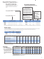
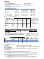
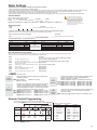
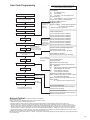
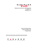
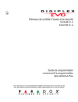
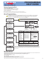
PROGRAMMING
HELP GUIDE
DIGIPLEX EVO48-192
Entering Programming Mode
1) Press and hold the [0] key
2) Enter your [Installer Code] (default-000000)
3) Enter 4-digit [section] you wish to program
4) Enter required data
While in a Section one can press CLEAR and you will move one step back in programming.
You can now Enter any other Section or by pressing CLEAR again you will exit Programming Mode.
Zone Programming Pg.9
Section [0400] is accessible only when using EVO641 and EVO641R keypads. Without section [0400], you can only program the
first 96 zones of the system using sections [0001] to [0096] for the zone’s serial number and input, sections [0101] to [0196] for
zone parameters, sections [0201] to [0296] for report codes and sections [0301] to [0396] for zone labels. In addition, with a
EVO48 panel, you can only program the first 48 zones with or without section [0400].
In any Zone Programming option, pressing [ACC] will save the data and go
to the next zone on the same option screen. Pressing [TRBL] will save the
data and go to the previous zone on the same option screen.
Enter Section [0400], then
enter the number of the
zone you want to program
Zone 1 = 001
Hardwired
Device A
Enter the zone’s 8-digit
serial and 3-digit input
number (The input number
is not needed for module
with only one input)
Press [0] followed by [Enter]
to clear a zone’s serial
number.
Control Panel
SN#:020000A2
Input Terminals
3
4
5
6
8
APR3-ZX8 Module
SN#: 34000041
1
Partition
Select one _____
0 - Disabled (default)
1 - Entry Delay 1
2 - Entry Delay 2
3 - Follow
4 - Instant
5 - 24Hr Buzzer
6 - 24Hr Burglary
7 - 24Hr Hold-up
8 - 24Hr Gas
9 - 24Hr Heat
A - 24Hr Water
B - 24Hr Freeze
C - Delayed 24Hr Fire
D - Standard 24Hr Fire
E - Stay Delay 1
F - Stay Delay 2
2
Input Terminals
3
4
5
6
Zone#
1=
2=
3=
4=
Detector A:
Hardwired Device A:
Hardwired Device B:
Hardwired Device C:
_____
Detector A
SN#: 21000033
COMMUNICATION
CombusNETWORK
7
Hardwired
Device B
Zone Definition
Enter the zone’s label
2
Input 2
1
Enter the zone’s parameters
(01) (*2*4***) default
Enter the zone’s report
codes
(00) (00) (00) (00) default
Keypad
SN#: 1A000252
Keypad Zone
7
Section#
[0001]
[0002]
[0003]
[0004]
Input 5
Hardwired
Device C
Serial#
21000033
1A000252
020000A2
34000041
Input#
N/A
N/A
002
005
8
Zone Option
Select one
12345678
Switch options 1 to 8 ON or OFF
1 - Assigned to Partition 1
(default)
2 - Assigned to Partition 2
3 - Assigned to Partition 3
4 - Assigned to Partition 4
5 - Assigned to Partition 5
6 - Assigned to Partition 6
7 - Assigned to Partition 7
8 - Assigned to Partition 8
[1] Auto Zone Shutdown Enabled
[2] Bypass Enabled (default on)
[3] Stay Zone
[4] Force Zone (default on)
[5]
[6]
Zone Alarm Type
off
off
Steady Alarm
off
on
Pulsed Alarm
on
off
Silent Alarm
on
on
Report Only
[7] Intellizone
[8] Delay before Transmission
.
Alarm Report Code
__ / __
Press [ENTER] to save and
go to the next zone
Pressing [CLEAR] twice will
exit the zone programming
menus. Press [ENTER]
before pressing clear to
save your modifications.
Alarm Restore
Report Code
__ / __
Tamper Report
Code
__ / __
Tamper Restore
Report Code
__ / __
Ademco slow, Silent Knight fast, SESCOA, Ademco express or Pager formats:
Key-in desired 2-digit hex value FF for Contact ID (MEM-Key on LCD) .
Automatic Report Code Programming Pg. 50
Remember that the EVO panel does not have zones, but inputs. These inputs must be assigned to zones first.
Example: The main panel has eight inputs. If you want zones 1 to 8 to be on the main panel you need to fill in the
serial number of the main panel and input next to the zone assignment. Zones 1 to 8 does not have to be on the
main panel though.
Wireless Zones
Wireless detectors all have a six digit serial number. These serial numbers need to be assigned to a MG-RTX3(tranceiver) as inputs. Each MG-RTX3 have 32
inputs, thus with each MG-RTX3 fitted to an EVO one can install 32 wireless zones (6 x MG-RTX3 = 192 zones).
To assign wireless inputs to a MG-RTX one must enter Module Programming. ( the MG-RTX is a module)
1) Press and hold the [ 0 ] key
2) Enter your installer code (Default = 000000)
3) Enter section 4003
4) Enter the 8-digit MG-RTX serial number. (now you are in the module’s programming)
5) Enter module section 101 for input 001 (to - 132 for input 032)
6) Fill in the 6-digit detector serial -or press the tamper switch on the wireless detector
After the inputs have been created they can be assigned to zones the same as any other input. Now refer back to zone programming.
Pg.1
Keyswitch Programming
Pg.19
Keyswitch numbering
Keyswitch parameters
Section [0501] to [0532] represent keyswitches 1 to 32
respectively. This feature allows you to assign a
keyswitch to an addressable or hardwired detection
device.
Section [0601] to [0632] represent keyswitches 1 to 32
respectively. This feature defines the keyswitch’s partition
assigment and arming method.
Keyswitch
Partition Assignment
0 - Not assigned to a partition (default)
1 - Keyswitch Assignment to Partition 1
2 - Keyswitch Assignment to Partition 2
3 - Keyswitch Assignment to Partition 3
4 - Keyswitch Assignment to Partition 4
5 - Keyswitch Assignment to Partition 5
6 - Keyswitch Assignment to Partition 6
7 - Keyswitch Assignment to Partition 7
8 - Keyswitch Assignment to Partition 8
Enter 3- digit [INPUT NUMBER] of Module
to which keyswitch is connected.
Keyswitch Options
(default: all Off)
[ 3 ] - Disarm Only
[ 4 ] - Off = Disarm
On = Disarm only if Stay/
Instant armed
[ 5 ] - Arm Only
[ 6 ] - * Stay Arming
[ 7 ] - * Force Arming
[ 8 ] - * Instant Arming
* Select only one. If all Off’
Keyswitch will regular arm
Keyswitch Definitions
Enter 8- digit [SERIAL NUMBER] of Module
to which keyswitch is connected.
Section
0 - Disabled (default)
1 - Momentary Keyswitch (pulsed)
2 - Maintained Keyswitch (latched)
3 - Generates a Utility Event Event on Open
4 - Generates a Utility Event Event on Open
and Close
8-digit Serial Number
[0501]
___/___/___/___/___/___/___/___
___/___/___
Section
[0601]
[0502]
___/___/___/___/___/___/___/___
___/___/___
[0602]
___/___/___
[0603]
[0503]
Input#
___/___/___/___/___/___/___/___
Define
Assign
___
___
___
___
___
___
Keyswitch Options
3 4 5 6 7 8
3 4 5 6 7 8
3 4 5 6 7 8
Section (3035) will automatically fill in the report codes for Keyswitch Arm/Disarm or they could be filled in individually at sections (0701) to (0832).Pg.20
Panic Input
The above mentioned KEYSWITCH inputs may be programmed as a Panic, Medical or Fire input. These inputs will follow the Auxiliary Panic inputs enabled as
shown below. After assigning a input in any position at section (0501) to (0532) the Panics are defined at sections (0601) to (0632) as follow:
Example: Section (0601) First Digit (5) Second Digit (1) Then enable Options 1 to 8
Section
5-Always
[0601]
[0602]
___
___
1-Panic
2-Medical
3-Fire
___
___
Select Partition
Assignment
12345678
12345678
Partition Panic Alarm Options NB! the below mentioned options must be enabled for the above mentioned input to work on the required partition.
Partition 1
[3123]
Option
[1]
(
= Default Setting)
OFF
ON
Partition 2
[3223]
OFF
Panic 1 (Keys 1 & 3)Panic
ON
Partition 3
[3323]
Partition 4
[3423]
Partition 5
[3523]
Partition 6
[3623]
Partition 7
[3723]
Partition 8
[3823]
OFF
OFF
OFF
OFF
OFF
OFF
ON
ON
ON
ON
ON
ON
[2]
Panic 2 (Keys 4 & 6)Medical
[3]
Panic 3 (Keys 7 & 9)Fire
[4]
Panic 1 Alarm Type
(OFF = Report Only; ON = Audible Alarm)
[5]
Panic 2 Alarm Type
(OFF = Report Only; ON = Audible Alarm)
[6]
Panic 3 Alarm Type
(OFF = Report Only; ON = Fire Alarm)
[7]
Always Report Disarming (OFF = Always;
[8]
Auto-Force on Regular Arming
ON = Only After Alarm)
Remember to fill in the Special Reporting codes for reporting in sections (3930) to (3932). PGM Activation for Radio could be achieved
with PGM Event group 030 (pg.24).
Common Partition Timers Pg.43
Timings
1)
2)
3)
4)
Description
Decimal Values from 000 to 255
Press and hold the [0] key.
Enter your INSTALLER CODE
Exit Delay Timer
Enter the Timer SECTION NUMBER. (Data x 1 second; Default = 060 seconds)
Fill in desired 3 digit timer. Example
Entry Delay 1
030 for 30 seconds. When you fill in
(Data x 1 second; Default = 030 seconds)
the last digit the time will be saved
Entry Delay 2
(Data x 1 second; Default = 060 seconds)
and the programming will move onto
Bell Cut-off Timer
the next section or ask you to fill in a
(Data x 1 minute; Default = 4 minutes)
new section. One does not have to
Special Arming Exit Delay
press ENTER after a time has been
(Keyswitch,auto arming,Winload etc.)
filled in.
Partition 1
Partition 2 Partition 3 Partition 4 Partition 5 Partition 6 Partition 7 Partition 8
Section Section Section Section Section Section Section
Section
Data
[3108]
__/__/__
[3208]
[3308]
[3408]
[3508]
[3111]
__/__/__
[3211]
[3311]
[3411]
[3511]
[3611]
[3711]
[3811]
[3712]
[3812]
[3608]
[3708]
[3808]
[3112]
__/__/__
[3212]
[3312]
[3412]
[3512]
[3612]
[3113]
__/__/__
[3213]
[3313]
[3413]
[3513]
[3613]
[3713]
[3813]
[3130]
__/__/__
[3230]
[3330]
[3430]
[3530]
[3630]
[3730]
[3830]
Dialer Timers Pg.39
Auto-Arm Times Pg. 42
No Movement Auto Arming Schedule Pg. 47
Pg.2
Options
1)
2)
3)
4)
Press and hold the [0] key.
Enter your INSTALLER CODE (Default: 000000)
Enter the Option SECTION NUMBER.
Turn desired Options 1 to 8 ON or OFF by pressing on that digit.
The corresponding number will lite up on the Keypad. To Disable an
Option press on a lit digit.
5) Press the ENTER key.
You will automatically be in the next Section. Change the data or press
CLEAR and enter another Section.
Dialer Options Pg.38
Other Options Pg.38 - 40
Partition Options Pg.43 - 47
Example: System Options Pg.36, 37
SECTION [3031] : Partition Options 1
OFF
= Default setting
SECTION [3032] : Partition Options 2 OFF
ON
Disabled
ON
[1]
Partition 1
[2]
Partition 2
[3]
Partition 3
Disabled Enabled
[3]
Bell/siren output in partition 3
Disabled
Enabled
[4]
Partition 4
Disabled Enabled
[4]
Bell/siren output in partition 4
Disabled
Enabled
Enabled
[1]
Bell/siren output in partition 1
Disabled
Enabled
Disabled Enabled
[2]
Bell/siren output in partition 2
Disabled
Enabled
[5]
Partition 5 (EVO192 only)
Disabled Enabled
[5]
Bell/siren output in partition 5
Disabled
Enabled
[6]
Partition 6 (EVO192 only)
Disabled Enabled
[6]
Bell/siren output in partition 6
Disabled
Enabled
[7]
Partition 7 (EVO192 only)
Disabled Enabled
[7]
Bell/siren output in partition 7
Disabled
Enabled
[8]
Partition 8 (EVO192 only)
Disabled Enabled
[8]
Bell/siren output in partition 8
Disabled
Enabled
Programmable Outputs Pg.21
Event Group
PGM Programming
PGM Activation
ON
PGM Deactivation
OFF
Event Group
Section
Zone Bypassed
Zone in Alarm
025
Fire Alarm
Start #
Section
[0910]
0 6 4
__/__/__
[0911]
2 5 5
__/__/__
[0912]
0 0 0
__/__/__
[0913]
0 0 0 PGM1 Arm/Disarm LED( - trigger only)
__/__/__
PGM2
[0920]
0 3 0
__/__/__
[0921]
2 5 5
__/__/__
[0922]
0 0 0
__/__/__
[0923]
PGM3
[0930]
0 2 4
__/__/__
[0931]
2 5 5
__/__/__
[0932]
0 0 0
__/__/__
[0933]
[0943]
0 0 0 PGM2 Radio Panic( - or + trigger )
__/__/__
0
0 0 PGM3 Radio Burglary( - or + trigger )
__/__/__
0
0 0 PGM4 Radio Open/Close( - or + trigger )
__/__/__
__/__/__ PGM5 Onboard Relay
__/__/__ NB! Change Jumper (JP1) position for
+ or - trip for PGMs 2, 3 and4
PGM4
[0940]
0 6 4
__/__/__
[0941]
2 5 5
__/__/__
[0942]
0 0 0
__/__/__
PGM5
[0950]
__/__/__
[0951]
__/__/__
[0952]
__/__/__
[0953]
PGM1
[0914]
__/__/__
[0915]
__/__/__
[0916]
__/__/__
[0917]
PGM2
[0924]
__/__/__
[0925]
__/__/__
[0926]
__/__/__
[0927]
PGM3
[0934]
__/__/__
[0935]
__/__/__
[0936]
__/__/__
[0937]
__/__/__
PGM4
[0944]
__/__/__
[0945]
__/__/__
[0946]
__/__/__
[0947]
__/__/__
PGM5
[0954]
__/__/__
[0955]
__/__/__
[0956]
__/__/__
[0957]
__/__/__
Feature Group
Feature
000
255 = any Zone #
Zone Numbers
Check the PGM Programming list from page 22 to 27
Note! For Panic and Burglary Radio triggers you need PGMs to pulse, thus
PGM 2 and 3 need to follow the PGM Timer and not the Deactivation Event.
Go to sections [0929] and [0939] and turn Option 1 ON for each Section.
Section
PGM1 Delay [0918]
PGM2 Delay [0928]
PGM3 Delay [0938]
PGM4 Delay [0948]
PGM5 Delay [0958]
[2]
End #
001 to 192
001 to 192
001 to 192
Data
__/__/__ ( 001 to 255 x 1 sec./mins.)
0 0 2 ( 001 to 255 x 1 sec./mins.)
__/__/__
__/__/__
0
0 2 ( 001 to 255 x 1 sec./mins.)
__/__/__ ( 001 to 255 x 1 sec./mins.)
__/__/__ ( 001 to 255 x 1 sec./mins.)
(1*******)
PGM1
[0919]
[1]
__/__/__
Start #
001 to 192
001 to 192
001 to 192
PGM Options
Option
The PGMs are not Pre-Programmed
Suggested PGM programming:
End #
Section
PGM1
Event
023
024
Feature Group
Section
(
= Default Setting)
PGM Deactivation After (OFF = Deactivation Event;
PGM2
[0929]
PGM3
[0939]
PGM4
[0949]
PGM5
[0959]
OFF
ON
OFF
ON
OFF
ON
OFF
ON
OFF
ON
Disabled
Enabled
Disabled
Enabled
Disabled
Enabled
Disabled
Enabled
Disabled
Enabled
ON =
PGM Timer)
PGM Base Time (OFF = Seconds;
ON = Minutes)
Other Programming
Setting the Time and Date:
1) Enter the [Master Code] (default-1234)
2) Press the [TBL] key
3) Press the [8] key
4) Enter the Time and Date.
Changing the Installer Code
1) Press and hold the [0] key
2) Enter your [Installer Code] (default-000000)
3) Enter section [1000]
4) Enter the new Installer Code
Usefull Sections
[4000] - Displays the serial numbers of Panel and all Modules connected to the panel, use [ ] and [ ] to scroll.
[4001] - Reset a module’s programming by entering its serial number.
[4002] - Locate/Unlocate a module by entering the serial number the module’s Locate LED will flash.
[4003] - Module Programming Mode, by entering the serial number of a module one can program the module.
[4004] - Module data broadcasting can be done from here. First enter the source module’s serial number then the
other same type and version modules serial number/s. Press [ACC] to start transfer.
[4005] - Quick module scanning will erase any module removed from panel from its memory.
[4006] - Module Scanning that is the same as above, but you can add modules newly connected to the bus.
Installer Function Keys
To access the installer functions, press and hold the [0] key, enter the [INSTALLER CODE], and then press the KEY below:
[STAY ]
Test Report: Sends the “Test Report” report code programmed in section [3902] to the monitoring station.
[FORCE] Call WinLoad Software: Will dial the PC telephone number programmed in section [3010] in order to initiate communication with a computer
using the WinLoad software.
[ARM]
Answer WinLoad Software: Will force the control panel to answer a call made by the Monitoring Station that is using the WinLoad software.
[DISARM] Cancel Communication: Cancels all communication with the WinLoad software or with the Monitoring Station until the next reportable event.
[MEM]
Installer Test Mode: The installer test mode will allow you to perform walk tests where the bell or siren will squawk to indicate opened zones.
Press the [MEM] button again to exit. Partitions cannot be armed if the Installer Test Mode is enabled.
Start Module Scan: The keypad will display the serial number of each module on the combus.
[TRBL]
Combus Voltmeter: To verify if the combus is supply ing sufficient power, press and hold the [0] key, enter the [INSTALLER CODE] and press the
[ACC]
[ACC] button. A reading of 12.3V or lower at the panel’s service ke ypad connector indicates that the voltage is too low. The voltage may drop
during the control panel battery test.
Pg.3
Dialer Settings
To Enable the Panel for telephone reporting you need to do the following:
1) While in Programming Enable Option 3 in Section [3036].
2) Then enter the client’s Account number in Section [3061]. Note to enter the same account number in Sections [3062] to [3068] if more than 1 Partition is used.
3) Enter 5555 in section [3070] to make sure you are using the Contact ID format. Make sure the control room set the client up with the same format.
4) Enter the base telephone number in section [ 3071]. Press ENTER when you get to the last digit.
5) Go to section [4032] and then [4037]. This will fill in all the Zone and Trouble reporting codes. If it is a business, go to section [4033] and [ 4035] as well.
Account Numbers
MSTN = Monitoring Station Telephone Number
Section Data - Hex Value (0000 - FFFF)
Description
Default
__/__/__/__ (if less than 4 digits, press [ENTER])
0000
ACCOUNT NUMBER
[3062] Partition 2 [3063] Partition 3 [3064] Partition 4 [3065] Partition 5 [3066] Partition 6 [3067] Partition 7 [3068] Partition 8
[3061]
Reporting Formats
Section
[3070]
___
___
___
Only the SIA format supports the [0} digit
in its account numbers. Enter the [STAY]=A
digit in its place. When using the SIA Format,
and the Account Number Transmission (see
option [6] in section [3045] on page 37 correspond tothe partition, the control panel only
uses the Partition 1 Account Number programmed in section [3061], but the report code
includes the account number
Description
___ R EPORTING FORMATS FOR TELEPHONE NUMBERS 1 TO 4
0-Ademco slow/1-Silent Knight fast/2-Sescoa/3-Ademco Express/5-Contact ID/6-SIA FSK/7-Pager
Use the same format for each number. Only the pager format can be used with other reporting formats.
Section Data (Press [ENTER] if less than 32 digits)
Description
[3071] __/__/__/__/__/__/__/__/__/__/__/__/__/__/__/__/__/__/__/__/__/__/__/__/__/__/__/__/__/__/__/__MONITORING STATION /PAGER TELEPHONE #1
[3072] Second Base Number [3073] Third Base Number [3074] Fourth Base Number
Special Telephone Number Keys
Function
LCD
Grafica
Function
Clear
[#]
Delete
[FORCE]
[ARM] (press key until desired Delete from cursor to the end
[DISARM] letter/symbol appears) Insert space
[BYP]
Dial 9 for outside line
[STAY ]
*
#
Switch to Tone Dialing (T)
Wait for second dial tone (W)
4-second pause (P)
LCD
Grafica
[CLEAR] Left action key (Clear)
[TRBL]
[ACC]
[MEM]
9+[STAY ]
Automatic Report Code Programming
When using Contact ID or SIA Reporting formats (section [3070] on page 36), default report codes can be programmed automatically. After automatic
defaults are set, they can be changed and the remaining report codes can be set manually.
Section
Description
Resets all the report codes from sections [0201] to [0296], [0701] to [0832],
[2001] to [2199] and [3900] to [3999] to 00.
[0201] to [0296], [0701] to [0832], [2001] to [2199] & [3900] to [3999]
[4030]
ALL REPORT CODES RESET TO 00
[4031]
ALL REPORT CODES RESET TO FF
[4032]
ZONE A LARM/ALARM RESTORE AND ZONE TAMPER/TAMPER [0201] to [0296]
RESTORE REPORT CODES
USER/KEYSWITCH A RMING & DISARMING REPORT CODES [0701] to [0832], and [2001] to [2199]
SPECIAL CODES
[3900] to [3909]
SPECIAL A RMING/DISARMING REPORT CODES
[3910] to [3929]
SPECIAL A LARM REPORT CODES
[3930] to [3939]
TROUBLE & TROUBLE RESTORE REPORT CODES
[3940] to [3999]
[4033]
[4034]
[4035]
[4036]
[4037]
VDMP3 Voice dialer module
1
Enable
Functions
Select the following options to enable voice reporting and
arm/disarm function.
[1] Arm/disarm
(default 1 and 2 ON)
[3090]
[2] Voice reporting
2
Telephone
Numbers
Program up to 8 telephone numbers which will be called in
sequence in the event of an alarm. Telephone numbers
should be programmed in priority sequence as the VDMP3
will start with telephone number 1. For extra key functions,
see Special Telephone Number Keys on page 40.
[3091] [3091] Telephone number 1
[3095] Telephone number 5
to [3092] Telephone number 2
[3096] Telephone number 6
[3098] [3093] Telephone number 3
[3097] Telephone number 7
[3094] Telephone number 4
[3098] Telephone number 8
3
Enable
Numbers
5
Enable
Features
(PGM)
Choose which telephone numbers will be enabled for each
partition in your system. Options [1] to [8] represent
telephone numbers 1 through 8.
(Default: Telephone number 1 is enabled for all partitions.)
[3133] [3133] Partition 1 [1] to [8]
[3533] Partition 5 [1] to [8]
to [3233] Partition 2 [1] to [8]
[3633] Partition 6 [1] to [8]
[3833] [3333] Partition 3 [1] to [8]
[3733] Partition 7 [1] to [8]
[3433] Partition 4 [1] to [8]
[3833] Partition 8 [1] to [8]
Features in this section correspond to utility key PGMs in the
EVO control panel. For more information, see Feature
Activation (PGMs).
[3087] Options [1] to [8] represent features 1 to 8 (default: OFF)
Remote Control Programming
1) First assign the remote to a user in User Code Programming.
2) Go to section [2900] and choose your remote button functions: (18)
Button 1
Button 2
Button 3
Buttons 2+3
MG-REM1
+
MG-REM2
+
Default
(1 B) (C 0)
Regular
Arm
Utility
Key 1
Utility
Key 2
Disabled
(20)
Disarm
Disarm:
cannot be
modified
Choose 1 function for each button
Entry Function
Entry
[0]
Button Disabled [8]
[1]
Regular Arm
[9]
[2]
Stay Arm
A = [stay]
[3]
Instant Arm*
B = [force]
[4]
Force Arm*
C = [arm]
[5]
N/A
D = [disarm]
[6]
N/A
E = [byp]
[7]
N/A
F = [mem]
Function
Panic 1
Panic 2
Panic 3
Utility Key 1
Utility Key 2
Utility Key 3
Utility Key 4
N/A
3) At Section [2940] enter (00).
Pg.4
User Code Programming
Note: Each option is considered ON when the
number appears within the brackets.
User Options
[1]
[2] Master Feature
OFF Disabled
ON
OFF Master - user can program user
access codes only
ON
ON Full Master - user can program user
access codes, options, and assignments
[3] Duress [6]Stay & Instant
Switch Options
[4] Bypass [7]Force
1 to 8 ON or OFF
[5] Arm Only[8] OFF = Access keypad’s partitions
On default all
ON = Access user’s partitions
users can
Regular Arm
* Note: all users can regular arm.
OFF
1 Enter the Master Code (Default:1234)
2
Enter Programming Mode
By Pressing [0) then [ACC]
3
Select User (002 =user 2)
4
Enter Desired User Code (Pin)
5
User Options
Partition Assignment †
Press the [
6
10
11
] Key
Access Card Assignment
User Label
First Brackets: Access Level
Enter Level from 00 to 15 (00 = all doors)
You must ENABLE
option 1 for ACCESS Access Control Options
CONTROL
] Key
Remote Control Assignment
Access Level & Schedule Assignment
Second Brackets: Schedule
Enter number from 00 to 15 (00 = all times)
Access Control User Options
Press the [
9
will not work.
Press [ENTER] here
if you do not need to
] Key program Access Control.
You will move to Step10
Access Level and
Schedule Assignment
Enter Digits
Press the [
8
] Key
User Area Assignment
Press the [
7
[1] User Code has Access to Partition 1
[2] User Code has Access to Partition 2
[3] User Code has Access to Partition 3
[4] User Code has Access to Partition 4
Switch Options
1 to 8 ON or OFF [5] User Code has Access to Partition 5
Make sure that
[6] User Code has Access to Partition 6
the user has a
Partition enabled [7] User Code has Access to Partition 7
or else the code [8] User Code has Access to Partition 8
If no Remote press
[ENTER] for Label or
[CLEAR] for next user
If no Label
press [ENTER]
[1] Access Control
[2] Can Disarm with Access Card
[3] Card with Door Unlocked Period Extension
[4]
[5]Feature
off
offCannot Arm with Card (armingdisabled)
on
offCan Regular Arm with Card
off
onCan Stay Arm with Card
on
onCan Force Arm with Card
[6] Add Tolerance Window to Schedules
[7] off = Code can arm, disarm & access anytime
on = Code follows Schedule
[8] off = Valid Card can be granted access and
disarm partition
on = Valid Card can be granted access,
Access Card Assignment
Press [ ENTER] to advanced to
save and advanced to next user
Enter Access Card's serial number manually or
present Card to the reader.
Remote Control Assignment*
Enter remote control’s serial number manually or
press a remote button twice.
Access Control (For ACCESS modules and READERS)
Programming Overview:
Steps 1, 2 and 6 are the MINIMUM requirement to program Access Control:
1. Enable Access Control in section [3038] option [1].
2. Assign the Doors in sections [2201] to [2232] by entering the DGP-ACM12 or access keypad’s serial number for each door.
3. Optional: Create up to 15 Access Levels in sections [2601] to [2615]. Assign certain combinations of doors to a level or levels 01 to 15.
These Access Levels could then be assigned to Users in User Code Programming( Step 7: Default = 00 = User have access to all doors).
4. Optional: Create up to 32 Access Schedules in sections [2401] to [2432]. Assign different time periods for access next to each schedule.
These schedules could then be assigned to Users in the User Code Programming( Step 7: Default = 00 = User have access at all times).
5. Optional: Enter Holidays in sections [2710] to [2712], which will disallow access o those days unless (H) is selected next to the user’s Level.
6. Program the User Codes( Pg.12 User manual or above in this guide steps 7 to 9).
NB! The Access module is set to Partition 1 on default. To change this enter Module Programming (section [4003] Pg.3 in this guide) and change
this in section [001] .
Pg.5