1
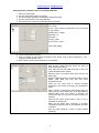
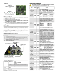
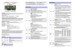
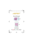
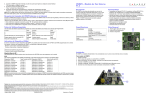
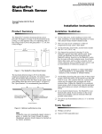
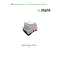
GPRS/CSD/SMS security module GT7 User manual Module version 1.26 Save a tree...please don't print this document unless you really need to www.orvos.ee / [email protected] Security module GT7 transfers security control panel data to monitoring station via GSM network. - Primary alarm transmission channel to monitoring station: either GPRS or CSD or SMS. - Back-up alarm transmission channel to monitoring station: either GPRS or CSD or SMS. - Signal strength and operating failure display. - Alarm transmission to monitoring station by 2 IP addresses and 2 GSM modem phone numbers. - Alarm transmission to up to 4 mobile phones by text SMS. - Remote configuration by GPRS connection is possible. - Remote uploading/downloading of firmware by GPRS connection is fully supported. - Multilingual configuration software. - Simple installation by 4-wire serial connection. Principles of operation Communicator GT7 receives data from: - Common bus: ® Compatible with: DSC PC585, PC1565, PC5020, PC1616, PC1832, PC1864. ® PYRONIX MATRIX 424, MATRIX 832, MATRIX 832+, MATRIX 6, MATRIX 816. ® GE CADDX NX-4, NX-6, NX-8. - Serial output: ® Compatible with: PARADOX SPECTRA SP5500, SP6000, SP7000, 1727, 1728, 1738. ® PARADOX MAGELLAN MG5000, MG5050. ® PARADOX DIGIPLEX EVO48, EVO192, NE96, EVO96. ® PARADOX ESPRIT E55, 728ULT, 738ULT. - Telephonic communicator i.e. control panel transfers data to GT7 communicator through C11 interface. - Outputs (PGMs), i.e. communicator transfers signal regarding the change of input state, having received it through input expander CZ6. Security module GT7 sends information, received from the control panel, to monitoring station by either GPRS or CSD or SMS. If the connection has failed, communicator will repeatedly attempt to restore it for n times (number of attempts (n) can be set). If the module GT7 fails to restore connection, the module will automatically connect to the back-up channel and send the unsent messages through it. Duration of connection or attempts to connect to the back-up channel can be set, after which the communicator tries again to connect to the primary channel. Security module GT7 sends signals PING for testing of communication. Messages sent to monitoring station correspond to Contact ID table of codes. Message receivers: Software based IP receiver AGSR (Alarm GSM Signals Receiver). Free AGSR receiver software available to operate with practically any central station software. This software is designed to convert data received via GPRS to serial RS232 or Ethernet TCP/IP . The software emulates Surgard MLR2DG. This is free software and available with purchase of GT7 module. Please contact us at [email protected] Hardware based receiver Linux AGSR10. Module can transform the data, received from the security panel, to text SMS messages and send them to up to 4 mobile phones. Text of SMS message (name of object, user names, partitions names, event descriptions) can be specified by the User. Package content - Security module GT7, (the SIM card is not included) - GSM straight antenna, - 2 fittings DIN 7985 M3x6, - Velcro type stick-on (two-sided x10 cm). Specifications Power supply Current Frequency Primary reporting channel to CMS DC 12 V up to 60 mA (stand-by running) up to 500 mA (by alarm transmitting) 850/900/1800/1900 MHz either GPRS or CSD or SMS 1 www.orvos.ee / [email protected] Back-up reporting channel to CMS Alarm transmission to 4 mobile phones Storage Input Output Operating environment Dimensions either GPRS or CSD or SMS by text SMS up to 60 messages 1, NC type 1, OC type, switching 30V DC and 100 mA from -10ºC to 50ºC, relative air humidity 80% when +20ºC 85 x 65 x 25 mm Description of the communicator GT7 GSM antenna connector LED indicators, Terminal block SIM card holder USB socket Description of terminals block Clamp +E Com Clock Data IN OUT Meaning +12V supply clamp Common (device ground) clamp Synchronizing signal clamp Data signal clamp Input clamp (NC type) Output clamp (OC type) Operation of light indication LED1 OFF Yellow ON Yellow flashing Yellow ON Yellow ON Green ON Green ON LED2 Red flashing OFF OFF Red ON Green ON Green ON Red and green flashes by arrangement Meaning No SIM card Configuration mode Registering to GSM network Communication has failed Data transmitting mode Stand-by Number of red flashes indicates GSM signal level Fitting to control panel’s case 1. Set operation parameters. 2. Put activated SIM card into a holder as shown in the picture. see chapter “Module configuration ” Note: 1. Ask your GSM provider about SIM card properties before transferring data via chosen channel. 2. Disable PIN code request if necessary. 2 www.orvos.ee / [email protected] 3. Fit to control panel’s case. Drill holes on control panel’s case. 4. Screw on the GSM antenna. 5. Connect wires to control panel. 6. Switch on power supply. 7. According to LED indications, check GSM signal level. Test data transmission. See wiring diagrams Note: If GSM signal level is not sufficient, connect other type antenna. Wiring diagrams Wiring diagram to DSC® Compatible with: PC1616, PC585, PC1565, PC5020. PC1832, PC1864 Wiring diagram to Pyronix ® Compatible with: MATRIX 424, MATRIX 832, MATRIX 832+, MATRIX 6, MATRIX 816. Wiring diagram to Paradox ® Compatible with: SPECTRA SP5500, SP6000, SP7000, 1727, 1728, 1738, MAGELLAN MG5000, MG5050, DIGIPLEX EVO48, EVO192, EVO96, NE96, ESPRIT E55, 728ULT, 738ULT. Wiring diagram to Caddx ® Compatible with: NX-4, NX-6, NX-8. Module configuration Operational parameters can be set, read, modified and updated by using configuration software ConfigGT7. Configuration is possible by two methods: when communicator GT7 is connected to PC on-site using USB cable and when communicator GT7 is remotely connected to IP receiver AGSR by GPRS connection. 3 www.orvos.ee / [email protected] Configuration software ConfigGT7 installation. Download file ConfigGT7_setup.exe www.orvos.ee and follow the installation wizard. USB driver installation. Microchip® USB drivers mchpcdc.inf are required for module GT7 ® connection to PC. If Microchip USB drivers have never been installed to PC before, Windows Hardware Wizard window will appear. To finish the installation choose “Yes, this time only”, click and follow the installation wizard. 4 from USB New Next www.orvos.ee / [email protected] Setting operation parameters when connecting by USB cable 1. 2. 3. 4. 5. Switch on power supply. Run the configuration software ConfigGT7. Choose the dialog language in window Main/Settings/Language. Connect communicator to PC using USB cable. Set parameters of comport in window Main/Settings/Comport. [Name] – write name of comport, if it’s necessary (eg. GT7_USB). [Port] – select comport communicator GT7 is connected to (eg. COM2). [Baudot rate] – 115200. [Data bits] – 8. [Stop bit] – 1. [Parity] – None. [Flow control] – None. Click button [Apply]. 6. Click icon [Connect/Disconnect]. 7. Click icon [Read] to read existing parameters. Enter access code to allow configuration in the appeared window (default 1234). 8. Enter common communicator parameters in window Main. Enter account number [Account]. Check box [Hex], to allow hexadecimal entering. Enter SIM card PIN code [SIM Card PIN]. If PIN code request is disabled, leave it blank. Select the type of connected control panel from the list [Panel type]. Select a PING transmission to monitoring station channel [GPRS, CSD, SMS ping time] and enter PING transmission period. Check the box [Test time] to activate message transmission Test function and specify the transmission period. Enter a number of attempts the communicator will try to restore primary communication after it has failed [Backup reporting after]. After this number of attempts, the communicator will try to connect to a back-up channel for reporting. Check the box [Save access code] in order for PC to remember the access code. When the box [Read after connection] is checked, configuration parameters will be automatically read after connection. Click the button [Restore] in order to restore default parameters. 5 www.orvos.ee / [email protected] 9. Select primary and back-up data transmission channel in window Reporting/GPRS&GSM reporting and set parameters of network and receivers. Select primary data transmission channel [Primary reporting]. Select back-up data transmission channel [Backup reporting]. In active fields: Enter receiver IP address [Server IP address or Domain]. Enter the receiver port [Port]. Enter GSM modem SIM card number [Tel]. Order: country code (without +), network operator’s code, local number. Enter access point name [APN]. Fill fields [User Name], [Password], [DNS1] and [DNS2] by request of service provider or leave them blank. Select transmission protocol from the list [Protocol]. Enter a 6-digit data encryption code [Encryption key]. Note: this key has to be the same as entered into IP receiver. Enter a duration of connection to the back-up channel [Return to primary after]. When this time has expired, communicator starts to restore connection to primary channel. To modify and activate communicator generated messages (list [Special event codes]), open the window by double clicking on selected event’s row and fill the appeared window. 10. Enter 4 phone numbers by which monitoring station will be able to activate GPRS connection between communicator and IP receiver for configuration. Fill fields Settings/CMS Phones. Enter up to 4 phone numbers [T01], [T02], [T03], [T04]. Sending a specified form SMS message from a phone, which number is in this list, allows activation of GPRS connection between communicator and IP receiver. If fields are left blank, this allows activation of GPRS connection by sending SMS out of every mobile phone. Order: country code (without +), network operator’s code, local number. 6 www.orvos.ee / [email protected] 11. Specify distribution of the reports by type and user groups for the communicator to transfer control panel data to mobile phone by SMS in specific order. Fill the window Reporting/Text SMS reporting. Specify distribution of messages by type and phone numbers, i.e. to whom the what type of messages should be transferred. Check the table [Name] Enter phone numbers [T1], [T2], [T3] and [T4]. Order: country code (without +), network operator’s code, local number. Enter object name [Account] (this true name will be shown in the SMS message text when it is received). Fill the list [Partitions] to start create texts of SMS messages transferred. It’s possible to change texts written in [Area1, …, Area16] (these true names will be shown in SMS message text when it is received). If partitions are not created, leave the list blank. 12. Fill lists in window Reporting/Users&Zones to create SMS message texts transferred to mobile phone. Enter user names by access codes who will have possibility to arm/disarm the security system [User1, …, User16] (these true names will be shown in SMS message text when it is received). Enter names of security zones [Zone1, …, Zone16] (these true names will be shown in SMS message text when it is received). 13. Click icon [Write] or function key [F6] to enter the set parameters into communicator’s memory. 14. Click icon [Save] or function key [F5] to save the set parameters to file with extension “.gst”. 15. Click icon [Disconnect] or function key [F8] to disconnect from the communicator GT7. Click icon [Open] or function key [F3] to open a saved configuration file. Click icon [F4] or function key [F4] to open the last saved configuration file. Setting operation parameters remotely when connected by GPRS connection Remote configuration can be done by using software ConfigGT7, when there is an active GPRS connection between IP receiver AGSR and the communicator GT7. Send an SMS message in appropriate form to activate GPRS connection. Communicator will only respond to SMS messages if it receives a message from a phone whose number is entered into Main/Settings/CMS Phones list. If the above discussed list is blank, communicator will respond to SMS in an appropriate form from any mobile phone. When GT7 receives this message, it initialises the GPRS connection with IP receiver AGSR. 7 www.orvos.ee / [email protected] SMS structure: CONNECT space1234spaceSERVER=100.100.100.100spacePORT=1000s pace APN=providerspaceUSR=userspace PSW=psw space ENCR=enc Description: - write the initial command (word “CONNECT”), - write the 4-digit configuration access code (default 1234), - write the word “SERVER=” and receiver IP address from which the configuration will be done (instead of symbols “100.100.100.100” written in example) - write the word “PORT=” and port of receiver from which the configuration will be done (instead of “1000”), - write the word “APN=” and access point name (APN) (instead of “provider”), - write the word “USR=” and APN User name if required by the provider (instead of “user”), - write the word “PSW=” and APN Password, if required by the provider (instead of “psw”), - write the word “ENCR=” and 6-digit data encryption code (default 123456) (instead of “enc”). Notes: 1. The word space means space interval between symbols. 2. If provider does not require APN User name and Password, text “…spaceUSR=spacePSW=space…” have to be written accordingly in the SMS message. Actions after the SMS has been sent: 1. Open the main window of IP receiver AGSR and select the row of communicator which parameters will be set. 2. Run configuration software ConfigGT7 by right-clicking on the appeared icon [ConfigGT7]. 3. Click icon [Connect] in the tool bar when the ConfigGT7 window will appear. Word Connected/ Disconnected indicates the state of GPRS connection. 4. Configuration procedure is the same as when communicator is connected to PC on-site using USB cable. Filling fields and selecting parameters is necessary. 8