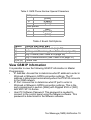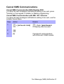
1
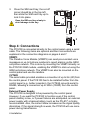
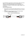
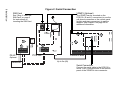
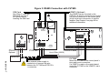
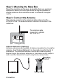
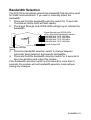
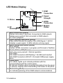
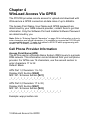
GSM Communicator Module PCS100 V1.1 Installation and User Manual Warranty Paradox Security Systems Ltd. (“Seller”) warrants its products to be free from defects in materials and workmanship under normal use for a period of one year. Except as specifically stated herein, all express or implied warranties whatsoever, statutory or otherwise, including without limitation, any implied warranty of merchantability and fitness for a particular purpose, are expressly excluded. Because Seller does not install or connect the products and because the products may be used in conjunction with products not manufactured by Seller, Seller cannot guarantee the performance of the security system and shall not be responsible for circumstances resulting from the product’s inability to operate. Seller obligation and liability under this warranty is expressly limited to repairing or replacing, at Seller's option, any product not meeting the specifications. Returns must include proof of purchase and be within the warranty period. In no event shall the Seller be liable to the buyer or any other person for any loss or damages whether direct or indirect or consequential or incidental, including without limitation, any damages for lost profits stolen goods, or claims by any other party, caused by defective goods or otherwise arising from the improper, incorrect or otherwise faulty installation or use of the merchandise sold. Notwithstanding the preceding paragraph, the Seller’s maximum liability will be strictly limited to the purchase price of the defective product. Your use of this product signifies your acceptance of this warranty. BEWARE: Dealers, installers and/or others selling the product are not authorized to modify this warranty or make additional warranties that are binding on the Seller. Patents One or more of the following US patents may apply: 7046142, 6215399, 6111256, 6104319, 5920259, 5886632, 5721542, 5287111, 5119069, 5077549 and RE39406. Canadian and international patents may also apply. © 2009 Paradox Security Systems Ltd. All rights reserved. Specifications may change without prior notice. Digiplex EVO, Magellan, Spectra and Esprit are trademarks or registered trademarks of Paradox Security Systems Ltd. or its affiliates in Canada, the United States and/or other countries. For the latest information on products approvals, such as UL and CE, please visit www.paradox.com. INCLUDED ITEMS • • • • GSM Communicator Module (PCS100) Metal box Antenna Serial cable IMPORTANT BEFORE STARTING • Requires active SIM Card (sold by your GSM cell phone provider) OPTIONAL ACCESSORIES Plug-In Voice Module (VDMP3): The PCS100 supports the use of the Paradox Voice Module (VDMP3) to send pre-recorded voice messages to report alarms as well as control the system via voice-guided menus. This is done by mounting the VDMP3 directly on the PCS100 GSM module, enabling the VDMP3 to dial out using the GSM cell phone network. Refer to page 6 and page 7 for VDMP3 connection information. Plug-In RS485 Converter (CVT485): The serial cable provided enables a connection of up to 2m (6ft) from the control panel. If the PCS100 has to be installed further from the control panel (for better reception, to conceal the PCS100, etc.), the CVT485 converts serial to RS485, allowing a connection of up to 300m (1000ft) from the control panel. Refer to page 7 for CVT485 connection information. Antenna Extension: An antenna extension can be used if the reception at the PCS100 installation location is not satisfactory. The use of antenna extensions greater than 7m (24ft) can cause a loss of signal quality between the antenna and the PCS100 module. Signal loss is proportionate to the length of the antenna extension. Try to locate the best antenna location while using the shortest possible extension to avoid losing signal quality. Refer to page 8 for antenna connection information. The following is a list of available antenna extensions. EXT2: 2m(6ft) EXT15: 14.5m(48ft) EXT4: 4m(12ft) EXT 18: 18m(60ft) EXT7: 7m(24ft) 12 Vdc External Power Supply: The PCS100 is designed to be powered by the control panel. However, if you want the PCS100 to function even if the control panel’s battery is low, or if power failures are anticipated, an external power supply with a backup battery (such as the PS-817, sold separately) is highly recommended. Also, the current draw increases as the signal quality diminishes. If the signal strength is weak, the PCS100 will use more power during transmission. Refer to page 6 for power supply connection information. Table of Contents Chapter 1: Product Overview...................................................................................2 Technical Specifications .......................................................................................... 3 Chapter 2: Installation ..............................................................................................4 Step 1: Preparing the Installation............................................................................. 4 Step 2: Disabling the SIM Card PIN ........................................................................ 4 Step 3: Insert the SIM Card ..................................................................................... 4 Step 4: Connections ................................................................................................ 5 Step 5: Mounting the Metal Box............................................................................... 9 Step 6: Connect the Antenna................................................................................... 9 Bandwidth Selection .............................................................................................. 10 LED Status Display................................................................................................ 11 Chapter 3: GSM Reporting .....................................................................................12 Additional Sections ................................................................................................ 12 Chapter 4: WinLoad Access Via GPRS .................................................................13 Cell Phone Provider Information............................................................................ 13 Site Specific Information ........................................................................................ 15 Remote Upload/Download via GPRS .................................................................... 16 Chapter 5: Text Message (SMS) Notification........................................................17 Text Message Language ....................................................................................... 18 End User SMS Programming ................................................................................ 19 View GSM IP Information ...................................................................................... 20 Cancel SMS Communications ............................................................................... 22 Chapter 6: Arm / Disarm System with Text Messages ........................................23 Text Message Commands Format ........................................................................ 23 Chapter 7: Supervision Options ............................................................................25 GSM No Service Trouble Options ......................................................................... 25 GSM RF Jamming Supervision ............................................................................. 26 Control Panel Supervision ..................................................................................... 26 Chapter 8: Using the VDMP3 (Optional) ...............................................................27 VDMP3 Programming............................................................................................ 27 Chapter 9: Upgrading the Firmware ......................................................................28 Appendix: SMS Messages Information ............................................................... 29 Event Groups......................................................................................................... 29 List of SMS Phone Numbers ................................................................................. 33 Installer Programming............................................................................................ 34 Entering Special Characters .................................................................................. 35 Chapter 1 Product Overview The PCS100 GSM module provides Paradox control panels with wireless communication capabilities through a GSM (cell phone) network to report system events to a monitoring station, to remotely upload/download with WinLoad software via GPRS, to send text messages (SMS) of system events to cell phones, and to send prerecorded voice messages (VDMP3) to any phone as well as access the system with voice-guided menus via GSM. All of this is achieved through proprietary communication via simple 4-wire serial connection between the control panel and the PCS100 module. • Upload/Download via GPRS: The PCS100 provides fast upload/download via a GPRS connection. GPRS allows internet communications through a GSM (cell phone) network at data rates of up to 48Kbit/s. See Chapter 4 on page 12. • Report via GSM: Report control panel events to the monitoring station via a GSM (cell phone) network using any control panel reporting format. The PCS100 can be set as the primary dialer, backup dialer, or as both. See Chapter 3 on page 11. • Report via text messages (SMS): Select which event groups will send SMS messages to up to 8 or 16 cell phones. Each text message contains a detailed description of the event including site name, date, time and any associated labels, such as area, zone and serial number. The description of each system event is pre-defined in the PCS100 module and is available in multiple languages (installer selectable). See Chapter 5 on page 16. • Arm/disarm (SMS): End users can arm or disarm the system by sending a text message (SMS) to the PCS100. See Chapter 6 on page 22. • Voice reporting: The PCS100 supports the use of the Paradox Plug-In Voice Module (VDMP3) to send pre-recorded voice messages to up to 8 phone numbers to report alarms. The VDMP3 is plugged directly on the PCS100. When the VDMP3 is present, the end user can also arm/disarm, request system status and control PGMs using a voice-guided menu. See Chapter 8 on page 26. Product Overview 1 • Control panel communication supervision: The PCS100 will report to the monitoring station should there be a loss of communication with the control panel. See Chapter 7 on page 24. • GSM RF jamming detection: When detected, the control panel will generate a trouble as well as report it to the monitoring station through a landline. See Chapter 7 on page 24. • In-field upgradeable: The PCS100 is in-field firmware upgradeable. See Chapter 9 on page 27. • Simple installation: The PCS100 can be installed with a simple 4-wire serial connection up to 2m (8ft) from the panel, or up to 300m (1000ft) from the control panel using an optional Plug-In RS-485 Converter (CVT485). The module antenna can be installed up to 18m (60ft) from the module using optional antenna cable extensions depending on the local signal strength. See Chapter 2 on page 3. Technical Specifications Compatibility See the paradox.com website for updated information Output power Antenna bandwidth: Antenna Power input EVO48 and EVO192 control panels V1.4 with EVO641 and EVO641R keypads V1.4 or higher MG Series and Spectra SP control panels V3.0 with K32LCD keypads V1.1 or higher. E55 control panels V2.0, E65 control panels V2.1 It is possible to program the PCS100 with any keypad compatible with Magellan, Spectra SP or /E55/E65 control panels. However, to enter text without a K32LCD, use WinLoad. Class 4 (2W) @ 850 / 900 MHz Class 2 (1W) @ 1800 / 1900 MHz 70 / 80 / 140 / 170 MHz Automatic band detection (refer to page 9) Gain < 3dBi; impedance 50 ohm; input power > 2W peak power 12Vdc (from control panel or external power supply, see page 4 for additional information) 60mA standby (max. 600mA during transmission) Current consumption Dimensions 18cm x 13.5cm x 4cm (7in x 5.25in x 1.6in) Operating 0 to 50°C (32 to 122°F) temperature Data encryption 128-bit (MD5 and RC4) or 256-bit (AES) SMS protocol 8-bit or 16-bit 2 Product Overview Chapter 2 Installation This chapter details the basic hardware installation steps. Step 1 Step 2 Step 3 Step 4 Step 5 Step 6 Chapter 3 Chapter 4 Chapter 5 Preparing the Installation Disabling the SIM Card PIN Inserting the SIM Card Connecting the Module Mounting the Metal Box Connecting the Antenna Setting Up GSM Reporting Setting Up GPRS Connection Setting Up SMS Notifications page 3 page 3 page 3 page 4 page 8 page 8 page 11 page 12 page 16 Step 1: Preparing the Installation Open the metal box the remove the screws holding the PCB in place to facilitate wire connection. Step 2: Disabling the SIM Card PIN Prior to setting up your PCS100, it is important that the Personal Identification Number (PIN) of the SIM card be disabled. In order to disable the PIN number, you will require a standard cellular phone. For more information on how to disable the PIN number, please consult your cellular phone’s manual. Step 3: Insert the SIM Card The SIM card contains all information concerning your cell phone account. It is sold by cell phone providers that support GSM. 1. 2. Slide the SIM card tray towards the bottom of the board to unlock it. Flip the SIM card tray open then insert the SIM card in the tray with the cut-off corner at the bottom left. Installation 3 3. Close the SIM card tray; the cut-off corner should be in the top left, then slide the SIM card tray up to lock it into place. Open the SIM card tray slowly to avoid damage to the tray. 1 IN-FIELD PROGRAM J3 J2 + - A+ B12 VDC RS485 SERIAL (UART) 2 3 Step 4: Connections The PCS100 is connected directly to the control panel using a serial cable. The following items are optional and their connections are explained in the connection diagrams on pages 6 and 7. VDMP3 The Paradox Voice Module (VDMP3) can send pre-recorded voice messages on up to 8 phone numbers to report alarms via the GSM cell phone network. This is done by mounting the VDMP3 directly on the PCS100 GSM module, enabling the VDMP3 to dial out using the GSM cell phone network. The VDMP3 can also be mounted on the control panel and use the landline. CVT485 The serial cable provided enables a connection of up to 2m (6ft) from the control panel. If the PCS100 has to be installed further from the control panel (e.g., better reception), the CVT485 converts serial to RS485, allowing a connection up to 300m (1000ft) from the control panel. External Power Supply The PCS100 is designed to be powered by the control panel. However, if you want the PCS100 to function even if the control panel’s battery is low, or if power failures are anticipated, an external power supply with a backup battery (such as the PS-817) is highly recommended. Also, the current draw increases as the signal quality diminishes. If the signal strength is weak, the PCS100 will use more power during transmission. 4 Installation If your PCS100 is powered by an external power supply such as the PS817, the serial cable’s wires need to be modified prior to connection onto the PCS100 Module and the control panel. This modification is necessary to maintain proper voltage readings on the control panel. Serial Cable Modifications 1. 2. Ensure that one end of the serial cable’s white wire is cut prior to connecting it to the PCS100’s Serial UART connector, as shown below. Connect the other end directly to the control panel’s Serial connector or VDMP3’s EBUS connector. Figure 1: Serial Cable Modifications Cut White Wire White Green Black Red White Green Black Red Installation 5 SIM Card VDMP3 (Optional) See “Step 3: Insert the SIM Card” on page 3 for instructions on inserting the SIM Card. The VDMP3 can be mounted on the PCS100 (J2 and J3 connectors) to use the cell phone connection or the control panel (DIALER and EBUS connectors) to use the landline. See Chapter 8 on page 26 for additional information. IN-FIELD PROGRAM J3 J2 DIALER EBUS 6 Installation Figure 2: Serial Connection Batt. AC AC + - TST PS-817 Optional Transformer + - A+ B12 VDC RS485 SERIAL (UART) PCS100 Control Panel Up to 2m (6ft) Serial Connection Connect the serial cable to the PCS100’s SERIAL (UART) connector and to the control panel or the VDMP3’s EBUS connector. Figure 3: RS485 Connection with CVT485 SIM Card VDMP3 (Optional) See “Step 3: Insert the SIM Card” on page 3 for instructions on inserting the SIM Card. The VDMP3 can be mounted on the PCS100 (J2 and J3 connectors) to use the cell phone connection or the control panel (DIALER and EBUS connectors) to use the landline. See Chapter 8 on page 26 for additional information. IN-FIELD PROGRAM J3 J2 Batt. + + - A+ B12 VDC RS485 AC AC + - TST PS-817 Optional PCS100 - A+ B- SERIAL (UART) Control Panel Up to 300m (1000ft) Transformer CVT485 Installation 7 If an external power supply is needed do not connect the wire between the CVT485 and PCS100’s + connectors. Mount the CVT485 on the control panel’s EBUS and DIALER connectors. If a VDMP3 is used on the control panel, mount the CVT485 on the VDMP3’s EBUS connector. Step 5: Mounting the Metal Box Mount the metal box as far away as possible from any electronic equipment, above the control panel and as high as possible to ensure protection from interference and to maximize the signal quality. Step 6: Connect the Antenna The antenna connects to the antenna cable soldered on the PCS100’s PCB. The antenna cable’s connector is outside of the metal box. The antenna cable connector is outside the metal box IN-FIELD PROGRAM J3 J2 Antenna Extension (Optional) Antenna extensions are available to improve reception by moving the antenna. See “Optional Materials” on the inside cover for the list of extensions. The antenna extension is sold with a wall mounting bracket. Insert the antenna extension in the bracket until it snaps in and mount the bracket to the wall using the two screw holes. Mounting Bracket Screw Holes 8 Installation Bandwidth Selection The PCS100 automatically detects the bandwidth that has to be used for GSM communications. If you wish to manually select the bandwidth: 1. Press and hold the bandwidth selection switch for 10 seconds. The Module Online LED will flash rapidly. 2. The Signal Strength and GPRS LEDs will light up to indicate the bandwidth. IN-FIELD PROGRAM J3 J2 Signal Strength and GPRS LEDs. All on: Automatic Bandwidth Detection GSM 850 MHz, PCS 1900 MHz GSM 850 MHz, DCS 1800 MHz GSM 900 MHz, PCS 1900 MHz GSM 900 MHz, DCS 1800 MHz Module Online LED Bandwidth Selection Switch 3. Press the bandwidth selection switch to change between automatic band detection and specific bandwidths. 4. Press and hold the bandwidth selection switch for 5 seconds to save the selection and reboot the module. If the bandwidth selection switch is not pressed for more than 5 seconds, the module will exit bandwidth selection mode without saving any changes. Installation 9 LED Status Display 1: GSM Connection IN-FIELD PROGRAM J3 J2 2: Signal Strength 5: Status 3: GPRS Connection 6: RF Jamming + - A+ B12 VDC RS485 SERIAL (UART) 4: Module Online 1 GSM Connection (Green) Flashes once every 3 seconds: Connected to GSM network Flashes every second: Not connected to GSM network On: Call in progress 2 Signal Strength Indicators (Green) These LEDs indicate the quality of the GSM Signal. 1 LED lit indicates a weak signal, 3 LEDs indicate a strong signal. 3 GPRS Connection Status (Green) Off by default Flashes: GPRS connection in progress via WinLoad or NeWare. 4 Module Online LED (Green) Flash once every second = Normal operation Slow Flash: With GSM Connection LED flashing = No SIM card inserted With GSM Connection LED off = On-board GSM power supply failure 5 Status LEDs Error (Red): Lights up to indicate problems with the communications with the control panel RX (Green): Flashes when receiving information from the panel TX (Green): Flashes when transmitting information to the panel 6 RF Jamming (Red) On: Indicates jamming of the GSM network communications 10 Installation Chapter 3 GSM Reporting GSM reporting is the use of the cell phone network to report control panel events to a monitoring station. GSM reporting can be used either as the primary dialer, as a backup dialer, or as the only dialer used. GSM reporting can be done using any reporting format supported by the control panel. This connection also allows the PCS100 to supervise the presence of the control panel and to report the loss of communication with the control panel. To use GSM network reporting, the following PCS100 specific options must be programmed in the compatible control panel. Table 1: Reporting Method Selection Digiplex EVO Section [2950]; options [1] & [2] MG / SP / E-Series Section [805]; options [1] & [2] [1] [2] OFF* OFF* Landline only OFF ON Primary: Landline Backup: GSM ON OFF Primary: GSM Backup: Landline ON ON GSM only * Default value. This is used when no PCS100 is connected to the control panel. Additional Sections The following programming must be entered in the control panel for the PCS100 to report over the GSM network. Refer to your control panel’s programming manual for detailed information. • Enable the dialer • Enter a monitoring station’s phone number(s) • Enter the account number(s) • Select the reporting format • Program the event report codes • Program the event call direction GSM Reporting 11 Chapter 4 WinLoad Access Via GPRS The PCS100 provides remote access for upload and download with WinLoad via a GPRS connection at data rates of up to 48kbit/s. The Access Point Name, User Name and GPRS password are determined by your GSM network provider; contact them to get that information. Only the Software Port and Installer Software Password are determined by you. Note: Refer to “Entering Special Characters” on page 34 for information on how to enter characters and special characters. It is possible to program the PCS100 with any compatible keypad. To enter text without a K32LCD when programming with an MG / SP / E-Series, use WinLoad. Cell Phone Provider Information Access Point Name (APN) The APN is used in a Domain Name System (DNS) query to a private DNS network. This information can be obtained from your cell phone provider. For APNs over 16 characters, use the second section to enter characters 17 to 32. Default: Blank APN Part 1 (Characters 1 to 16) Digiplex EVO Section [2960] MG / SP / E-Series Section [921] _/_/_/_/_/_/_/_/_/_/_/_/_/_/_/_/ APN Part 2 (Characters 17 to 32) Digiplex EVO Section [2961] MG / SP / E-Series Section [922] _/_/_/_/_/_/_/_/_/_/_/_/_/_/_/_/ Example: wap.provider.com 12 WinLoad Access Via GPRS User Name This information can be obtained from your cell phone provider. For user names over 16 characters, use the second section to enter characters 17 to 32. Default: Blank User Name Part 1 (Characters 1 to 16) Digiplex EVO Section [2962] MG / SP / E-Series Section [923] _/_/_/_/_/_/_/_/_/_/_/_/_/_/_/_/ User Name Part 2 (Characters 17 to 32) Digiplex EVO Section [2963] MG / SP / E-Series Section [924] _/_/_/_/_/_/_/_/_/_/_/_/_/_/_/_/ Example: user GPRS Password This information can be obtained from your cell phone provider. For passwords over 16 characters, use the second section to enter characters 17 to 32. Default: Blank Password Part 1 (Characters 1 to 16) Digiplex EVO Section [2964] MG / SP / E-Series Section [925] _/_/_/_/_/_/_/_/_/_/_/_/_/_/_/_/ Password Part 2 (Characters 17 to 32) Digiplex EVO Section [2965] MG / SP / E-Series Section [926] _/_/_/_/_/_/_/_/_/_/_/_/_/_/_/_/ Example: password WinLoad Access Via GPRS 13 Site Specific Information The following information is determined by the installer and is specific to the installation site. Software Port The Software Port must match the port entered in the WinLoad or NEware software’s GPRS Connection Settings for that site’s account. Default: 10000 Port Digiplex EVO Section [2966] MG / SP / E-Series Section [920] _/_/_/_/_ Installer Software Password The Installer Software Password is used to access installer software through TCP/IP and GPRS networks. The password is case sensitive. This password is entered in WinLoad’s GPRS Connection Settings for that site’s account. Default: admin WinLoad TCP/IP/GPRS Password Digiplex EVO Section [3013] MG / SP / E-Series Section [927] _/_/_/_/_/_/_/_/_/_/_/_/_/_/_/_/ 14 WinLoad Access Via GPRS Remote Upload/Download via GPRS In order to connect to the GPRS network (public and private), you must initiate the connection by sending an SMS message to the module. To establish communication with the PCS100 GSM Communicator Module: 1. Launch Winload. 2. Select the account in which you wish to establish communication with. 3. From the menu bar, select System > Wait for Call. The connection Progress window will then be displayed. 4. Enter the SMS text information to be sent to the PCS100 GSM Communicator Module as you see it on screen. e.g., “Padmin.A10.10.1.100.P10001” . SMS Message WinLoad Access Via GPRS 15 Chapter 5 Text Message (SMS) Notification In addition to reporting control panel events via a GSM cell phone network, the PCS100 can also send text messages (SMS) to the end user on up to 16 cell phones. The PCS100 can send text messages for any control panel event due to its proprietary communication through the panel’s serial port. Each text message contains a detailed description of the event including site name, date and time, and any associated labels, such as area, zone and serial number. The detailed description of each system event is pre-programmed and hardcoded into the PCS100 module. Installer Programming: • Select SMS Language • Enter Site Name Master (End-User) Programming: • Set up to 16 cell phone numbers • Assign areas per phone number • Select event group per phone number • View GSM IP information 16 Text Message (SMS) Notification Text Message Language Select the language that will be used by the PCS100 when reporting system events via text message (SMS). See page 16 for details. SMS Language Digiplex EVO Section [2953] MG / SP / E-Series Section [856] _ / _ / _ (000 - 255) Table 2: SMS Language Language English* French Spanish Italian Swedish Polish Portuguese German Value 000 001 002 003 004 005 006 007 Language Turkish Hungarian Czech Dutch Croatian Greek Hebrew Russian Value 008 009 010 011 012 013 014 015 Language Value Bulgarian 016 Romanian 017 Slovak 018 Chinese 019 Serbian 020 * Default value Some languages are not currently supported. If an unsupported language is selected messages will be sent in English. Some languages, like Hungarian or Romanian, will generate 2 SMS messages per event reported and other languages will use special LCD characters not supported on all cell phones. Refer to the paradox.com website for the list of languages that are supported, that generate 2 SMS messages or that use special characters. Site Name The site name will be included in every SMS notifications to indicate at what site the event was generated. (e.g., Paradox Headquarters). Note: Refer to “Entering Special Characters” on page 34 for information on how to enter characters and special characters. It is possible to program the PCS100 with any compatible keypad. To enter text without a K32LCD when programming with an MG / SP / E-Series, use WinLoad. SMS Site Name Digiplex EVO Section [2954] MG / SP / E-Series Section [780] _/_/_/_/_/_/_/_/_/_/_/_/_/_/_/_/ Default: “Your Alarm Site” Text Message (SMS) Notification 17 End User SMS Programming With Master Programming, you can: • Set which phone numbers (up to 8 with MG / SP / E-Series or 16 with Digiplex EVO) will receive text messages sent by the PCS100 to report system events. • Select from which area the PCS100 will send text messages (per phone number). • Select which event groups (alarm, arm/disarm, trouble and trouble restore) will generate text messages. End User SMS Programming With Digiplex EVO 1. To access Master Programming, enter the control panel [MASTER CODE] then press [0]. 2. Press [1] to enter the SMS settings menu. 3. Select which phone number you wish to program ([01] to [16]). 4. Enter or modify the phone number (up to 32 characters). To go to the next screen press [ENTER]. 5. Select which partitions are enabled for that SMS number by enabling options [1] to [8]. Press [ENTER] to go to the next screen. 6. To select which events generate a SMS message, enable or disable options [1] to [4]. (see Table 4 on page 19) 7. To save press [ENTER]. After saving or in the main SMS settings menu press [T] to see which SMS numbers ([01] to [16]) are programmed. To program the SMS number currently displayed, press [ACC]. End User SMS Programming with MG / SP / E-Series 1. To access Master Programming, press the [ ] key. 2. Enter [MASTER CODE]. 3. To enter SMS Setup, press [ARM]. 4. Using the [S] and [T]* or [STAY] keys, select one of the eight telephone number you wish to program and press [ENTER]. 5. 6. 7. 8. 9. *With K10LEDV/H or K636 keypads, use [SLEEP] for [S] and [STAY] for [T]. Enter the telephone number and press [ENTER]. Select the SMS Event Call Options (see Table 4 on page 19) you wish to apply to the telephone number To save press [ENTER]. Select which areas are assigned to this telephone number. To save press [ENTER]. 18 Text Message (SMS) Notification Table 3: SMS Phone Number Special Characters EVO panels * # + Other panels * # + [STAY] [FORCE] [ARM] [OFF] [BYPASS] [MEM] Table 4: Event Call Options Option [1] [2] [3] [4] [5] to [8] Events that send SMS Any Alarm (See Table 6 on page 28) Arming and Disarming (See Table 7 on page 29) Any Trouble (See Table 8 on page 30) Any Trouble Restore (See Table 9 on page 31) Future Use View GSM IP Information It is possible to view the following GSM IP information in Master Programming: • IP Address: Access this to determine what IP address to enter in WinLoad or NEware’s GPRS connection settings. The IP address is determined automatically when the PCS100 connects to the GSM network. • IP Port: Access this to determine what IP port to enter in WinLoad or NEware’s GPRS connection settings. This is the port programmed in section [2966] with Digiplex EVO or [920] with MG / SP / E-Series. • User PC Software Password: This password is needed to connect to the control panel using the NEware software. This password is determined in the NEware software. Text Message (SMS) Notification 19 Viewing GSM IP Information with Digiplex EVO 1. To access Master Programming, enter the [MASTER CODE] then press [0]. 2. In Master Programming, press [2] to display the PCS100’s IP information. 3. The first screen displays the PCS100’s IP Address, press [T] to access the next screen. 4. The second screen displays the PCS100’s IP Port. Press [T] to access the third screen. 5. The third screen displays the PCS100 User PC Software Password. If you press [T] again, the Exit Message will be displayed. Viewing GSM IP Information with Magellan and Spectra SP Control Panels To view IP Address, IP Port, and Site Name settings: 1. Press the [ ] key. 2. Enter [MASTER CODE]. 3. To enter SMS Setup, press [ARM]. 4. Using the [S] key, scroll up to [9] GSM IP Address and press [ENTER]. To return to the GSM menu, press [ENTER]. 5. Using the [S] key, scroll up to [10] GSM IP Port and press [ENTER]. To return to the GSM menu, press [ENTER]. 6. Using the [S] key, scroll up to [11] GSM PC Password (Future use). To return to the GSM menu, press [ENTER]. 7. Using the [S] key, scroll up to [12] Site Name. To return to the GSM menu, press [ENTER]. 8. To exit the GSM menu, press [CLEAR]. Viewing GSM IP Information with /E55/E65 Control Panels 1. Press the [ ] key. 2. Enter [MASTER CODE]. 3. Press the [ARM] key. 4. Press the [Sleep] key until key #9 starts flashing or press [0] or [9] to go to section 9. 5. Press [ENTER], all lights will be flashing. The first digit of the IP address will turn on. 6. Press [ENTER] 12 times (once for every digit). The system will beep 3 times (confirmation beep). 7. To exit the GPRS menu, press [CLEAR]. 20 Text Message (SMS) Notification Cancel SMS Communications Cancel SMS Communication With Digiplex EVO To cancel all text messages notifications waiting to be sent, press [DISARM] on the keypad in Installer or Master programming. Cancel SMS Communication with MG / SP / E-Series To cancel all text messages notifications waiting to be sent, use the Installer Quick Menu Step Action Details 1 + [INSTALLER CODE] = flash. [MAINTENANCE may also be used. CODE] 2 3 [9] Cancels all communication with WinLoad / GSM module. Text Message (SMS) Notification 21 Chapter 6 Arm / Disarm System with Text Messages It is possible to arm or disarm the system by sending an SMS text message from any cell phone. The message must be sent to the PCS100’s phone number, as determined by the cell phone provider. Text Message Commands Format Text message commands have a specific format and specific elements must be sent to the phone number of the PCS100 module (provided by your GSM cell phone provider). The format follows this pattern: C[USER CODE].[ACTION].A[PARTITIONS].[PHONE NUMBER] Note: SMS commands must be entered in capital letters. Example: C1234.ARM.A5.5555551234 C1234.OFF.A5.5555551234 In this case, user code 1234 will arm or disarm partition 5, and the confirmation message will be sent the following phone number: (555) 555-1234. User Code The first part of the text message is the user code (same code used on the alarm system). It must be prefaced with the letter C and followed by a period. Example: C1234. Action It is possible to arm or disarm the system. The command must be entered after the user code and followed by a period. To arm the system, enter the ARM command. To disarm the system, enter the OFF command. Example: C1234.ARM. 22 Arm / Disarm System with Text Messages Partition It is possible to arm or disarm specific partitions. The partitions must be prefaced by the letter A, and separated by commas for individual partitions. It is also possible to affect a series of partitions by writing TO between the start and end partitions of that series. The list of partitions must be followed by a period. Examples: C1234.ARM.A5. C1234.ARM.A1,3,5TO7. Phone Number This informs the system of which phone number must be notified by SMS to confirm the status change. Example: C1234.ARM.A1,3,5TO7.5555551234 IP Information It is possible to receive the IP address of the PCS100 module via text message. The PCS100 will then send a text message to the specified phone number displaying the IP address of the PCS100 module. A valid user code must be entered to receive the IP address. The IP address can be used to configure remote software access, see “WinLoad Access Via GPRS” on page 12. Example: C1234.IP.5555551234 Arm / Disarm System with Text Messages 23 Chapter 7 Supervision Options The PCS100 provides several supervision and protection options to ensure you or your monitoring station is notified of problems such as RF jamming, loss of GSM service or loss of communication with the control panel. GSM No Service Trouble Options The PCS100 module verifies the presence of the GSM cell phone network every 20 seconds. If it is lost, the panel can generate an alarm or trouble after the delay has elapsed (programmed in section [2952] or [855]). When the GSM Network connection is lost, the green GSM Connection LED will flash every second. Table 5: GSM No Service Trouble Feedback [5] OFF OFF ON ON Digiplex EVO Section [2950]; options [5] & [6] MG / SP / E-Series Section [805]; options [5] & [6] [6] OFF Disabled ON When armed: Generates and audible alarm OFF When armed: Generates a trouble (default) ON Silent alarm becomes and audible alarm GSM No Service Timer The delay before a GSM No Service trouble is reported. Digiplex EVO Section [2952] MG / SP / E-Series Section [855] _ / _ / _ (000 - 255 x 2 seconds) Default: 016 (32 seconds) 24 Supervision Options GSM RF Jamming Supervision This option determines if the control panel generates a trouble when RF Jamming on the GSM network is detected. This trouble can then be reported to the monitoring station. When RF Jamming is detected, the red RF Jamming LED will light up. Digiplex EVO Section [2950] Option [8] MG / SP / E-Series Section [805] Option [8] ON: RF Jamming Supervision enabled (Default) OFF: RF Jamming Supervision disabled Control Panel Supervision Unique to Paradox, the PCS100 can supervise the presence of the control panel. If the communication with the control panel is lost, the PCS100 will send the report code programmed in section [2951] or [884]. When communication with the control panel is lost, the red Error LED will light up. Reports are sent to Monitoring Station / Pager Telephone #1 using Account Number 1 Digiplex EVO Section [2951] MG / SP / E-Series Section [884] _ / _ (00 - FF) Default: FF When this section is programmed with FF, the following report codes are sent: With ContactID, the code is 551 (Dialer Disabled) with a 099 ID. With SIA, the code is “IA” (Equipment failure condition) with a 099 ID. Supervision Options 25 Chapter 8 Using the VDMP3 (Optional) The PCS100 supports the use of the Paradox Voice Module (VDMP3) to send pre-recorded voice messages on up to 8 phone numbers to report alarms via the GSM cell phone network. This is done by mounting the VDMP3 directly on the PCS100 GSM module, enabling the VDMP3 to dial out using the GSM cell phone network. With the VDMP3 mounted on the PCS100, the end user can also arm/disarm, request system status and control PGMs from any phone. VDMP3 Programming The VDMP3 automatically connects to the dialer on which it is connected. When it is mounted on the PCS100, it uses the PCS100’s dialer to contact users. When using a VDMP3, the following options have to be programmed. Refer to your control panel’s programming guide for additional information. • • • • Enter up to 5 phone numbers with MG / SP / E-Series or 8 phone numbers with Digiplex EVO Enable phone numbers for partitions Answering machine override (if needed) PGM Utility Keys 26 Using the VDMP3 (Optional) Chapter 9 Upgrading the Firmware To upgrade the firmware of the PCS100 module, connect a 307USB to the In-Field Program connector and to a PC with WinLoad, start WinLoad and click on the “In-Field Firmware Programmer” button. Select the type of connection, select the product and the firmware then press “Start Transfer”. For detailed firmware upgrade instructions, go to paradox.com. (paradox.com > Software > WinLoad > Firmware Upgrade Instructions) To PC with WinLoad V4.22 or higher PC Link (USB) Product Link RX/TX IN-FIELD PROGRAM J3 J2 + - A+ B12 VDC RS485 SERIAL (UART) Upgrading the Firmware 27 Appendix SMS Messages Information Event Groups The following tables list all pre-defined text messages that can be sent (see Chapter 5 on page 16). These messages follow the 8-bit or 16-bit SMS protocol and include the elements from the information column. The message will also use the labels programmed in the system for the Site Name, Area Name, Zone Name, User Name and Module Name. Table 6: Alarm Messages Message Information* Alarm cancelled 1-2-3-4 Alarm cancelled with remote 1-2-3-4 Alarm cancelled through Internet 1-2-3-4 Alarm cancelled through End-User PC Software 1-2-3-4 Alarm cancelled through Voice Module (Phone) 1-2-3-4 Alarm cancelled through SMS 1-2-3-4 Alarm cancelled with keyswitch 1-2-3-5 Alarm cancelled through Installer PC Software 1-2-3 ALARM 1-2-3-4 FIRE ALARM 1-2-3-4 DURESS ALARM 1-2-3-4 PANIC ALARM 1-2-3-4 MEDICAL PANIC ALARM 1-2-3-4 FIRE PANIC ALARM 1-2-3-4 PARAMEDIC PANIC ALARM 1-2-3-4 * 1: Site Name 2: Date and Time 3: Area Name 4: Zone / User / Module Name 5: ID 6: Module Serial Number 28 Appendix Table 7: Arming Disarming Messages Message Arming Arming with remote Arming through Internet Arming through End-User PC Software Arming through Voice Module (Phone) Arming through SMS Arming with keyswitch Arming through Installer PC Software One-Touch Arming Auto-Arming Disarming Disarming with remote Disarming through Internet Disarming through End-User PC Software Disarming through Voice Module (Phone) Disarming through SMS Disarming with keyswitch Disarming through Installer PC Software * Information* 1-2-3-4 1-2-3-4 1-2-3-4 1-2-3-4 1-2-3-4 1-2-3-4 1-2-3-5 1-2-3 1-2-3 1-2-3 1-2-3-4 1-2-3-4 1-2-3-4 1-2-3-4 1-2-3-4 1-2-3-4 1-2-3-5 1-2-3 1: Site Name 2: Date and Time 3: Area Name 4: Zone / User / Module Name 5: ID 6: Module Serial Number Appendix 29 Table 8: Trouble Events Messages Message AC power failure on control panel Battery failure on control panel Bell overload on control panel Bell disconnected from control panel Phone line trouble on control panel Pager communication from control panel failed Central station communication from control panel failed Voice communication from control panel failed Installer PC communication from control panel failed Date and time loss on control panel RF interference detected on system's wireless communication Tamper trouble on module Phone line trouble on module Central station communication from module failed Printer module trouble AC power failure on bus or wireless module Battery failure on bus or wireless module Auxiliary power overload on bus or wireless module Missing module Tamper trouble on zone Trouble on fire zone Low battery on wireless zone Missing wireless zone (supervision loss) Auxiliary power overload on control panel Communication with GSM network lost GSM communication with control panel lost * 1: Site Name 2: Date and Time 3: Area Name 4: Zone / User / Module Name 5: ID 6: Module Serial Number 30 Appendix Information* 1-2 1-2 1-2 1-2 1-2 1-2-5 1-2-5 1-2 1-2 1-2 1-2 1-2-4-6 1-2-4-6 1-2-4-6 1-2-4-6 1-2-4-6 1-2-4-6 1-2-4-6 1-2-4-6 1-2-3-4-6 1-2-3-4-6 1-2-3-4-6 1-2-3-4-6 1-2 1-2 1-2 Table 9: Trouble Restore Messages Message AC power restored on control panel Battery power restored on control panel Bell restored on control panel Bell connected on control panel Phone line restored on control panel Central station communication from control panel restored Date and time restored on control panel System wireless communication restored Tamper restored on module Phone line restored on module Central station communication from module restored Printer module restored AC power restored on bus or wireless module Battery power restored on bus or wireless module Auxiliary power restored on bus module Missing module restored Tamper restored on module Fire zone restored Battery on wireless zone restored Wireless zone restored Auxiliary power restored on control panel Communication with GSM network restored GSM communication with control panel restored * Information* 1-2 1-2 1-2 1-2 1-2 1-2-5 1-2 1-2 1-2-4-6 1-2-4-6 1-2-4-6 1-2-4-6 1-2-4-6 1-2-4-6 1-2-4-6 1-2-4-6 1-2-3-4-6 1-2-3-4-6 1-2-3-4-6 1-2-3-4-6 1-2 1-2 1-2 1: Site Name 2: Date and Time 3: Area Name 4: Zone / User / Module Name 5: ID 6: Module Serial Number Appendix 31 List of SMS Phone Numbers See “End User SMS Programming” on page 18. Table 10: SMS Phone Numbers # 01 Phone Number 02 03 04 05 06 07 08 09 10 11 12 13 14 15 16 32 Appendix Partition Options 1: Any Alarm 3: Any Trouble 1: Any Alarm 3: Any Trouble 1: Any Alarm 3: Any Trouble 1: Any Alarm 3: Any Trouble 1: Any Alarm 3: Any Trouble 1: Any Alarm 3: Any Trouble 1: Any Alarm 3: Any Trouble 1: Any Alarm 3: Any Trouble 1: Any Alarm 3: Any Trouble 1: Any Alarm 3: Any Trouble 1: Any Alarm 3: Any Trouble 1: Any Alarm 3: Any Trouble 1: Any Alarm 3: Any Trouble 1: Any Alarm 3: Any Trouble 1: Any Alarm 3: Any Trouble 1: Any Alarm 3: Any Trouble 2: Arming/Disarming 4: Any Trouble Restore 2: Arming/Disarming 4: Any Trouble Restore 2: Arming/Disarming 4: Any Trouble Restore 2: Arming/Disarming 4: Any Trouble Restore 2: Arming/Disarming 4: Any Trouble Restore 2: Arming/Disarming 4: Any Trouble Restore 2: Arming/Disarming 4: Any Trouble Restore 2: Arming/Disarming 4: Any Trouble Restore 2: Arming/Disarming 4: Any Trouble Restore 2: Arming/Disarming 4: Any Trouble Restore 2: Arming/Disarming 4: Any Trouble Restore 2: Arming/Disarming 4: Any Trouble Restore 2: Arming/Disarming 4: Any Trouble Restore 2: Arming/Disarming 4: Any Trouble Restore 2: Arming/Disarming 4: Any Trouble Restore 2: Arming/Disarming 4: Any Trouble Restore Installer Programming Table 11: Installer Programming Sections Digiplex MG / SP / EVO E-series GSM Reporting Value Reporting Method Selection WinLoad Access Via GPRS [2950] [805] [2960] [921] Access Point Name Part 1 [2961] [922] Access Point Name Part 2 [2962] [923] User Name Part 1 [2963] [924] User Name Part 2 [2964] [925] GPRS Password Part 1 [2965] [926] GPRS Password Part 2 [2966] [920] Software Port WinLoad TCP/IP/GPRS Password Text Message (SMS) Notification [3013] [927] [2953] [856] SMS Language [2954] [780] SMS Site Name Supervision Options GSM No Service Trouble [2950] [805] Feedback [2952] [855] GSM No Service Timer [2950] [805] GSM RF Jamming Supervision [2951] [884] Control Panel Supervision Appendix 33 Entering Special Characters To enter special characters, press the [MEM] key on the keypad with Digiplex EVO, Magellan or Spectra SP control panels. The line will turn to a square, then enter the digit code for the character you wish to enter. Use WinLoad with /E55/E65 control panels. 34 Appendix Index A Access Point Name ..................... 12 Alarm Messages ......................... 28 Antenna .....................................2, 8 Antenna Extension ........................ 8 Arming Disarming Messages ....... 29 N Notification .................................. 16 O Operating temperature ................... 2 Output power ................................. 2 P B Phone number characters ............ 19 C Report ......................... 1, 11, 16, 26 Bandwidth ..................................2, 9 Cancel SMS ................................ 21 Commands Format ...................... 22 Connections .................................. 4 Control Panel Supervision ........... 25 Current consumption ..................... 2 CVT485 .....................................4, 7 D Data encryption ............................. 2 E E55/E65 Control Panels .............. 20 End User SMS Programming ....... 18 External Power Supply ...............4, 7 F Firmware .................................... 27 G GPRS ................................1, 10, 12 GPRS Password ......................... 13 GSM No Service Trouble ............. 24 GSM RF Jamming Supervision .... 25 I Installation .................................... 3 Installer Software Password ......... 14 IP Information ............................. 20 J Jamming ............................2, 10, 25 R S Serial cable ................................... 5 Serial cable connection .................. 5 Signal Strength Indicators ............ 10 SIM Card ....................................... 3 Site Name ................................... 17 SMS ........................................... 16 SMS Language ............................ 17 SMS Messages ........................... 28 SMS protocol ................................. 2 SMS Site Name ........................... 17 SMS special characters ............... 19 Software Port .............................. 14 Special Characters ...................... 34 Special characters ....................... 19 Status LED .................................. 10 Supervision ....................... 2, 24, 25 T Technical Specifications ................. 2 Text Message .............................. 16 Trouble Events Messages ............ 30 Trouble Restore Messages .......... 31 U User Name .................................. 13 V L Language ................................... 17 LED ............................................ 10 VDMP3 ....................... 1, 4, 6, 7, 26 VDMP3 Programming .................. 26 voltage readings ............................ 5 M W Master Programming ................... 18 Mounting ....................................... 8 WinLoad ..................................... 12 35 We hope this product performs to your complete satisfaction. Should you have any questions or comments, please visit www.paradox.com. PARADOX.COM Printed in Canada 02/2009 PCS100-EI04