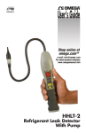
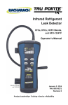
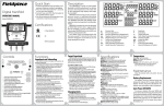
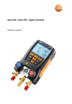
1
testo 316-3 · Leakage detector for refrigerants
Instruction manual
2
1 Contents
1
Contents
1
Contents ...................................................................................................3
2
Safety and the environment ....................................................................4
2.1. About this document ........................................................................4
2.2. Ensure safety...................................................................................4
2.3. Protecting the environment ..............................................................5
3
Specifications ..........................................................................................6
3.1. Use ..................................................................................................6
3.2. Technical data .................................................................................6
4
Product description .................................................................................8
4.1. Overview..........................................................................................8
5
First steps ................................................................................................9
5.1. Commissioning ................................................................................9
6
Using the product ..................................................................................11
6.1. Performing settings ........................................................................11
6.2. Finding leaks .................................................................................11
7
Maintaining the product ........................................................................12
8
Tips and assistance...............................................................................14
8.1. Questions and answers .................................................................14
8.2. Accessories and spare parts .........................................................14
3
2 Safety and the environment
2
Safety and the environment
2.1.
About this document
Use
> Please read this documentation through carefully and
familiarize yourself with the product before putting it to use. Pay
particular attention to the safety instructions and warning advice
in order to prevent injuries and damage to the products.
> Keep this document to hand so that you can refer to it when
necessary.
> Hand this documentation on to any subsequent users of the
product.
Warnings
Always pay attention to information that is marked by the following
warnings with warning pictograms. Implement the specified
precautionary measures.
Representation
WARNING
Indicates potential serious injuries
CAUTION
indicates potential minor injuries
NOTICE
2.2.
Explanation
indicates circumstances that may lead to
damage to the products
Ensure safety
> Only operate the product properly, for its intended purpose and
within the parameters specified in the technical data. Do not
use any force.
> The testo 330 must be checked before commissioning for any
visible damage. Do not commission the testo 330 if there are
signs of damage on the housing, mains unit or supply lines.
Electrical risk.
> Do not perform contact measurements on non-insulated, live
parts.
> Do not store the product together with solvents. Do not use any
desiccants.
4
2 Safety and the environment
> Carry out only the maintenance and repair work on this
instrument that is described in the documentation. Follow the
prescribed steps exactly. Use only original spare parts from
Testo.
> Temperatures given on probes/sensors relate only to the
measuring range of the sensors. Do not expose handles and
feed lines to any temperatures in excess of 70 °C unless they
are expressly permitted for higher temperatures.
2.3.
Protecting the environment
> Dispose of faulty rechargeable batteries/spent batteries in
accordance with the valid legal specifications.
> At the end of its useful life, send the product to the separate
collection for electric and electronic devices (observe local
regulations) or return the product to Testo for disposal.
> Dispose of faulty rechargeable batteries/spent batteries in
accordance with the valid legal specifications.
5
3 Specifications
3
Specifications
3.1.
Use
The testo 316-3 is a leakage detector for fast and reliable leak
detection in refrigeration systems and heat pumps. Gas concentrations are
indicated both visually and audibly.
The testo 316-3 is not protective equipment! Do not use the
testo 316-3 as a monitoring instrument for personal safety.
3.2.
6
Technical data
Feature
Values
Sensor
Electrochemical sensor with
heated diode
Detectable refrigerants
All HFCs, HCFCs and CFCs
(e.g. R134a, R410a, R438A,
R22 etc.)
Response threshold
<4 g/a / <0.15 oz/a
Sensor service life
80-100 hours (equates to
approx. 1 year of normal usage)
Warm-up period (switching
instrument on – ready to
measure)
Approx. 20 s
Power supply
Alkaline Batteries (2xD)
Battery life
16 hours
Storage/transportation
conditions
0 to 50 °C / 32 to 122 °F
3 Specifications
Feature
Values
Operating conditions
-20 to 50 °C / -4 to 122 °F
20 % - 80 %RH, non-condensing
Weight
Approx. 400 g (incl. batteries)
Dimensions (L x W x H)
Housing: approx. 270 x 65 x
65 mm
Length of flexible sensor shaft
including sensor head: approx.
285 mm
Warranty
Measuring instrument: 2 years
(sensor excluded), For warranty
terms see
www.testo.com/warranty
EC Directives
2004/108/EC
Standards
SAE J1627
EN14624:2012
7
4 Product description
4
Product description
4.1.
Overview
1
2
3
4
5
6
8
Flexible probe shaft with probe
head
Handle with battery
compartment
Battery indicator PWR (green
LED)
On/off button, sensitivity
Sensitivity indicator HI (high) /
LO (low)
Gas concentration indicator
(yellow LEDs)
5 First steps
5
First steps
5.1.
Commissioning
Installing the sensor
1. Unscrew the protective cap (1) from the sensor head (counterclockwise).
2. Take the sensor (2) out of its protective film packaging.
3. Carefully push the three sensor wires into the sockets in the
sensor head, until they are no longer visible.
NOTICE
Malfunction due to damaged sensor wires!
> Do not damage sensor wires.
4. Put the protective cap on the sensor and tighten by turning in a
clockwise direction.
Insert batteries
1. Using a screwdriver, push down the locking clip on top of the
handle.
2. Slide the top part of the handle down.
3. Insert two mono (D) type batteries. Observe the polarity!
9
5 First steps
4. Slide the top part of the handle back on.
Switch on
WARNING
Danger of explosion!
> The instrument must not be used in environments where
flammable gases are present.
> Press [
] briefly.
- PWR LED lights up and all yellow gas concentration indicator
LEDs start to flash one after another.
- The sensor is heated up.
- The instrument is ready to use once the gas concentration
indicator LEDs have gone off and one beep per second can be
heard.
Switch off
> Press and hold down [
10
].
6 Using the product
6
Using the product
6.1.
Performing settings
Setting the sensitivity
There are two sensitivity levels: HI (high, default) and LO (low).
The LO level is 8x less sensitive than the HI setting. At high
refrigerant gas concentrations, set the sensitivity to LO.
6.2.
> Press [
] briefly to set the sensitivity to LO.
> Press [
] again to revert to the HI level.
Finding leaks
NOTICE
Sensor destruction due to desorbing substances (e.g. oils)!
> Do not operate the instrument in contaminated environments.
1. Move the leakage detector to the site where the leak is
suspected.
Leak detection can only be carried out correctly if the probe
is guided directly over the leak.
2. Guide the probe head over the surface to be tested at a
maximum distance of 6 mm and a rate of 2.5 to 5 cm per
second.
-
If the instrument detects a leak, the yellow gas concentration
indicator LEDs light up and the instrument starts to beep
rapidly. The larger the leak, the more segments light up.
3. Move instrument away from the leak briefly.
> In the case of high refrigerant concentrations: before going back
to the leak, set the sensitivity to LO.
4. Guide the probe head back to the leak in order to precisely
locate the site.
> Set the sensitivity back to HI as soon as the leak has been
precisely located.
11
7 Maintaining the product
7
Maintaining the product
Cleaning the instrument
> If the housing of the instrument is dirty, clean it with a damp
cloth.
Do not use any aggressive cleaning agents or solvents! Weak
household cleaning agents and soap suds may be used.
Replacing the sensor
The electrochemical sensor has a service life of approximately
100 operating hours. Once this time is up, or if you suspect that
some leaks have not been detected, the sensor must be replaced.
CAUTION
Risk of burns due to hot sensor head!
> Before removing the protective cap: switch instrument off and
let the sensor head cool down.
1. Unscrew the protective cap (1) from the sensor head (anticlockwise).
2. Remove defective sensor.
3. Take the new sensor (2) out of its protective film packaging.
4. Carefully push the three sensor wires into the sockets in the
sensor head, until they are no longer visible.
NOTICE
Malfunction due to damaged sensor wires!
> Do not damage sensor wires.
5. Put the protective cap on the sensor head and tighten by
turning in a clockwise direction.
Replacing the filter
The filter must be replaced if it is clogged with water or oil or if it
appears to be dirty.
12
7 Maintaining the product
CAUTION
Risk of burns due to hot sensor head!
> Before removing the protective cap: switch instrument off and
let the sensor head cool down.
1. Unscrew the protective cap (1) from the sensor head (anticlockwise).
2. Push the spent filter (3) out of the protective cap using a paper
clip or something similar.
3. Insert the new filter into the protective cap.
4. Put the protective cap on the sensor head and tighten by
turning in a clockwise direction.
Changing batteries
Once PWR starts to flash, this indicates that the battery has
enough power left for approximately one hour.
1. Using a screwdriver, push down the locking clip on top of the
handle.
2. Slide the top part of the handle down.
3. Remove the spent batteries.
4. Insert two mono (D) type batteries. Observe the polarity!
5. Slide the top part of the handle back on.
13
8 Tips and assistance
8
Tips and assistance
8.1.
Questions and answers
Question
Possible causes
Possible solution
All gas concentration
indicator segments are lit
up, audible signal is off
Sensor is missing or is no
longer fully functional
>
Change sensor.
At the smallest of
movements, the
instrument signals a leak
•
Sensor wires are
kinked.
>
•
Sensor has been
exposed to a high
degree of humidity for
too long.
>
Remove sensor and
examine wires. If
necessary,
straighten wires with
pincers.
Switch the
instrument on and
wait until the alarm
switches off
(duration: up to
20 minutes).
Instrument is not very
Sensor has reached the end >
sensitive, seems to ignore of its service life.
leaks or does not detect
some types of refrigerant.
Change sensor.
Instrument cannot be
switched on.
Change batteries.
Batteries are depleted.
>
If we have not been able to answer your question, please contact
your local dealer or the Testo Customer Service. Contact details
can be found on the internet at www.testo.com/service-contact
8.2.
Accessories and spare parts
Description
Item no.
Replacement sensor
0554 2610
Replacement filter
0554 2611
For other accessories and spare parts, please refer to the product
catalogues and brochures or look up on the internet at
www.testo.com
14
8 Tips and assistance
15
0970 3163 en 03 V01.00