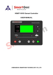
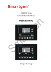
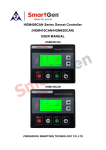
1
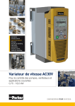
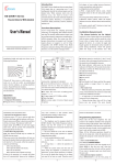
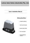
HGM9580 Bus Tie Bus Parallel Unit USER MANUAL Smartgen Technology Chinese trademark English trademark Smartgen — make your generator smart Smartgen Technology Co., Ltd. No. 28 Jinsuo Road Zhengzhou city Henan Province P. R. China Tel: +86-371-67988888/67981888 +86-371-67991553/67992951 +86-371-67981000(overseas) Fax: 0086-371-67992952 Web: http://www.smartgen.com.cn http://www.smartgen.cn Email: [email protected] All rights reserved. No part of this publication may be reproduced in any material form (including photocopying or storing in any medium by electronic means or other) without the written permission of the copyright holder. Smartgen Technology reserves the right to change the contents of this document without prior notice. Version history Date 2014-02-16 Version 1.0 Contents Original release HGM9580 BUS TIE BUS PARALLEL UNIT This manual is suitable for HGM9580 bus tie bus parallel unit only. Clarification of notation used within this publication. SIGN NOTE INSTRUCTION Highlights an essential element of a procedure to ensure correctness. Indicates a procedure or practice, which, if not strictly observed, could result in CAUTION! damage or destruction of equipment. Indicates a procedure or practice, which could result in injury to personnel or WARNING! loss of life if not followed correctly. HGM9580 Bus Tie Bus Parallel Unit ISSUE 2014-02-16 Version 1.0 Page 3 of 33 HGM9580 BUS TIE BUS PARALLEL UNIT CONTENTS 1 OVERVIEW ....................................................................................................... 5 2 PERFORMANCE AND CHARACTERISTICS ................................................... 6 3 SPECIFICATION ............................................................................................... 7 4 OPERATION ..................................................................................................... 8 4.1 INDICATOR LIGHT ......................................................................................................... 8 4.2 PUSHBUTTONS ............................................................................................................. 9 4.3 LCD DISPLAY ............................................................................................................... 10 4.3.1 MAIN DISPLAY .......................................................................................................... 10 4.3.2 USER MENU AND PARAMETERS SETTING MENU ............................................... 10 4.4 AUTO OPERATION ....................................................................................................... 13 4.5 MANUAL OPERATION .................................................................................................. 14 5 PROTECTIONS ............................................................................................... 15 5.1 5.2 WARNING ALARMS ...................................................................................................... 15 TRIP ALARM ................................................................................................................. 16 6 WIRING CONNECTION .................................................................................. 17 7 SCOPES AND DEFINITIONS OF PROGRAMMABLE PARAMETERS ............................... 20 7.1 CONTENTS AND SCOPES OF PARAMETERS ............................................................ 20 7.2 ENABLE DEFINITION OF PROGRAMMABLE OUTPUT PORTS.................................. 24 7.2.1 DEFINED COMBINATION OUTPUT ......................................................................... 26 7.3 DEFINED CONTENTS OF PROGRAMMABLE INPUT PORTS (ALL ACTIVE WHEN CONNECT TO GRAND (B~)) .................................................................................................... 27 8 TYPICAL DIAGRAM ....................................................................................... 29 9 TYPICAL APPLICATION ................................................................................ 30 10 INSTALLATION .............................................................................................. 31 11 USB ................................................................................................................. 32 12 FAULT FINDING ............................................................................................. 33 HGM9580 Bus Tie Bus Parallel Unit ISSUE 2014-02-16 Version 1.0 Page 4 of 33 HGM9580 BUS TIE BUS PARALLEL UNIT 1 OVERVIEW HGM9580 Bus Tie Bus Parallel Unit is designed for manual/auto parallel system which composed by multi-way bus and multi-way bus. It allows automatic parallel running function. It fit with LCD display, graphic display, optional Chinese, English and other languages interface, and it is reliable and easy to use. HGM9580 Bus Tie Bus Parallel Unit controls a bus breaker which can control the controller to synchronize the two ways buses via MSC CAN if the synchronization requirements have satisfied. The powerful 32-bit Microprocessor contained within the unit allows for precision parameters measuring, fixed value adjustment, time setting and set value adjusting and etc..Majority parameters can be configured from front panel, and all parameters can be configured by USB interface (or RS485) to adjust via PC. It can be widely used in all types of automatic genset parallel system with compact structure, simple connections and high reliability. HGM9580 Bus Tie Bus Parallel Unit ISSUE 2014-02-16 Version 1.0 Page 5 of 33 HGM9580 BUS TIE BUS PARALLEL UNIT 2 PERFORMANCE AND CHARACTERISTICS With ARM-based 32-bit SCM, high integration of hardware and more reliable; 480x272 TFT LCD with backlight, multilingual interface (including English, Chinese or other languages) which can be chosen at the site, making commissioning convenient for factory personnel; Improved LCD wear-resistance and scratch resistance due to hard screen acrylic; Silicon panel and pushbuttons for better operation in high/low temperature environment; RS485 communication port enables remote control, remote measuring, remote communication via ModBus protocol. Suitable for 3-phase 4-wire, 3-phase 3-wire, single phase 2-wire, and 2-phase 3-wire systems with voltage 120/240V and frequency 50/60Hz; Collects and shows 3-phase voltage and frequency of Bus 1/Bus 2. Bus 1 Bus 2 Line voltage (Uab, Ubc, and Uca) Line voltage (Uab, Ubc, and Uca) Phase voltage (Ua, Ub, and Uc) Phase voltage (Ua, Ub, and Uc) Phase sequence Phase sequence Frequency (Hz) Frequency (Hz) Synchronization parameters:Voltage Difference Between Bus 1 and Bus 2, Frequency Difference Between Bus 1 and Bus 2, Phase Difference Between Bus 1 and Bus 2; All output ports are relay output; Parameter setting: parameters can be modified and stored in internal EEPROM memory and cannot be lost even in case of power outage; most of them can be adjusted using front panel of the controller and all of them can be modified using PC via USB or RS485 ports; Widely power supply range DC(8~35)V, suitable to different starting battery voltage environment; Event log, real-time clock function; All parameters used digital adjustment, instead of conventional analog modulation with normal potentiometer, more reliability and stability; IP55 waterproofness level can be achieved with the help of rubber-ring gasket between shell and control panel. Metal fixing clips enable perfect in high temperature environment; Modular design, self extinguishing ABS plastic shell, pluggable terminal, built-in mounting, compact structure with easy installation; HGM9580 Bus Tie Bus Parallel Unit ISSUE 2014-02-16 Version 1.0 Page 6 of 33 HGM9580 BUS TIE BUS PARALLEL UNIT 3 SPECIFICATION Parameter Working Voltage Overall Consumption AC Input: 3 Phase 4 Wire 3 Phase 3 Wire Single Phase 2 Wire 2 Phase 3 Wire Alternator Frequency Flexible Relay Output 1 Flexible Relay Output 2 Flexible Relay Output 3 Flexible Relay Output 4 Flexible Relay Output 5 Flexible Relay Output 6 Flexible Relay Output 7 Flexible Relay Output 8 Case Dimensions Panel Cutout Working Conditions Storage Conditions Protection Level Insulation Intensity Weight HGM9580 Bus Tie Bus Parallel Unit Details DC8. 0V to 35. 0V, continuous power supply <4W (Standby mode: ≤2W) AC15V - AC360V (ph-N) AC30V - AC620V (ph- ph) AC15V - AC360V (ph-N) AC15V - AC360V (ph-N) 50Hz/60Hz 7A DC28V power supply output 7A DC28V power supply output 7A DC28V power supply output 7A AC250V volts free output 7A AC250V volts free output 7A AC250V volts free output 16A DC28V power supply output 16A DC28V power supply output 266mm x 182mm x 45mm 214mm x 160mm Temperature: (-25~+70)°C Humidity: (20~93)%RH Temperature:(-25~+70)°C IP55 Gasket Apply AC2.2kV voltage between high voltage terminal and low voltage terminal; The leakage current is not more than 3mA within 1min. 0.95kg ISSUE 2014-02-16 Version 1.0 Page 7 of 33 HGM9580 BUS TIE BUS PARALLEL UNIT 4 OPERATION 4.1 INDICATOR LIGHT NOTE: Selected light indicators description: Warning indicator and Alarm indicator: Alarm Type Warning Indicator Warning Slow flashing Trip Alarm Off Alarm Indicator Slow flashing Fast flashing Running indicator: It is light on when both of bus 1 and bus 2 are normal; off when either of them is abnormal. Bus 1 normal light:It is light on when bus 1 is normal; off when bus 1 is abnormal. Bus 2 normal light:It is light on when bus 2 is normal; off when bus 2 is abnormal. HGM9580 Bus Tie Bus Parallel Unit ISSUE 2014-02-16 Version 1.0 Page 8 of 33 HGM9580 BUS TIE BUS PARALLEL UNIT 4.2 PUSHBUTTONS Alarm Reset If alarm occurs, pressing the button can reset this alarm. Manual Mode Press this key and controller enters in Manual mode. Auto Mode Press this key and controller enters in Auto mode. Mute Alarming sound off. Lamp test Press this key can test the lamp is normal or not (lamp test). Close Can control bus to switch on in Manual mode. Open Can control bus to switch off in Manual mode. Up/Increase Down/Decrease 1) Screen scroll; 2) Up cursor and increase value in setting menu. 1) Screen scroll; 2) Down cursor and decrease value in setting menu. Left 1) Screen scroll; 2) Left move cursor in setting menu. Right 1) Screen scroll; 2) Right move cursor in setting menu. Set/Confirm Exit 1) Pressing and holding for more than 3 seconds enters parameter setting menu; 2) In settings menu confirms the set value. 1) Return to main menu; 2) Return to previous menu in setting menu. WARNING: Default password is 00318, user can change it in case of others change the advanced parameters setting. Please clearly remember the password after changing. If you forget it, please contact Smartgen services and send all PD information in the controller page of “ABOUT” to us. HGM9580 Bus Tie Bus Parallel Unit ISSUE 2014-02-16 Version 1.0 Page 9 of 33 HGM9580 BUS TIE BUS PARALLEL UNIT 4.3 LCD DISPLAY 4.3.1 MAIN DISPLAY Main screen show pages; use to scroll the pages and to scroll the screen. ★Main Screen, including as below, Bus 1: voltage, frequency, active power, reactive power Bus 2: voltage, frequency, active power, reactive power Some status ★Status, including as below, Module status, ATS status ★SNYC, including as below, Voltage difference, frequency difference, angle difference, MSC status ★Alarm Display all alarm information (warning alarm, trip alarm). ★Event log Make records about all events (trip alarm, power on events and Bus switch events) and the real time when events occur. ★Others, including, Time and Date, input/output ports status. ★About, including, Issue time of software and hardware version, product PD number. 4.3.2 USER MENU AND PARAMETERS SETTING MENU Press key for more than 3s to enter into user manual. ★Parameter After entering the correct password (factory default password is 00318) you can enter parameter settings screen. ★Language Selectable Chinese, English and others (default: Espanol) Parameter setting including as following, ★Battery setting ★Bus settings ★Breaker settings ★Input port settings ★output port settings HGM9580 Bus Tie Bus Parallel Unit ISSUE 2014-02-16 Version 1.0 Page 10 of 33 HGM9580 BUS TIE BUS PARALLEL UNIT ★Module settings ★Synchronization settings Example: Return Battery setting Bus setting Breaker setting > Input setting Output setting Module setting Synchronization setting > Close Delay > Open Delay Return Battery setting Bus setting Breaker setting > Close Delay > Open Delay Form1: Use to scroll settings, to enter settings (form 2), to exit settings menu. Form 2: Use to scroll settings, to enter settings, > to return to previous menu. (form 1) Input setting Output setting Module setting Synchronization setting Return Battery setting Bus setting > Close Delay > Open Delay to scroll settings, to contirm settings (form 4), Breaker setting > Input setting Output setting Module setting Synchronization setting > Close Delay > Open Delay Form 3: Use to return to previous menu. (form 1) 00003 Form 4 : Press (form 5), to enter settings to return to previous menu. (form 6). HGM9580 Bus Tie Bus Parallel Unit ISSUE 2014-02-16 Version 1.0 Page 11 of 33 HGM9580 BUS TIE BUS PARALLEL UNIT > Close Delay > Open Delay 00003 Form 5: Press to change cursor position, are used for changing cursor value, to confirm setting (form 4), to exit setting (form 4). > Close Delay > Open Delay 00003 Form 6: Use to scroll settings. enter settings (form 4), to to return to previous menu. (form 1). HGM9580 Bus Tie Bus Parallel Unit ISSUE 2014-02-16 Version 1.0 Page 12 of 33 HGM9580 BUS TIE BUS PARALLEL UNIT 4.4 AUTO OPERATION Auto mode is selected by pressing the button; a LED besides the button will illuminate to confirm the operation. 1. When remote start input is active: a) If either of the two buses is deactivate, then bus close signal will be initiated and the bus will be paralleled with the other bus; b) If both of Bus 1 and Bus 2 are active, the controller will adjust frequency and voltage to synchronize bus with bus; when synchronism requirements has been achieved, bus close signal will be initiated and the bus will be paralleled with the other bus. 2. When remote start input is deactivate, then bus open relay activate and the bus split from the other bus. Note: The bus voltage is regarded as active if it has exceeded the dead bus voltage (the dead bus voltage is configurable); otherwise, it is regarded as deactivate. HGM9580 Bus Tie Bus Parallel Unit ISSUE 2014-02-16 Version 1.0 Page 13 of 33 HGM9580 BUS TIE BUS PARALLEL UNIT 4.5 MANUAL OPERATION Manual mode is selected by pressing the button; a LED besides the button will illuminate to confirm the operation. 1. Press button: If either of the two buses is deactivate, then bus close signal will be initiated and the bus will be paralleled with the other bus. If both of Bus 1 and Bus 2 are active, the controller will adjust frequency and voltage to synchronize bus with bus; when synchronism requirements has been achieved, bus close signal will be initiated and the bus will be paralleled with the other bus. 2. Press button, then bus open relay activates and the bus split from the other bus. HGM9580 Bus Tie Bus Parallel Unit ISSUE 2014-02-16 Version 1.0 Page 14 of 33 HGM9580 BUS TIE BUS PARALLEL UNIT 5 PROTECTIONS 5.1 WARNING ALARMS Warnings are not shutdown alarms and do not affect the operation of the gen-set. Warning alarms does not lead to shutdown. Warning alarms types are as follows: No Type Description When the controller detects that the battery voltage has exceeded 1 Battery Over Volt the pre-set value, it will initiate a warning alarm. When the controller detects that the battery voltage has fallen 2 Battery Under Volt below the pre-set value, it will initiate a warning alarm. When the controller detects that the bus close status is not 3 Bus Breaker Fail configured in the input port, it will initiate a warning alarm. When the digit input port is set as User Configured and the action 4 Digital Input select “Warn”, it will initiate a warning alarm. When the controller does not detect synchronization signal within 5 Fail to sync the pre-set synchronization time, it will initiate a warning alarm. When the controller detects fewer modules on the MSC link than the minimum number configured in the unit, it will initiate a warning Min Sets Not alarm. There are 2 possible reasons: a) Communication line 6 Reached between the controllers disconnects, which interrupts communication. b) Other parallel gen-sets controllers have not been powered on. HGM9580 Bus Tie Bus Parallel Unit ISSUE 2014-02-16 Version 1.0 Page 15 of 33 HGM9580 BUS TIE BUS PARALLEL UNIT 5.2 TRIP ALARM On initiation of the trip condition the controller will de-energize the ‘Close Generator’ Output without stop the generator. Trip alarm as following, No Type 1 2 3 4 5 6 7 8 Description When the digit input port is set as User Configured and the action Digital Input select “Trip”, it will initiate a trip alarm. When the controller does not detect synchronization signal within Fail to sync the pre-set synchronization time, it will initiate a trip alarm. When the controller detects that the bus breaker is failed, it will Bus Breaker Fail initiate a trip alarm. When the controller detects fewer modules on the MSC link than the minimum number configured in the unit, it will initiate a trip alarm. There are 2 possible reasons: a) Communication line MSC Too Few Sets between the controllers disconnects, which interrupts communication. b) Other parallel gen-sets controllers have not been powered on. Bus 1 Phase When the controller detects a bus 1 phase rotation error, it will Sequence Wrong initiate a trip alarm. Bus 2 Phase When the controller detects a bus 2 phase rotation error, it will Sequence Wrong initiate a trip alarm. When the controller detects the same ID on the MSC Bus, it will MSC ID Error initiate a trip alarm. When the controller detects that the genset has already closed but Volt Bus Error there is no voltage on bus, it will initiate a trip alarm. HGM9580 Bus Tie Bus Parallel Unit ISSUE 2014-02-16 Version 1.0 Page 16 of 33 HGM9580 BUS TIE BUS PARALLEL UNIT 6 WIRING CONNECTION HGM9580 controller’s rear as following: Description of terminal connection: 1 DC input B- Cable Size 2.5mm2 2 DC input B+ 2.5mm2 3 4 5 COM Output 7,8 Aux. output 7 Aux. output 8 2.5mm2 1.5mm2 1.5mm2 6 Aux. output 1 1.5mm2 7 Aux. output 2 1.5mm2 8 Aux. output 3 1.5mm2 9 Reserved / 10 Aux. input 1 1.0mm2 11 Aux. input 2 1.0mm2 12 Aux. input 3 1.0mm2 NO. Functions HGM9580 Bus Tie Bus Parallel Unit Remark Connected with negative of starter battery. Connected with positive of starter battery. If wire length is over 30m, better to double wires in parallel. Max. 20A fuse is recommended. Connected with B+. B+ is supplied by 3 point, rated 16A. B+ is supplied by 3 point, rated 16A. B+ is supplied by 2 point, rated 7A. B+ is supplied by 2 point, Details see form 2. rated 7A. B+ is supplied by 2 point, rated 7A. This is reserved terminals, do not connect to wire. Ground connected is active (B-) Ground connected is Details see form 3. active (B-) Ground connected is active (B-) ISSUE 2014-02-16 Version 1.0 Page 17 of 33 HGM9580 BUS TIE BUS PARALLEL UNIT NO. Cable Size Functions 13 Aux. input 4 1.0mm2 14 Aux. input 5 1.0mm2 15 Aux. input 6 1.0mm2 Input COM 16 17-18 Reserved / / 19 1.0mm2 Aux. input 7 20 21 Aux. output 4 1.5mm2 22 23 24 25 26 27 28 33 34 35 MSC1 CAN MSC1 CAN H MSC1 CAN L MSC2 CAN MSC2 CAN H MSC2 CAN L RS485 RS485+ RS485- 2.5mm2 36 37 Aux. output 5 Aux. output 6 42 43 44 45 46 2.5mm2 2.5mm2 40 41 2.5mm2 2.5mm2 38 39 / 0.5mm2 0.5mm2 / 0.5mm2 0.5mm2 / 0.5mm2 0.5mm2 Bus 2 A-phase voltage sensing input Bus 2 B-phase voltage sensing input Bus 2 C-phase voltage sensing input Bus 2 N-wire input Bus 1 A-phase voltage sensing input Bus 1 B-phase voltage sensing input HGM9580 Bus Tie Bus Parallel Unit 1.0mm2 1.0mm2 1.0mm2 1.0mm2 1.0mm2 1.0mm2 Remark Ground connected active (B-) Ground connected active (B-) Ground connected active (B-) is is is This is reserved terminals, do not connect to wire. Ground connected is Details see form 3. active (B-) Normally close outputs, rated 7A. Public points of relay Details see form 2. Normally open outputs, rated 7A. Impedance-120Ω shielding wire is recommended, its single-end earthed. Impedance-120Ω shielding wire is recommended, its single-end earthed. Impedance-120Ω shielding wire is recommended, its single-end earthed. Normally close outputs, rated 7A. Normally open outputs, rated 7A. Details see form 2. Public points of relay Normally open outputs, rated 7A. Public points of relay Connected to A-phase of Bus 2 (2A fuse is recommended). Connected to B-phase of Bus 2 (2A fuse is recommended). Connected to C-phase of Bus 2 (2A fuse is recommended). Connected to N-wire of Bus 2. Connected to A-phase of Bus 1 (2A fuse is recommended). Connected to B-phase of Bus 1 (2A fuse is recommended). ISSUE 2014-02-16 Version 1.0 Page 18 of 33 HGM9580 BUS TIE BUS PARALLEL UNIT NO. 47 48 Functions Cable Size Bus 1 C-phase voltage 1.0mm2 sensing input Bus 1 N-wire input 1.0mm2 Remark Connected to C-phase of Bus 1 (2A fuse is recommended). Connected to N-wire of Bus 1. NOTE: USB ports in controller rear panel are configurable parameter ports, user can directly program controller via PC. HGM9580 Bus Tie Bus Parallel Unit ISSUE 2014-02-16 Version 1.0 Page 19 of 33 HGM9580 BUS TIE BUS PARALLEL UNIT 7 SCOPES AND DEFINITIONS OF PROGRAMMABLE PARAMETERS 7.1 CONTENTS AND SCOPES OF PARAMETERS Form 1 No. Items Parameters Defaults Description Battery Setting 1 Rated Voltage (0-60.0)V 24.0 2 Over Voltage (0-200)% 120% 3 Under Voltage (0-200)% 85% AC System (0~3) 0 2 Volt. Trans.(PT) Switch Setting (0-1) 0 1 Close Time (0~20.0)s 5.0 2 Open Time Module Setting 1 Power On Mode (0~20.0)s 3.0 (0~1) 0 2 Module Address (1~254) 1 3 Stop Bit (0~1) 0 4 Language (0~2) 0 5 Password (0~65535) 00318 Flexible Input Port 1 1 Contents Setting (0~50) 28 2 Active Type (0~1) 0 Flexible Input Port 2 1 Contents Setting (0~50) 0 2 Active Type (0~1) 0 3 Arming (0~2) 2 Standard for checking battery over/under voltage. Setting value is rated voltage’s percentage, return value (default: 115%) and delay value (default: 60s) can be set. Setting value is rated voltage’s percentage, return value (default: 90%) and delay value (default: 60s) can be set. Bus Setting 1 0: 3P4W; 1: 3P3W; 2: 2P3W; 3: 1P2W. 0: Disable; 1:Enable Pulse width of switch on. When it is 0, means output constantly. Pulse width of switch off. 0: Manual mode 1: Auto mode Controller’s address during remote sensing. 0: 2 stop bits; 1: 1 stop bit 0: Simplified Chinese 1: English 2: Others For entering advanced parameters setting. Flexible Input Ports HGM9580 Bus Tie Bus Parallel Unit ISSUE 2014-02-16 Remote OnLoad. See form 3 0: Closed to active 1: Open to active User defined. See form 3 0: Closed to active 1: Open to active 0: From paralleling 1: Always Version 1.0 2:Never Page 20 of 33 HGM9580 BUS TIE BUS PARALLEL UNIT No. Items 4 5 Active Actions Active Delay 6 Description Parameters Defaults Description (0~2) (0~20.0)s 2 2.0 0: Warn; 1:Trip 2: Indication Time from detecting active to confirm LCD display detailed contents when the input is active. Flexible Input Port 3 1 Contents Setting (0~50) 0 2 Active Type (0~1) 0 3 4 5 Arming Active Actions Active Delay (0~2) (0~2) (0~20.0)s 2 2 2.0 6 Description User defined. See form 3 0: Closed to active 1: Open to active 0: From paralleling 1: Always 2:Never 0: Warn; 1:Trip 2: Indication Time from detecting active to confirm LCD display detailed contents when the input is active. Flexible Input Port 4 1 Contents Setting (0~50) 13 2 Active Type (0~1) 0 Flexible Input Port 5 1 Contents Setting (0~50) 0 2 Active Type (0~1) 0 3 4 5 Arming Active Actions Active Delay (0~2) (0~2) (0~20.0)s 2 2 2.0 6 Description Flexible Input Port 6 1 Contents Setting (0~50) 0 2 Active Type (0~1) 0 3 4 5 Arming Active Actions Active Delay (0~2) (0~2) (0~20.0)s 2 2 2.0 6 Description Flexible Input Port 7 1 Contents Setting (0~50) 0 2 Active Type (0~1) 0 3 Arming (0~2) 2 4 5 Active Actions Active Delay (0~2) (0~20.0)s 2 2.0 6 Description HGM9580 Bus Tie Bus Parallel Unit ISSUE 2014-02-16 Bus Closed. See form 3 0: Closed to active 1: Open to active User defined. See form 3 0: Closed to active 1: Open to active 0: From paralleling 1: Always 2:Never 0: Warn; 1:Trip 2: Indication Time from detecting active to confirm LCD display detailed contents when the input is active. User defined. See form 3 0: Closed to active 1: Open to active 0: From paralleling 1: Always 2:Never 0: Warn; 1:Trip 2: Indication Time from detecting active to confirm LCD display detailed contents when the input is active. User defined. See form 3 0: Closed to active 1: Open to active 0: From paralleling 1: Always 2: Never 0: Warn; 1:Trip 2: Indication Time from detecting active to confirm LCD display detailed contents when the input is active. Version 1.0 Page 21 of 33 HGM9580 BUS TIE BUS PARALLEL UNIT No. Items Parameters Defaults Description Flexible Output Ports Flexible Output Port 1 1 Contents Setting (0~239) 44 2 (0~1) 0 Flexible Output Port 2 1 Contents Setting (0~239) 48 2 (0~1) 0 Flexible Output Port 3 1 Contents Setting (0~239) 46 2 (0~1) 0 Flexible Output Port 4 1 Contents Setting (0~239) 47 2 (0~1) 0 Flexible Output Port 5 1 Contents Setting (0~239) 30 2 (0~1) 0 Flexible Output Port 6 1 Contents Setting (0~239) 29 2 (0~1) 0 Flexible Output Port 7 1 Contents Setting (0~239) 0 2 (0~1) 0 Flexible Output Port 8 1 Contents Setting (0~239) 0 2 (0~1) 0 Active Type Active Type Active Type Active Type Active Type Active Type Active Type Active Type Bus 1 OK. See Form 2 0:Normally open; 1:Normally close Common Alarm. See Form 2 0:Normally open; 1:Normally close Bus 2 OK. See form 2 0:Normally open; 1:Normally close Synchronizing. See form 2 0:Normally open; 1:Normally close Open Bus Output. See form 2 0:Normally open; 1:Normally close Close Bus Output. See form 2 0:Normally open; 1:Normally close Not Used. See form 2 0:Normally open; 1:Normally close Not Used. See form 2 0:Normally open; 1:Normally close Sync Setting 1 MSC ID (0-31) 1 2 Dead Bus Volt (10-50)V 30 3 Slip Frequency (0-1.00)Hz 0.10 HGM9580 Bus Tie Bus Parallel Unit ISSUE 2014-02-16 It is the ID mark of the MSC communication internet. All the MSC ID should be unique. It is considered Bus no power when Bus voltage is lower than dead Bus voltage. Adjust bus frequency and enable it greater than the other bus frequency. When slip frequency is 0: If the frequency difference is greater than 0.1Hz, then the frequency will be Version 1.0 Page 22 of 33 HGM9580 BUS TIE BUS PARALLEL UNIT No. Items Parameters Defaults 4 Voltage Difference (0-30)V 3 5 Positive Difference Freq (0-2.0)Hz 0.2 6 Negative Difference Freq (0-2.0)Hz 0.1 7 Phase Difference Angle (0-20)° 10 8 Fail to Sync Delay (5.0-300.0)s 60.0 9 Fail to Sync Action (0-1) 0 10 11 12 13 14 Sync Freq Gain Sync Freq Stab. Sync Volt Gain Sync Volt Stab. MSC Number Too Few Modules Action (0~500) (0~2000) (0~500) (0~2000) (1-32) 20 20 20 20 2 (0-2) 1 Baud Rate (0-3) 1 15 16 HGM9580 Bus Tie Bus Parallel Unit ISSUE 2014-02-16 Description synchronized; If the frequency difference is smaller than 0.1Hz, then the phase will be synchronized; The voltage difference between bus 1 and bus 2. It is considered voltage synchronization when the voltage difference between Bus 1 and Bus 2 is lower than synchronization voltage difference. The frequency difference between bus 1 and bus 2. It is considered frequency synchronization when the frequency difference between bus 1 and bus 2 is less than Positive Freq Difference but more than Negative Freq Difference. Initial phase difference between bus 1 and bus 2. It is considered Check Phase Angle when the initial phase difference is lower than synchronization phase difference. When the controller detects no Sync signal during the preset delay, it will send corresponding alarm signal according to the action type. Action Type: 0:Warn;1:Trip. Adjust and control before paralleling. Adjust and control before paralleling. Adjust and control before paralleling. Adjust and control before paralleling. Action Type: 0:No Action;1:Warn;2:Trip. 0:500Kbit/s;1:250Kbit/s; 2:125Kbit/s;3:50Kbit/s. Version 1.0 Page 23 of 33 HGM9580 BUS TIE BUS PARALLEL UNIT 7.2 ENABLE DEFINITION OF PROGRAMMABLE OUTPUT PORTS Form 2 No. Type 0 1~6 7 8 9 10 11 12 13~17 Not Used Reserved Custom Combined 1 Custom Combined 2 Custom Combined 3 Custom Combined 4 Custom Combined 5 Custom Combined 6 Reserved 18 Audible Alarm 19~25 26 27~28 29 30 31~43 44 45 46 47 Reserved Remote Control Output Reserved Close Bus Output Open Bus Output Reserved Bus 1 OK Reserved Bus 2 OK Synchronizing 48 Common Alarm 49 50 51 52 53 54 55 56~68 69 70 71 72 73 74 75 76~230 231 232 Reserved Reserved Common Trip Common Warn Reserved Battery Over Voltage Battery Under Voltage Reserved Digital Input 1 Active Digital Input 2 Active Digital Input 3 Active Digital Input 4 Active Digital Input 5 Active Digital Input 6 Active Digital Input 7 Active Reserved Manual Mode Reserved HGM9580 Bus Tie Bus Parallel Unit Description Details of function description please see the following. Action when warning, trips. Can be connected annunciator externally. When “alarm mute” configurable input port is active, it can remove the alarm. This port is controlled by communication (PC). Control bus to take load. Control bus to off load. Action when bus 1 is normal. Action when bus 2 is normal. Action when controller is synchronizing. Action when genset common warning or common trips alarm. Action when common trips alarm. Action when common warning alarm. Action when battery’s over voltage warning alarm. Action when battery’s low voltage warning alarm. Action when input port 1 is active Action when input port 2 is active Action when input port 3 is active Action when input port 4 is active Action when input port 5 is active Action when input port 6 is active Action when input port 7 is active Action in Manual mode. ISSUE 2014-02-16 Version 1.0 Page 24 of 33 HGM9580 BUS TIE BUS PARALLEL UNIT 233 234 235~239 Auto Mode Bus Load Reserved HGM9580 Bus Tie Bus Parallel Unit Action in Auto mode. ISSUE 2014-02-16 Version 1.0 Page 25 of 33 HGM9580 BUS TIE BUS PARALLEL UNIT 7.2.1 DEFINED COMBINATION OUTPUT Defined combination output is composed by 3 parts, condition output S1 or S2 and condition output S3. S1 or S2 is TRUE, while S3 is TRUE, Defined combination output is outputting; S1 and S2 are FALSE, or S3 is FALSE, Defined combination output is not outputting. NOTE: S1, S2, S3 can be set as any contents except for “defined combination output” in the output setting. NOTE: 3 parts of defined combination output (S1, S2, S3) couldn’t include or recursively include themselves. Example, Contents of probably condition output S1: output port 1 is active; Close when probably condition output S1 is active /inactive: close when active (disconnect when inactive); Contents of probably condition output S2, output port 2 is active; Close when probably condition output S2 is active /inactive: close when active (disconnect when inactive); Contents of probably condition output S3: output port 3 is active; Close when probably condition output S3 is active /inactive: close when active (disconnect when inactive); When input port 1 active or input port 2 active, if input port 3 is active, Defined combination output is outputting; If input port 3 inactive, Defined combination output is not outputting; When input port 1 inactive and input port 2 inactive, whatever input port 3 is active or not, Defined combination output is not outputting. HGM9580 Bus Tie Bus Parallel Unit ISSUE 2014-02-16 Version 1.0 Page 26 of 33 HGM9580 BUS TIE BUS PARALLEL UNIT 7.3 DEFINED CONTENTS OF PROGRAMMABLE INPUT PORTS (ALL ACTIVE WHEN CONNECT TO GRAND (B~)) Form 3 No. Type 0 Users Configured 1 2 3 4 5 Reserved Alarm Mute Reset Alarm Reserved Lamp Test 6 Panel Lock Description Including following functions, Indication: indicate only, not warning or shutdown. Warning: warn only. Trip: alarm, generator unloads but not shutdown. Never: input inactive. Always: input is active all the time. From paralleling: detect when the genset is parallel running. Can prohibit “Audible Alarm” output when input is active. Can reset trip alarm when input is active. All LED indicators are illuminating when input is active. All buttons in panel is inactive except and there is in the right of first row in LCD when input is active. 7~12 13 14 15~16 Reserved Aux Bus Closed Inhibit Bus Load Reserved Connect bus loading switch’s Aux. Point. Prohibit bus switch on when input is active. When input is active, controller enters into Auto mode; 17 Auto Mode Lock button is inactive. When input is active, controller won’t work under Auto 18 Auto Mode Invalid mode. key and simulate auto key input does not work. 19~21 22 23~27 Reserved Aux Instrument Mode Reserved All outputs are prohibited in this mode. 28 Remote Start (On Load) In Auto mode, when the input is active, bus can be paralleled automatically; when the input is inactive, bus will split automatically. 29~33 Reserved 34 Simulate Manual key 35 Reserved HGM9580 Bus Tie Bus Parallel Unit An external button (not self-locking) can be connected and pressed as simulate panel. ISSUE 2014-02-16 Version 1.0 Page 27 of 33 HGM9580 BUS TIE BUS PARALLEL UNIT 36 Simulate Auto key An external button (not self-locking) can be connected and pressed as simulate panel. 37 38 39 40~50 Reserved Simulate Close Button Simulate Open Button Reserved An external button (not self-locking) can be connected and pressed as simulate panel. HGM9580 Bus Tie Bus Parallel Unit ISSUE 2014-02-16 Version 1.0 Page 28 of 33 HGM9580 BUS TIE BUS PARALLEL UNIT 8 TYPICAL DIAGRAM HGM9580 Typical Diagram HGM9580 Bus Tie Bus Parallel Unit ISSUE 2014-02-16 Version 1.0 Page 29 of 33 HGM9580 BUS TIE BUS PARALLEL UNIT 9 TYPICAL APPLICATION HGM9580 Bus Tie Bus Parallel Unit ISSUE 2014-02-16 Version 1.0 Page 30 of 33 HGM9580 BUS TIE BUS PARALLEL UNIT 10 INSTALLATION Controller is panel built-in design; it is fixed by clips when installed. The controller’s overall dimensions and cutout dimensions for panel, please refers to as following, 1) Battery Voltage Input NOTE: HGM9580 controller can suit for widely range of battery voltage DC(8~35)V. Negative of battery must be connected with the engine shell. The diameter of wire which from power supply to battery must be over 2.5mm2. If floating charge configured, please firstly connect output wires of charger to battery’s positive and negative directly, then, connect wires from battery’s positive and negative to controller’s positive and negative input ports in order to prevent charge disturbing the controller’s normal working. 2) Output And Expand Relays CAUTION: All outputs of controller are relay contact output type. If need to expand the relays, please add freewheel diode to both ends of expand relay’s coils (when coils of relay has DC current) or, add resistance-capacitance return circuit (when coils of relay has AC current), in order to prevent disturbance to controller or others equipment. 3) Withstand Voltage Test CAUTION! When controller had been installed in control panel, if need the high voltage test, please disconnect controller’s all terminal connections, in order to prevent high voltage into controller and damage it. HGM9580 Bus Tie Bus Parallel Unit ISSUE 2014-02-16 Version 1.0 Page 31 of 33 HGM9580 BUS TIE BUS PARALLEL UNIT 11 USB Users can set the controller’s parameters and monitor the controller’s status via the test software which provided by Smartgen company. The connection way between PC and controller as following: HGM9580 Bus Tie Bus Parallel Unit ISSUE 2014-02-16 Version 1.0 Page 32 of 33 HGM9580 BUS TIE BUS PARALLEL UNIT 12 FAULT FINDING Symptoms Possible Solutions Check starting batteries; Controller no response with Check controller connection wirings; power. Check DC fuse. Check related switch and its connections according to the Shutdown Alarm in running information on LCD; Check auxiliary input ports. Genset running while ATS not Check ATS; transfer Check the connections between ATS and controllers. Check connections; Check setting of COM port is correct or not; RS485 communication is Check RS485’s connections of A and B is reverse connect or abnormal not; Check RS485 transfer module whether damage or not; Check communication port of PC whether damage. HGM9580 Bus Tie Bus Parallel Unit ISSUE 2014-02-16 Version 1.0 Page 33 of 33