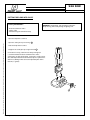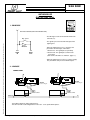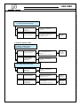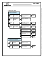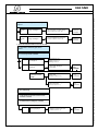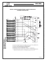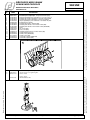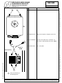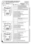
1
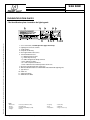
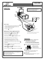
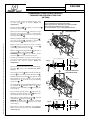
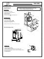
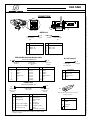
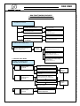
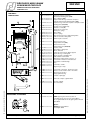
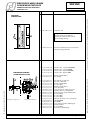
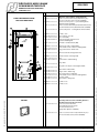
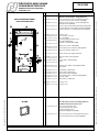
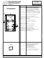
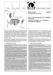
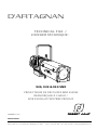
D'ARTAGNAN
TECHNICAL FILE /
DOSSIER TECHNIQUE :
930, 933 & 934 SNX
PROJECTEURS DE DÉCOUPES MSR 2500W
REAMORÇAGE À CHAUD /
MSR 2500W HOT RESTRIKE PROFILES
VALIDATION : 27.10.10
DN30750601
Robert Juliat S.A.S. Route de Beaumont, F 60530 Fresnoy-en-Thelle - phone : +33 (0)3 44 26 51 89 - fax : +33 (0)3 44 26 90 79 - [email protected]
Robert Juliat U.S.A. 48 Capital Drive, Wallingford, CT 06492 - phone : (203) 294 0481 - fax : (203) 294 0482 - [email protected]
ii
NOTES
iii
You have in your possession a ROBERT JULIAT profile. We would like to congratulate you on your
choice.
The performance of this profile depends on the care you'll give to its maintenance. We advise you
to read this manual and then keep it for reference.
Do not hesitate to come up with suggestions ; it's thanks to you that our products will continue
to improve.
Thank you.
ROBERT JULIAT
Vous venez de prendre possession de votre nouveau projecteur de découpe et nous vous
remercions de votre choix.
Le résultat que vous en obtiendrez dépendra pour beaucoup du soin que vous apporterez
à son entretien, aussi nous vous conseillons de lire ces quelques pages qui ont été écrites à
votre intention et de les conserver en cas de nécessité.
Ne manquez pas de nous faire part de vos idées ou suggestions ; c’est grâce à vous que le
produit pourra évoluer.
Merci de votre attention.
ROBERT JULIAT
iv
Section: A
CONTENTS
TECHNICAL DATA
User's instructions...................................................................................................... A - 1
The identification plates........................................................................................... A - 3
Connections................................................................................................................. A - 5
Putting the lamp into place..................................................................................... A - 7
Admissible lamps....................................................................................................... A - 9
Network use............................................................................................................... A - 11
Changing the position of the yoke - OPTION..................................................... A - 13
Section: B
MAINTENANCE
Reflector, aspheric lens and spark-gap................................................................. B - 1
Connection.................................................................................................................. B - 3
Non-functioning diagnosis........................................................................ B - 5, 7, 9, 11
Electrical diagram - lamp housing....................................................................... B - 14
Section: C
SPARE PARTS LIST
Lamp housing & accessoires..................................................................................... C - 1
Lamp housing and yoke blocking system............................................................. C - 2
930 Lens tube............................................................................................................... C - 3
934 Lens tube............................................................................................................... C - 4
933 Lens tube............................................................................................................... C - 5
Aspheric lens and lamp holder................................................................................ C - 6
Dimmer.......................................................................................................................... C - 7
900 SNX
USER’S
INSTRUCTIONS
TECHNICAL
FILE
2500W MSR PROFILES
Section A - 1
Please read carefully all the instructions before operating the appliance.
Robert Juliat reserve the right to change or alter any of the items detailed on this page, to increase or improve manufacturing techniques without prior notice.
GENERAL INSTRUCTIONS
1. Not for residential use.
2. Only qualified technicians are permitted to service these fixtures.
3. In addition to the instructions indicated on this page, you must
adhere to the relevant health and safety requirements of the
appropriate EU Directives.
4. This fixture is in compliance with section 17: Lighting appliance
for theatre stages, television, cinema and photograph studios.
Standards NF EN 60598-1 and NF EN 60598-2-17.
5. This fixture is rated as IP20, and is for indoor use only.
FIXTURE
6. Warning: high voltage ignition. Disconnect from the mains before
any servicing.
7. Make sure the fixture is correctly mounted on an appropriate
support.
8. The protection screens, lenses or U.V. filters must be replaced if there
is any visual damage which might reduce their performance, for
example, by cracks or deep scratches.
9. When hung or flown the fixture must be secured by another hanging
accessory (such as a safety cable or bond) that is of suitable length.
10.The safety bond or cable must be securely attached at the back of
the fixture. It must be as short as possible or rolled up as necessary
to ensure the fixture does not travel any distance should it be
dislodged.
11.Movable accessories (barn doors, HMI shutters, spill rings etc.) must
also be secured with a suitable safety cable or bond at the front of
the fixture.
12.Take into account the weight of both the fixture and the accessories
when choosing the strength of the attachment point and the safety
cable or bond.
13.Do not open the lighting fixture when the lamp is on.
14.Both the lamp and lamp housing heat up when powered. Wait until
the fixture is cold before servicing.
15.Do not tamper with the design of the fixture nor any of its safety
features.
16.Tighten the electrical mains cable connections regularly. Replace
mains cable with an identical one if damaged.
17.Use only with correct power supply.
Lamp
Danger
The discharge lamp used emits short-wave ultraviolet
radiation which is harmful to skin and eyes.
22.Use only fully enclosed in the fixture.
23.Never look at the lamp directly.
24.Warning: U.V. rays : Protect your eyes.
25.Check that the lamp voltage corresponds to the mains voltage used.
Do not use a lamp with power that is an incorrect type or voltage to
the one that is indicated on the lamp housing or packaging.
26.The lamp must be replaced if it has been damaged or deformed by
the heat.
27.Use only when bulb is in place.
Cleaning
28.Do not touch the lamp or the mirror with your fingers.
29.Keep optical parts (lens, lamps,…) clean with alcohol.
30.Regularly remove dust from the mirror with a soft and clean rag.
31.If the fixture has filters they must be cleaned frequently.
POWER SUPPLY
32.Disconnect from the mains before any servicing.
33.Mains connection only. Do not connect to an "electronic output"
(dimmer, static relay...).
34.Do not use outside. Do not cover.
35.The power supply has circuit breakers, which should always be kept
accessible.
36.There is no maximum distance between the lighting unit and the
power supply.
37.Check the mains voltage.
PLEASE NOTE
These products have been built to conform to European standards
relating to professional lighting equipment. Any modification made to
our products will void the manufacturers' warranty
Ventilation
18.Keep well away from flammable material.
19.Do not use outside. Do not cover. Do not permit the fixture to get
wet.
20.To avoid overheating, do not obstruct air vents.
21.If the fixture has fans, make sure they are working correctly. If fans
are not working, turn the fixture off immediately and service as
necessary.
robert juliat Route de Beaumont F 60530 Fresnoy-en-Thelle phone: +33 (0)3.44.26.51.89 - fax: +33 (0)3.44.26.90.79 - www.robertjuliat.fr
900 SNX
TECHNICAL FILE
2500W MSR PROFILES
Section A - 3
THE IDENTIFICATION PLATES.
- The identification plate situated on the lighting unit :
1
7
Robert Juliat reserve the right to change or alter any of the items detailed on this page, to increase or improve manufacturing techniques without prior notice.
2
1
2
3
4
5
6
7
8
9
10
11
12
Units :
- Dimensions
- Weight
- Intensity
- Voltage
11
6
9
8
3
10
4
12 5
User's instructions, read the previous page attentively.
Lighting unit's reference & name.
Serial number.
European conformity.
Net weight without accessories.
Technical characteristics :
- P = Maximum power input.
- AL = Max. amp intensity.
- UL =Max. voltage at the lamp terminal. - IP 20 = indoor use ONLY.
- t a = max temperature ambient.
- t max = Maximum external temperature of the unit.
Restrictive operating position : front view.
Minimum distance between a flammable material and the lighting unit.
Type of P.S.U.
Gobo size.
Admissible lamps.
WEEE directive label.
= metre (m) millimetre (mm).
= kilogram (kg).
= Ampere (A) milliampere (mA).
= Volt (V).
- Frequency
- Power
- Temperature
= Hertz (Hz).
= Watt (W).
= Degree Celsius (°C).
robert juliat Route de Beaumont F 60530 Fresnoy-en-Thelle phone: +33 (0)3.44.26.51.89 - fax: +33 (0)3.44.26.90.79 - www.robertjuliat.fr
900 SNX
TECHNICAL FILE
2500W MSR PROFILES
Section A - 5
CONNECTIONS.
Each time you switch on: make sure
the fans are working correctly.
A
h
e
OPTION
DMX colour
changer.
f
Robert Juliat reserve the right to change or alter any of the items detailed on this page, to increase or improve manufacturing techniques without prior notice.
g
Mains voltage.
D
B
C
5
3 4
1 2
- Check the conformity of the mains voltage input with
the values indicated on the identification plate of the
PSU (mains voltage & lamp power)
7
Rating plate 7 : Lamp power.
0/+10V. line.
6
DATA out.
Lighting unit / Power supply connection.
DATA in.
- Connect the lamp cable C to the connector 5 of the
ballast and connector e to the lighting unit.
• Use only the listed cables to connect to the mains Refer to the respective PSU technical file.
- Connect the cable D to the connector ( d ) of the
ballast and to the connector f of the lighting unit "XLR7".
- Place the lamp into position - refer to section A - 7.
- Connect the DATA line on connector ( a ) "XLR5" or
the analog command to the connector ( c ) "XLR4".
( For the connection configurations : refer to section B - 3 ).
- Connect the optional units that are possible, to connector g
( Only DATA ).
- Plug the cable 6 to the mains. If the power is present, the
checklight 1 lights up immediately.
- Engage the circuit breaker 3 and check that the CAD 900
protection 4 is well engaged.
- If you use the optional outlet h , engage the circuit breaker 2 .
DESCRIPTION.
A 900 SNX Motorized shutter - CAD 900 version.
e - EM HARTING 16 x 16A power socket.
f - EM XLR7 shutter + DATA (option).
g - EF XLR5 output DATA (colour changer option).
h - EF mains output 220/240V (colour changer option).
B Power supply unit with CAD 900 control module.
0/10V - DMX 512 - AVAB
ERROR
a
SELECT
DATA
EXT. DIGI.
LOCK
EXT.
LOCAL
RESET
b
DATA
CONTROL
WARNING !
- Never open the lamp house's bonnet when the lighting unit is on.
- Do not change the safety switches.
- Never connect to a dimmable channel.
- Use only when lamp in place.
+
EXIT
a
b
c
c
d d
- EM XLR5 input DATA.
- EF XLR5 output DATA.
- EM XLR4 0/+10V input.
- EF XLR7 output DATA luminaire.
0/10V
SHUTTER
C Lamp cable.
Cable H07 RN-F 18G 1,5 mm2 length 3m fitted
with 16 x 16A M/F HARTING connectors.
D Shutter cable.
14 conductors reinforced shielded cable - length 3m
fitted with XLR7 M/F connector.
robert juliat Route de Beaumont F 60530 Fresnoy-en-Thelle phone: +33 (0)3.44.26.51.89 - fax: +33 (0)3.44.26.90.79 - www.robertjuliat.fr
900 SNX
TECHNICAL FILE
2500W MSR PROFILES
Section A - 7
PUTTING THE LAMP INTO PLACE.
User's precautions :
- Disconnect from the mains.
- Lamp is cold.
- Avoid touching the bulb of the lamp.
WARNING : Fragile lamp - take the lamp out from the
lamp housing, when transporting the lighting unit.
- Open the lamp house's bonnet.
Robert Juliat reserve the right to change or alter any of the items detailed on this page, to increase or improve manufacturing techniques without prior notice.
- Open the socket jaws by unscrewing 1 .
- Place the lamp into the socket.
- Retighten the socket jaws by using the knob 1 .
For means of security, each time the lamp is changed, it
is recommended to check the condition of the socket
connections: the base of the lamp - socket jaws. A socket or the
base of a lamp which has become black, requires replacement.
Otherwise, damage will be caused to important parts of the
lantern (i.e. ignitor).
2500
1
robert juliat Route de Beaumont F 60530 Fresnoy-en-Thelle phone: +33 (0)3.44.26.51.89 - fax: +33 (0)3.44.26.90.79 - www.robertjuliat.fr
TECHNICAL FILE
2500W MSR PROFILES
900 SNX
Section A - 9
ADMISSIBLE LAMP :
PHILIPS: MSR 2500 HR
Robert Juliat reserve the right to change or alter any of the items detailed on this page, to increase or improve manufacturing techniques without prior notice.
Manufacturer's recommendations :
• Read attentively the manufacturer's instructions.
• Positioning of the lamp and connecting the power supply require great care. To make sure there is a good
conduction of current, the mechanical support and the electrical connections must be free from dirt and corrosion.
The clamps and brackets must be checked whenever the lighting unit has been transported.
• The lamp emits ultraviolet radiation. Direct exposure can be harmful to your health.
• It is recommended to avoid air draughts, also avoid exposing the lighting unit to bad weather.
• Use only when bulb in place
Technical characteristics :
Voltage at the terminals of the lamp.................................................................................................................................. 115 Volts
Amperage at the terminals of the lamp........................................................................................................................... 25,6 Amps
Luminosity of the lamp....................................................................................................................................................... 240 000 lm
Luminous efficacy.....................................................................................................................................................................96 lm/W
Colour temperature............................................................................................................................................................ 6000 Kelvin
Base....................................................................................................................................................................................................... G38
Manufacturer's rated life...................................................................................................................................................... 500 hours
User's precautions :
• The lamplife, as given by the manufacturer, is a theoretic lamplife duration as "in laboratory conditions",
a cycle based on 3 hours on / 1 hour off. Briefer cycles reduce the duration of the lamplife.
• In operating conditions, it is uncommon, for the lamp to still be fully efficient after 200 to 300 hours.
Its efficiency can decrease by 30%.
• Premature wearing of lamp under performing conditions is mainly due to frequent switching on. Better leave
the lamp on, through the performance, rather than switching it on repeatedly. ( The lamplife is reduced about
1 hour, each time the lamp is switched on ). It is advised to wait for 10 minutes before switching on again.
(This extends the duration of the lamp.)
• Use over 500 hours of the lamp : change the lamp even if it still lights up.
New lamp :
• To achieve a good ionization of a new lamp, when using it for the first time, it is recommended to leave it on
for a few hours.
• Preserve carefully the guarantee slip of the lamp, as it may be asked for in the event to resolve a dispute.
Thank you.
robert juliat Route de Beaumont F 60530 Fresnoy-en-Thelle phone: +33 (0)3.44.26.51.89 - fax: +33 (0)3.44.26.90.79 - www.robertjuliat.fr
900 SNX
TECHNICAL FILE
2500W MSR PROFILES
Section A - 11
NETWORK USE
DIGITAL (DMX - AVAB).
C A D 900
0/10V - DMX 512 - AVAB
ERROR
1 - PRINCIPLE.
SELECT
DATA
EXT. DIGI.
LOCAL
RESET
a
b
DATA
DATA OUT OPTION (ON THE LIGHTING UNIT).
CONTROL
c
d
0/10V
SHUTTER
- The DATA goes to the connector DATA IN on the
CAD 900 ( a ) .
By - pass
Robert Juliat reserve the right to change or alter any of the items detailed on this page, to increase or improve manufacturing techniques without prior notice.
+
EXIT
LOCK
EXT.
- The signal is present on the DATA output of the
lighting unit.
Booster
DATA
IN
DATA
OUT
- When the lighting unit is in use, there are two
possibilities for the output - DATA OUT :
1 : Booster on - The signal passes by an amp.
2 : Booster off - The signal passes on direct on
the output.
( Refer to the CAD 900 user's manual - page 11 ).
- When the lighting unit is not in use ( power supply
off ), the DATA is still present on DATA output.
2 - LINK USE.
CONNECTIONS
DATA only
ATHOS
a
DATA Link
IN
b
d
OUT
OPTION
Colour changer.
DATA only
ATHOS
Output
DATA +
Shutter control.
a
IN
b
d
OUT
OPTION
Colour changer.
Output
DATA +
Shutter control.
etc.
To install the DATA line, daisy chain all units.
You can not make a star configuration. In this case - use a specific DATA splitter.
robert juliat Route de Beaumont F 60530 Fresnoy-en-Thelle phone: +33 (0)3.44.26.51.89 - fax: +33 (0)3.44.26.90.79 - www.robertjuliat.fr
930SNX
SNX
900
TECHNICAL FILE
2500W MSR PROFILES
Section A - 13
CHANGEMENT DE POSITION DE FOURCHE /
CHANGING THE POSITION OF THE YOKE.
(OPTION)
- Dévisser les deux vis du porte-glissière droit et sortir
les deux tiges 1 (voir la schéma "ORDRE DE
DEMONTAGE").
- Dévisser les deux vis 2 et les quatre vis sous le zoom 3
puis retirer l'iris motorisé 4 .
ATTENTION / WARNING
•
•
•
•
Isoler électriquement avant toute intervention.
Matérial professionnel : Intervention par technicien qualifié.
Disconnet from the mains before any servicing.
Professional material : Service only by qualified technician.
Robert Juliat reserve the right to change or alter any of the items detailed on this page, to increase or improve manufacturing techniques without prior notice.
9
11
7
6 4
- Démonter la poignée côté droit et la vis côté gauche 7 ,
puis sortir la fourche 8 . Démonter le système de
blocage de fourche A côté droit (voir "Fig. 1").
10
- Ouvrir le capot de la lanterne et retirer le support
lentille 9 . Dévisser et retirer les trois vis et sortir 10
le doublage, puis démonter le cache 11 .
7
2
A
5
- Monter le système de blocage de fourche A* côté droit et
côté gauche 1* et la nouvelle fourche 2* .
ATTENTION la cale B doit être montée devant
l'entretoise C et non pas à l'arrière (voir "Fig 2").
- Procéder au remontage de toutes les pièces dans le
sens inverse comme expliqué dans les paragraphes
précédents (voir aussi le schéma "ORDRE DE
REMONTAGE").
3
côté droit / right-hand view
2*
- Reassemble the parts as explained in the paragraphs
above in reverse order (refer also to the "REASSEMBLING
ORDER" diagram).
(*) ORDRE DE REMONTAGE /
(*) REASSEMBLING ORDER.
4*
1*
5* 7*
3*
1*
11*
A*
9*
6*
- Open the lamp housing's bonnet 9 and remove the
optical lens set. Remove the three screws 10 and remove
the metal plate, then remove the cover 11 .
- Reassemble the yoke's blocking system A* , left and
right-hand side 1* , and the new yoke 2* .
WARNING the wedge plate B should be remounted
infront of the cone spacer C and not at the back
(refer to "fig. 2").
côté gauche / left-hand view
A
- Unscrew the two screws 2 and the four screws under the
lens tube 3 , then remove the motorised shutter unit 4 .
- Unscrew the handle on the right-hand side and the screw on
the left-hand side 7 and then remove the 8 yoke.
Dismantle the yoke's blocking system A on the right side
(refer to "Fig. 1").
1
"Fig. 1"
- Unscrew and remove the accessories slot holder and the
two rodes 1 (refer to the "DISMANTLING ORDER"
diagram).
- Untighten and remove the knob 5 , then push the knob
axle towards the interior. Push the rear lens holder
towards the front 6 to accede to the yoke's blocking
system screw A .
ORDRE DE DEMONTAGE /
DISMANTLING ORDER.
8
- Desserrer et retirer le bouton 5 , puis pousser la tige
du bouton vers l'intérieur. Avancer le porte-lentille
arrière vers l'avant 6 pour accéder à la vis du système
de blocage de fourche A .
8*
10*
côté droit / right-hand view
"Fig. 2"
côté gauche / left-hand view
B
C
A*
robert juliat Route de Beaumont F 60530 Fresnoy-en-Thelle phone: +33 (0)3.44.26.51.89 - fax: +33 (0)3.44.26.90.79 - www.robertjuliat.fr
900 SNX
DOSSIER TECHNIQUE
DECOUPES MSR 2500W
REFLECTOR.
Disconnect from the mains before any servicing.
Service only by qualified technician.
- Disconnect from the mains.
- Open the bonnet of the lamp house.
- Take out the lamp.
(Refer to section A - 7).
- Clean the reflector 1 with a soft dry cloth.
2
3
ASPHERIC LENS.
- Unscrew the lock 2 .
- Take out the lens holder set 3 .
- Clean the lens with a soft dry cloth.
- Remount the lens holder set.
1
- Clean in the same way, the lenses in the lens tube.
Check the lamp position.
MINI = 7mm.
SPARK-GAP.
- Disconnect from the mains.
- Open the lamp house bonnet.
- Check the distance of the electrodes that should be 1mm.
(If you notice a larger gap, then please contact the ROBERT JULIAT's
technical department).
[email protected]
1 mm
robert juliat Route de Beaumont F 60530 Fresnoy-en-Thelle phone: +33 (0)3.44.26.51.89 - fax: +33 (0)3.44.26.90.79 - www.robertjuliat.fr
Le constructeur se réserve la possibilité de modifier ses matériels sans avis préalable. Les renseignements mentionnés sur cette notice sont donnés à titre indicatif et ne sauraient présenter de caractère contractuel.
MAINTENANCE
Section B - 1
900 SNX
DOSSIER TECHNIQUE
DECOUPES MSR 2500W
CONNECTION.
g
DATA Link
a
Flexible cable
5 x 0,14 shielded
CN5
FM XLR 5
DESIGNATION
REP
1
2
3
4
5
b&f
FF XLR 5
DESIGNATION
REP
0V
DATA - IN
DATA + IN
1
2
3
4
5
Flexible cable
5 x 0,14 shielded
CN5
0V
DATA - OUT
DATA + OUT
CAD 900/Mechanical Shutter cable
Delivered standard : 3m
d
Flexible cable
14 x 0,14 shielded
CN14
CAD 900 side
FM XLR 7
DESIGNATION
REP
1
2
3
4
5
6
7
SHELL
4 x 0,14
1 x 0,14
1 x 0,14
1 x 0,14
1 x 0,14
3 x 0,14
3 x 0,14
Shielded
c
Shutter side
FF XLR 7
1
2
3
4
5
6
7
NC
Flexible cable
5 x 0,14 shielded
FF XLR 4
DESIGNATION
REP
0V
DATA DATA +
PWM
INFO 0/+10V
+U
-U
/
0/+10V control
e
0V
DATA DATA +
PWM
INFO 0/+10V
+U
-U
/
REP
1
2
3
4
DESIGNATION
0V GND
Lamp circuit
Shutter circuit
+15V
Lamp cable
Delivered standard : 3m
g
Cable H07 RN-F
18G 1,5mm2
Ballast side
FMD 16 x16 A
Harting
REP
1
2
3
4
5
6
7
8
DESIGNATION
Fan phase
Ballast phase
Lamp Neutral
Security return 1200W
Security return 2500W
Security not used
h
Lighting unit side
FFD 16 x16 A
Harting
REP
DESIGNATION
9
10
11
12
13
14
15
16
Ignition timed phase
Ballast phase
Lamp Neutral
Earth
Aux. phase
Aux. Neutral
Common security
Earth
Female side earth only
k
250V -10A IEC C14 male power connector,
for fan power feed.
REP
DESIGNATION
L
Phase
N
Neutral
Earth
Note: This is a universal cable and is suitable for a 1200W / 2500W
followspot or profile.
robert juliat Route de Beaumont F 60530 Fresnoy-en-Thelle phone: +33 (0)3.44.26.51.89 - fax: +33 (0)3.44.26.90.79 - www.robertjuliat.fr
Le constructeur se réserve la possibilité de modifier ses matériels sans avis préalable. Les renseignements mentionnés sur cette notice sont donnés à titre indicatif et ne sauraient présenter de caractère contractuel.
Section B - 3
900 SNX
DOSSIER TECHNIQUE
DECOUPES MSR 2500W
NON-FUNCTIONING DIAGNOSIS.
FOR MOTORISED MODELS (CAD 900)
NON-FUNCTIONING DIAGNOSIS.
The ballast does not work.
the mains checklight is not on
Check the mains.
the mains checklight is on
the CAD 900 is not on
Check that the circuit breaker
is engaged.
Check the CAD fuse.
the CAD still does not work :
Contact the RJ service.
Message displayed :
RJ LAMP ERR.
Contact the RJ service.
The CAD fuse blows out while in use.
Disconnect the shutter connection
and then change the fuse.
Switch on
the ballast.
If the fuse blows again - change
the CAD: ( refer to section C - 10 ).
The CAD stays on - check the
shutter cable connection.
(refer to sections A - 5 & A - 11 )
1. USING THE "AUTO" MODE .
1.1 The ballast and the CAD are on ;
the "lamp on" command is given,
but the lamp does not switch on.
message displayed :
RJ LAMP LIGHTING
TRY FAILURE
No ignition sound.
Reconnect the shutter cable :
If the problem comes back : Change
the whole block.
( refer to section C - 7 )
Check that the lantern bonnet is well
closed.
Check that the cable is well connected.
(refer to sections A - 5 & A - 11 )
Restart the
"LAMP ON"
procedure.
Check that the correct cable has
been used.
message displayed :
RJ LAMP LIGHTING
TRY FAILURE
ignition sound.
Check that the lamp is in good
condition, in any doubt : change it.
(counter lamplife : page 6/7 - manual CAD)
Check the mains voltage >200 V.
Restart the
"LAMP ON"
procedure.
Check that the ignition is well adjusted
( refer to section B - 1 )
message displayed :
RJ LAMP LIGHTING
TRY FAILURE
Contact ROBERT JULIAT's
technical department
robert juliat Route de Beaumont F 60530 Fresnoy-en-Thelle phone: +33 (0)3.44.26.51.89 - fax: +33 (0)3.44.26.90.79 - www.robertjuliat.fr
Le constructeur se réserve la possibilité de modifier ses matériels sans avis préalable. Les renseignements mentionnés sur cette notice sont donnés à titre indicatif et ne sauraient présenter de caractère contractuel.
Section B - 5
DECOUPES MSR 2500W
900 SNX
Section B - 7
1.2. Untimely extinction of the lamp.
message displayed :
LAMP OFF
CHECK SECURITY
Return to 1.1 and follow the
procedure.
Network transient failure : give the
off command, or switch off
the mains for 30 sec.
Restart the
"LAMP ON"
procedure.
message unchanged.
Check the analog command cable :
the command has not been
received.
( refer to sections A - 5 & A - 11 )
Restart the
"LAMP ON"
procedure.
message displayed :
RJ LAMP LIGHTING
TRY FAILURE
Return to 1.1 and follow the
procedure.
message unchanged.
2. USING THE " ANALOG " MODE
2.1. The ballast and the CAD are on ;
the" lamp on" command is given,
but the lamp does not switch on.
2.2. Untimely extinction of the lamp.
message displayed :
LAMP FAILURE
CHECK SECURITY
Return to 1.1 and follow the
procedure.
message unchanged.
Network transient failure : give the
off command, or switch off
the mains for 30 sec.
Restart the
"LAMP ON"
procedure.
Message in
start-up display :
" RJ LAMP OFF "
Command signal failure :
check the cable
( refer to sections A - 5 & A - 11 )
Restart the
"LAMP ON"
procedure.
robert juliat Route de Beaumont F 60530 Fresnoy-en-Thelle phone: +33 (0)3.44.26.51.89 - fax: +33 (0)3.44.26.90.79 - www.robertjuliat.fr
Le constructeur se réserve la possibilité de modifier ses matériels sans avis préalable. Les renseignements mentionnés sur cette notice sont donnés à titre indicatif et ne sauraient présenter de caractère contractuel.
DOSSIER TECHNIQUE
DECOUPES MSR 2500W
900 SNX
Section B - 9
3. USING THE " DIGI " MODE.
3.1.The ballast and the CAD are on ;
the " lamp on" command is given ,
but the lamp does not switch on.
Green
LED
on.
Green
LED
on.
message unchanged.
message displayed :
RJ LAMP LIGHTING
TRY FAILURE.
Green &
red LED
off.
message unchanged.
Green &
red LED
on.
message unchanged.
No circuit number "lamp channel"
assigned : refer to page 9 of the
CAD 900 manual.
Restart the
"LAMP ON"
procedure.
Return to 1.1 and follow the
procedure.
Transmission Data error :
connection failure : check cable.
( refer to sections A - 5 & A - 11 ).
Restart the
"LAMP ON"
procedure.
Transmission Data error :
connection faulty or damaged check the wiring.
Restart the
"LAMP ON"
procedure.
Important disruption on the Data
line : check the installation.
Restart the
"LAMP ON"
procedure.
Bad Protocol : refer to page 7 of the
CAD 900 manual.
Restart the
"LAMP ON"
procedure.
Protocol recognition locked :
refer to page 15 of the
CAD 900 manual - The preferences.
Restart the
"LAMP ON"
procedure.
3.2. Untimely extinction of the lamp.
Green
LED
on.
Green
LED
on.
message displayed :
LAMP FAILURE
CHECK SECURITY
message unchanged.
Return to 1.1 and follow the
procedure.
Network cut off :
give the off command.
Restart the
"LAMP ON"
procedure.
robert juliat Route de Beaumont F 60530 Fresnoy-en-Thelle phone: +33 (0)3.44.26.51.89 - fax: +33 (0)3.44.26.90.79 - www.robertjuliat.fr
Le constructeur se réserve la possibilité de modifier ses matériels sans avis préalable. Les renseignements mentionnés sur cette notice sont donnés à titre indicatif et ne sauraient présenter de caractère contractuel.
DOSSIER TECHNIQUE
DECOUPES MSR 2500W
900 SNX
Section B - 11
3.3. The off command is given, but the lamp
stays on.
Green &
red LED :
off
message unchanged.
Transmission Data error :
connection failure : check the wiring.
( refer to sections A - 7 & A - 14 ).
Resend the
"LAMP OFF"
command.
Green &
red LED
on.
message unchanged.
connection damaged or disturbed :
( refer to sections A - 7 & A - 14 ).
Resend the
"LAMP OFF"
command.
4 . NON-FUNCTIONING DIAGNOSIS FOR THE SHUTTER :
1.1 The shutter command is given, but no
action.
1.2 . The shutter only excepts an up command,
does not accept a down command.
New shutter level
not displayed.
Command link error :
Digital - refer to 3.1.
Analog - refer to 2.
New shutter level
displayed.
Shutter cable damaged :
Check cable.
The shutter does
not react or reacts
badly.
resend the
level
command.
Faulty power supply :
Change CAD :
( Refer to section C - 10 )
resend the
level
command.
Motor damaged : Change the
whole shutter unit.
( refer to section C - 7 )
resend the
level
command.
Error on the shutter unit :
Change the whole shutter unit.
( refer to section C - 7 )
resend the
level
command.
1.3 . The shutter reacts badly, and the motor
runs continuously.
1.4. The shutter act in a saw-tooth movement
on a fluent command.
1.5. Shutter action is delayed to command.
The shutter level is
correctly displayed.
robert juliat Route de Beaumont F 60530 Fresnoy-en-Thelle phone: +33 (0)3.44.26.51.89 - fax: +33 (0)3.44.26.90.79 - www.robertjuliat.fr
Le constructeur se réserve la possibilité de modifier ses matériels sans avis préalable. Les renseignements mentionnés sur cette notice sont donnés à titre indicatif et ne sauraient présenter de caractère contractuel.
DOSSIER TECHNIQUE
900 SNX
DOSSIER TECHNIQUE
DECOUPES MSR 2500W
B
A
MODIFICATIONS
VERSION : ALIMENTATION MAGNÉTIQUE
/ MAGNETIC POWER SUPPLY
Indice
Date
Description
LANTERNE / LAMP HOUSING
2ème raccordement sur point 15 du composant “A” vers point N du composant “D” et dessin “F” corrigé.
Code silog du ventilateur “D”à été modifié.
Rectification sur le raccordement entre le point 3 du composant “A” et le point 3 du composant “B”.
Nom
16/12/99
16/12/99
24/02/10
E.G.
E.G.
E.W.
4
T
A
Phase Ventilateur / Fan
Phase - Tempo / Timer
Phase - Ballast
Phase - Ballast
Neutre lampe /
Lamp neutral
Neutre lampe /
Lamp neutral
1
9
2
10
3
11
P
T
N
P
N
D
0,75
12
2,5
1
2,5
2,5
2,5
Neutre Aux. /
Aux. neutral
Sécurité retour /
Commun return
PLAN ELECTRIQUE /
ELECTRICAL DIAGRAM
Sécurité commun /
Commun security
13
2,5
7
15
2,5
Terre chassis /
Frame earth
16
T
3
4
0,75
N
L
0,75
0,75
F
T
0,75
0,75
8
Terre / Earth
#6HT
HT
6
14
C
3
5
Phase Aux.
#6HT
HT
4
Terre / Earth
B
T
E
NO
T1
2,5
NC
2,5
C
Terre lanterne /
Earth of lamp house.
2
A : Connecteur Mâle Harting 16 x 16A / Male connector 16 X 16 Amps (COU0016101).
B : Amorceur 2500W / Ignition block 2500W (ME15100003).
C : Lampe / Lamp - HMI 2500 W/SE ou/or MSR 2500HR.
D : Ventilateur / Fan (Papst 4890N)( ME14220207).
E : Minirupteur sécurité / Security switch - 220/240V. A.C.(ME04200001).
F : Embase femelle IEC C13 / IEC C13 female socket - 2p + T 10A 250V (COU0003250).
(Utilisation maximum autorisée = 2A / Maximum authorised used = 2A.
Nota : Conception et validation du plan d’origie par E.G.
Matière: ---------
Indice: Dessiné par:
Créé le:
Edité le :
Vérifié par :
1
20/05/10
21/03/95
SCHEMA ELECTRIQUE LANTERNE 2500W EP: --------E.G.
C
Traitement: --------A404504-C
Ce plan est la propriété de la société
Ech Robert
:
COMPATIBLE ALIMENTATION :
Juliat. Toute reproduction,
Peinture: --------même partielle est formellement
A4 Folio
/
1/1
interdite sans autorisation.
Poids: --------robert MAGNETIQUE
juliat Route de Beaumont
F 60530 Fresnoy-en-Thelle phone: +33 (0)3.44.26.51.89 - fax: +33 (0)3.44.26.90.79 - www.robertjuliat.fr
/ ELECTRONIQUE
Sans autre spécification:
N° plan RJ
Rep
LAN_Elec_A404504_C.eps
ième
±0,15.
Le constructeur se réserve la possibilité de modifier ses matériels sans avis préalable. Les renseignements mentionnés sur cette notice sont donnés à titre indicatif et ne sauraient présenter de caractère contractuel.
C
D
a
b
C
Section B - 13
DÉCOUPES MSR 2500W
2500W MSR PROFILES
900 SNX
NOMENCLATURE PIECES DETACHEES /
SPARE PARTS LIST.
Section C - 1
2
1
4
3
5
7
6
9
8
10
12
15
17
18
19
20
21
22
23
24
25
2
3
DJ40468200
DJ30468100
3
FPADIV0027
4
5
6
PO00000001
DU40426401
DT40425600
7
8
9
10
11
DU40423500
DT40429901
DU40440000
RPAFIX0056
RPAFIX0052
12 P D 9 0 0 0 0 0 0 9
14
16
DJ30468000
12 P D 9 0 0 0 0 0 0 8
11
13
1
13
14
15
16
17
18
19
20
21
22
23
24
25
AFGA000001
AFG0000002
MI00000002
DJ40504600
DU40422603
DU40236104
PD90000003
PD10130017
COU0003246
DU40242901
VI19050002
DU40376800
DU40182901
DESCRIPTION
Plaque fixe blocage couteaux /
Fixed shutter blocking plate. (930).
Etrier / Bracket. (930).
Plaque mobile blocage couteaux complète /
Complete mobile shutter blocking plate. (930).
Plaque blocage couteaux complète / Complete shutter
blocking plate. (933/934).
Poignée seule / Handle only.
Entretoise / Strut (Ø6).
Ressort presse couteaux /
Shutter press spring.
Galet / Roller.
Ressort / Spring.
Galet de blocage zoom / Zoom locking roller.
Câble de sécurité / Safety cable.
Maillon rapide / Fast link.
Tôlerie lanterne vide /
Empty lantern unit (930).
Tôlerie lanterne vide /
Empty lantern unit (933/934).
Crochet / Hook.
Grenouillère / Safety lock.
Miroir / Reflector.
Plaque de retenu miroir / Mirror support.
Tige de blocage / Locking rod.
Tige de guidage / Guidance rod.
Câble douille / Socket cable.
Minirupteur / Micro switch (03/2000 -->).
Connecteur ventilateur / Fan connector.
Palier téflon / Teflon bearing.
Clips.
Colonnette / Shank.
Bague borgne / Caps.
27
26 C O U 0 0 1 6 1 0 1
27 C O U 0 0 0 3 2 5 0
28 P D 9 0 0 0 0 0 1 0
28
29 M E 1 5 1 1 0 0 0 1
Connecteur / Connector - Harting 16 x 16A.
Embase secteur / Mains socket - 220/240V.
Boîtier amorceur vide /
Empty ignitor housing.
Eclateur / Spark-gap.
30 M E 1 5 1 0 0 0 0 3
Amorceur complet / Ignition block.
31 P O 0 0 0 0 0 0 2 1
32 V I 0 8 0 1 0 0 2 4
Poignée / Handle.
Vis / Screw (M8).
33 F P A D I V 0 0 4 6
SGUX Support gobo universel, taille "A"
pour Gobo métal, verre ou verre dépoli Ø100 /
"A" size gobo holder for metal, glass gobo or frosted
glass Ø100.
26
29
30
31
Measurements are in mm / Mesures en mm.
32
ACCESSOIRES / ACCESSORIES
33
34 O P 1 0 0 5 1 0 0 1
Option :
VD100 Verre dépoli Ø100 /
Frosted glass Ø100.
34
! ATTENTION - Pour passer une commande de pièces détachées, utiliser toujours les codes. / WARNING - Always use the codes, when ordering spare parts. !
Le constructeur se réserve la possibilité de modifier ses matériels sans avis préalable. Les renseignements
mentionnés sur cette notice sont donnés à titre indicatif et ne sauraient présenter de caractère contractuel.
LANTERNE /
LAMP HOUSING
CODE
Robert Juliat reserve the right to change or alter any of the items detailed on this
page, to increase or improve manufacturing techniques without prior notice.
P
RE
DÉCOUPES MSR 2500W
2500W MSR PROFILES
900 SNX
NOMENCLATURE PIECES DETACHEES /
SPARE PARTS LIST.
Section C - 2
P
RE
CODE
DESCRIPTION
ME14220207
A chaque mise en route: vérifier le bon
fonctionnement des ventilateurs /
Each time you switch on: make sure the
fans are working correctly.
2
1
BLOCAGE DE FOURCHE /
YOKE BLOCKING SYSTEM
3
1
14
Measurements are in mm / Mesures en mm.
19
5
8
2
20
4
18
16
7
10 11
9
15
13
12
17
30
0
Côté gauche / Left-hand view.
6
Ventilateur / Fan.
21
Côté droit / Right-hand view.
2
COU0003139
Connecteur d'alimentation des ventilateurs /
Fans power supply connector.
1
DJ30414904
DJ20395105
DJ30414906
DJ20395106
Fourche / Yoke
Fourche / Yoke
Fourche / Yoke
Fourche / Yoke
2
3
VI10030003
DJ40482201
Rondelle / Washer (Ø10).
Cale / Wedge.
4
5
6
7
8
9
10
11
12
13
14
15
16
17
DJ30482001
DU30482100
VI06030003
VI06010012
VI10030003
VI10020001
DU40477700
VI10030009
PO00000025
VI10010021
VI05010033
VI05010043
DJ40517300
DJ40434101
DJ40434102
DJ40517103
VI10030003
VI10010020
DE40487300
Cône femelle / Female cone.
Cône mâle / Male cone.
Rondelle / Washer (Ø6).
Vis / Screw (M6).
Rondelle / Washer (Ø10).
Ecrou / Nut (M10).
Canon de fourche / Canon cross piece.
Rondelle à plateau / Spring washer.
Poignée femelle / Female handle (M10).
Vis / Screw (M10).
Vis / Screw (M5).
Vis / Screw (M5).
Entretoise de fixation cône / Cone spacer.
Index (933/934).
Index (930).
Canon épaulé côté libre / Blocking nut.
Rondelle/ Washer.
Vis / Screw (M10).
Bande repère / Bearing strip.
18
19
20
21
- Standard (933/934).
- Standard (930).
- Option (933/934).
- Option (930).
! ATTENTION - Pour passer une commande de pièces détachées, utiliser toujours les codes. / WARNING - Always use the codes, when ordering spare parts. !
Robert Juliat reserve the right to change or alter any of the items detailed on this
page, to increase or improve manufacturing techniques without prior notice.
1
Le constructeur se réserve la possibilité de modifier ses matériels sans avis préalable. Les renseignements
mentionnés sur cette notice sont donnés à titre indicatif et ne sauraient présenter de caractère contractuel.
LANTERNE /
LAMP HOUSING
DÉCOUPES MSR 2500W
2500W MSR PROFILES
930 SNX
NOMENCLATURE PIECES DETACHEES /
SPARE PARTS LIST.
Section C - 3
1
PD70000006
2
PD60000011
DJ20534701
2
1
DJ20534702
7
3
13
6
5
8
10
4
12
9
14
11
15
16
23
21
22
20
24
Measurements are in mm / Mesures en mm.
25
19
14
18
DESCRIPTION
Glissières avant simples / Single front slot :
Pour accessoires 215 x 215 (standard Français) /
For 215 x 215 accessories (French standard).
Verrou à ressort 3 pièces / 3 piece locking device.
(Only for French standard).
Pour accessoires 254 x 254 (standard Nord-Américain) /
For 254 x 254 accessories (North-American standard).
Verrou seul pour d° / Locking device for item above.
3
4
5
6
OP20010003
DU40423601
VI04010053
DU40454400
7
VI04030005
Lentille / Lens.
Pince lentille / Lens clip.
Vis / Screw (M4).
Fourreau guidage lentille avant /
Front lens holder guide.
Rondelle / Contact washer (M4).
8
9
10
ME11050204
900P023003
DU40063800
Maintien de câble / Cable holder.
Porte lentille avant / Front lens sliding holder.
Tige porte bouton / Knob screw.
11
900P021107
Tôlerie zoom vide /Empty zoom unit.
12
13
14
BO10000008
VI14050001
DU40754800
Bouton moleté / Focusing knob.
Clip.
Palier Téflon / Teflon bearing.
15
DJ30226216
Tige / Rod.
16
FPADIV0025
Support verre dépoli / Frosted glass holder.
18
19
20
21
22
23
DU40165101
DU40165102
DU40183900
900P021103
AFGA000001
AFG0000002
Galet delrin / Plastic roller.
Bague delrin / Plastic ring.
Axe porte bouton / Knob axle.
Porte lentille arrière / Rear lens sliding holder.
Crochet / Hook.
Grenouillère / Safety lock.
24
25
OP11010005
OP11010004
Lentille / Lens.
Lentille / Lens.
700P043100
Cassette porte accessoires à double glissières /
Double slot cassette for accessories :
Pour accessoires 245 x 245
(standard Européen & Japon) /
For 245 x 245 accessories
(European & Japanese standard).
700P040100
Pour accessoires 215 x 215 (standard Français) /
For 215 x 215 accessories (French standard).
12
OPTION
! ATTENTION - Pour passer une commande de pièces détachées, utiliser toujours les codes. / WARNING - Always use the codes, when ordering spare parts. !
Le constructeur se réserve la possibilité de modifier ses matériels sans avis préalable. Les renseignements
mentionnés sur cette notice sont donnés à titre indicatif et ne sauraient présenter de caractère contractuel.
PIECES INTERIEURES ZOOM /
LENS TUBE INNER PARTS
CODE
Robert Juliat reserve the right to change or alter any of the items detailed on this
page, to increase or improve manufacturing techniques without prior notice.
P
RE
DÉCOUPES MSR 2500W
2500W MSR PROFILES
934 SNX
NOMENCLATURE PIECES DETACHEES /
SPARE PARTS LIST.
Section C - 4
2
1
PD70000006
2
PD60000011
DJ20534701
1
DJ20534702
3
13
7
6
12
9
14
11
15
17
14
16
23
22
20
24
Measurements are in mm / Mesures en mm.
25
19
21
Glissières avant simples / Single front slot :
Pour accessoires 215 x 215 (standard Français) /
For 215 x 215 accessories (French standard).
Verrou à ressort 3 pièces / 3 piece locking device.
(Only for French standard).
Pour accessoires 254 x 254 (standard Nord-Américain) /
For 254 x 254 accessories (North-American standard).
Verrou seul pour d° / Locking device for item above.
4
5
8
10
DESCRIPTION
18
12
3
4
5
6
OP20010004
DU40423601
VI04010053
DU40454400
7
VI04030005
Lentille / Lens.
Pince lentille / Lens clip.
Vis / Screw (M4).
Fourreau guidage lentille avant /
Front lens holder guide.
Rondelle / Contact washer (M4).
8
9
10
ME11050204
900P023003
DU40063800
Maintien de câble / Cable holder.
Porte lentille avant / Front lens sliding holder.
Tige porte bouton / Knob screw.
11
900P023002
Tôlerie zoom vide / Empty zoom unit.
12
13
14
15
BO10000008
VI14050001
DU40754800
DJ30226214
Bouton moleté / Focusing knob.
Clip.
Palier Téflon / Teflon bearing.
Tube.
16
17
FPADIV0025
DJ30223225
Support verre dépoli / Frosted glass holder.
Tige / Rod.
18
19
20
21
22
23
DU40165101
DU40165102
DU40183900
900P023005
AFGA000001
AFG0000002
Galet delrin / Plastic roller.
Bague delrin / Plastic ring.
Axe porte bouton / Knob axle.
Porte lentille arrière / Rear lens sliding holder.
Crochet / Hook.
Grenouillère / Safety lock.
24
25
OP11040001
OP11010004
Lentille / Lens.
Lentille / Lens.
OPTION
700P043100
700P040100
Cassette porte accessoires à double glissières /
Double slot cassette for accessories :
Pour accessoires 245 x 245
(standard Européen & Japon) /
For 245 x 245 accessories
(European & Japanese standard).
Pour accessoires 215 x 215 (standard Français) /
For 215 x 215 accessories ( French standard).
! ATTENTION - Pour passer une commande de pièces détachées, utiliser toujours les codes. / WARNING - Always use the codes, when ordering spare parts. !
Le constructeur se réserve la possibilité de modifier ses matériels sans avis préalable. Les renseignements
mentionnés sur cette notice sont donnés à titre indicatif et ne sauraient présenter de caractère contractuel.
PIECES INTERIEURES ZOOM /
LENS TUBE INNER PARTS
CODE
Robert Juliat reserve the right to change or alter any of the items detailed on this
page, to increase or improve manufacturing techniques without prior notice.
P
RE
DÉCOUPES MSR 2500W
2500W MSR PROFILES
933 SNX
NOMENCLATURE PIECES DETACHEES /
SPARE PARTS LIST.
Section C - 5
DJ20534702
Glissières avant simples / Single front slot :
Pour accessoires 215 x 215 (standard Français) /
For 215 x 215 accessories (French standard).
Verrou à ressort 3 pièces / 3 piece locking device.
(Only for French standard).
Pour accessoires 254 x 254 (standard Nord-Américain) /
For 254 x 254 accessories (North-American standard).
Verrou seul pour d° / Locking device for item above.
3
FPADIV0025
Support verre dépoli / Frosted glass holder.
4
5
6
7
ME11050204
900P022004
OP11010004
OP11010005
Maintien de câble / Cable holder.
Porte lentille avant / Front lens sliding holder.
Lentille / Lens.
Lentille / Lens.
8
DU40063800
Tige porte bouton / Knob screw.
9
900P022002
Tôlerie zoom vide / Empty zoom unit.
10
11
DJ30223219
BO10000008
Tube.
Bouton moleté / Focusing knob.
13
DU40754800
Palier Téflon / Teflon bearing.
15
16
17
18
19
20
DU40165101
DU40165102
DU40183900
DJ30461702
AFGA000001
AFG0000002
Galet delrin / Plastic roller.
Bague delrin / Plastic ring.
Axe porte bouton / Knob axle.
Porte lentille arrière / Rear lens sliding holder.
Crochet / Hook.
Grenouillère / Safety lock.
1
PD70000006
2
PD60000011
DJ20534701
2
1
3
4
5
6
7
11
9
8
10
13
15
17
20
16
19
18
6
Measurements are in mm / Mesures en mm.
DESCRIPTION
OPTION
11
700P043100
700P040100
Cassette porte accessoires à double glissières /
Double slot cassette for accessories :
Pour accessoires 245 x 245
(standard Européen & Japon) /
For 245 x 245 accessories
(European & Japanese standard).
Pour accessoires 215 x 215 (standard Français) /
For 215 x 215 accessories ( French standard).
! ATTENTION - Pour passer une commande de pièces détachées, utiliser toujours les codes. / WARNING - Always use the codes, when ordering spare parts. !
Le constructeur se réserve la possibilité de modifier ses matériels sans avis préalable. Les renseignements
mentionnés sur cette notice sont donnés à titre indicatif et ne sauraient présenter de caractère contractuel.
PIECES INTERIEURES ZOOM /
LENS TUBE INNER PARTS
CODE
Robert Juliat reserve the right to change or alter any of the items detailed on this
page, to increase or improve manufacturing techniques without prior notice.
P
RE
DÉCOUPES MSR 2500W
2500W MSR PROFILES
900 SNX
NOMENCLATURE PIECES DETACHEES /
SPARE PARTS LIST.
900P012010
900P013001
DJ30439400
DJ40440100 DJ40440200 DJ40461900
DU30221964
DJ40505000
DJ40450802 DT40425800
VI03240007
VI04010055
VI03020001
VI04030010
OP08020001 OP10040002 OP11040001 DU30222015
DU30222054
DESCRIPTION
Ensemble porte-asphérique / Complete lens holder (930 & 934).
Ensemble porte-asphérique / Complete lens holder (933).
Support asphérique avec quart de tour / Lens holder with lock.
Rondelle de maintien asphérique / Lens disk support (Ø80).
Rondelle de pression asphérique / Lens spring washer.
Plaque signalétique pour condenseur / Condenser ID plate.
Entretoise lisse / Spacer.
Rondelle de pression / Washer (933).
Rondelle porte-lentille / Lens washer holder (933).
Rondelle porte-lentille / Lens washer holder (930 & 934).
Rivet.
Vis / Screw (M4).
Ecrou / Nut (M3).
Rondelle contact à picot / Contact washer (Ø4).
Lentille asphérique / Lens.
Lentille / Lens (930 & 934).
Lentille / Lens (933).
Colonnette / Spacer (930 & 934).
Colonnette / Spacer (933).
A
10
3
2
5
9
12
11
8
4
1
6
13
14
7
7*
Measurements are in mm / Mesures en mm.
1
PD90000006
2
DU40409100
3
BO10000006
RLA1435004
Le constructeur se réserve la possibilité de modifier ses matériels sans avis préalable. Les renseignements
mentionnés sur cette notice sont donnés à titre indicatif et ne sauraient présenter de caractère contractuel.
A
1
2
3
4
5
6
7
7*
8
9
10
11
12
13
14
CODE
Douille G38 complète /Complete G38 socket.
Axe de serrage seul / Tightening axle.
Bouton / Knob.
Lampe / Lamp :
PHILIPS MSR 2500 HR.
2500
1
2
3
! ATTENTION - Pour passer une commande de pièces détachées, utiliser toujours les codes. / WARNING - Always use the codes, when ordering spare parts. !
Robert Juliat reserve the right to change or alter any of the items detailed on this
page, to increase or improve manufacturing techniques without prior notice.
REP
Section C - 6
DÉCOUPES MSR 2500W
2500W MSR PROFILES
900 SNX
NOMENCLATURE PIECES DETACHEES /
SPARE PARTS LIST.
Section C - 7
P
RE
DESCRIPTION
1
1
900P020105
Obturateur complet / Complete shutter unit.
2
FJTC000060
Cordon liaison obturateur / CAD 900 - 3 m.
3m Shutter / CAD 900 cable connection - XLR 7
3
VI04010012
Vis / Screw (M4)
DETAIL A
2
Vue de dessous /
Underneath view.
A
DETAIL A
ZOOM
Measurements are in mm / Mesures en mm.
3
A
A : Points de démontage /
Dismantling points.
! ATTENTION - Pour passer une commande de pièces détachées, utiliser toujours les codes. / WARNING - Always use the codes, when ordering spare parts. !
Le constructeur se réserve la possibilité de modifier ses matériels sans avis préalable. Les renseignements
mentionnés sur cette notice sont donnés à titre indicatif et ne sauraient présenter de caractère contractuel.
A
Robert Juliat reserve the right to change or alter any of the items detailed on this
page, to increase or improve manufacturing techniques without prior notice.
A
CODE