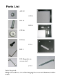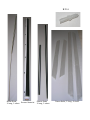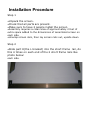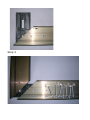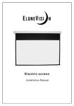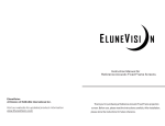
1
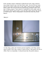
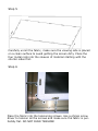
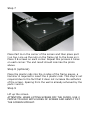
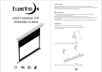
Elara Fixed Frame Series
Instruction Booklet
EluneVision Inc.
25 Thornton Trail
Dundas, Ontario
L9H 6X9
www.EluneVision.com
Parts List
A X 12
GX4
B X 12
HX4
C X 16
D X 16
IX4
EX1
F X (depends on
screen size)
JX4
Tools Required:
Philips Screwdriver, a Level for hanging the screen and hammer/rubber
mallet
KX4
Metal Rods,
Screen Material
2 long, 2 short
Plastic Rods
2 long, 2 short
Frame Rails, 2 long, 2 short
Installation Procedure
Step 1
•Unpack the screen.
•Check that all parts are present.
•Make sure to have 2 people install the screen
•Assembly requires a clean area of approximately 2 feet of
extra space added to the dimensions of assembled screen on
each side.
•Unwrap screen rails, then lay screen rails out, upside down
Step 2
•Slide part H(the L bracket) into the short frame rail, do
this 4 times on each end of the 2 short frame rails like
photo below:
each side.
Step 3
First unwrap screen material to determine how many tensioning screws need to go into the frame rails. You do this by looking at how many holes are on the sides of the screen material.
Then insert the correct amount tensioning screws(F part) into
the 4 frame pieces. Then insert 2 nuts(Part A) into each end of
the longer frame piece and 1 nut into the each end of the shorter frame piece. Once completed it should look like the photo
above.
Step 4
In this step, place all 4 frame pieces together, and then place
part D and C into the 4 holes in each corner. Use part E to do so.
After that is completed, it should look like the photo above.
Step 5
Carefully unroll the fabric, make sure the viewing side is placed
on a clean surface to avoid getting the screen dirty. Place the
four metal rods into the sleeves of material starting with the
shorter sides first.
Step 6
Place the fabric into the tensioning screws. Use a philips screw
driver to tension all the screws and make sure the fabric is perfectdly flat. DO NOT OVER TENSION!
Step 7
Place Part G on the corner of the screen and then place part
I on top. Line up the nuts on the frame rail to the holes on I.
Place 3 B screws on each corner. Repeat this process 4 times
on each corner. The end result should look like the photo
above.
Step 8 (optional)
Place the plastic rods into the 4 sides of the frame pieces, a
hammer is required to insert the 4 plastic rods. This step is not
required due to the fact that it does not increase the asthetics
of the screen. Spacing from the wall is already acheived by the
parts I and G.
Step 9
Lift up the screen.
ATTENTION: WHEN LIFTING SCREEN OFF THE FLOOR, USE 2
PEOPLE TO HOLD BOTH SIDES OF SCREEN AND GENTLY TILT
THE SCREEN UPRIGHT.
Step 10
Insert the plastic pipe into the drywall and then hang the
screen off the wall.
Warranty Information in Brief
Your EluneVision Product is backed by a 30 day, 100% satisfaction guarantee. If you are any way unsatisfied by this product, return it to us for
100% money back including your shipping fee.
Your EluneVision Product is also backed by a 1 year warranty against
manufacturing defects and failure of product under normal operation.
For detailed warranty information refer to www.EluneVision.com
EluneVision Inc.
25 Thornton Trail
Dundas, Ontario
L9H 6X9
www.EluneVision.com