1
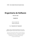
Altivar® 61 / 71
Profibus DPv1
User's manual
30072-452-99
Retain for future use.
VW3 A3 307 S371
Altivar® 61 / 71 Profibus DPv1
Table of Contents
30072-452-99
07/2009
Table of Contents
Hazard Categories and Special Symbols . . . . . . . . . . . . . . . . . . . . . . . . . . . . . . . . . . . . . . . . . . . . . . . . . . . . . . . . . . . . . . . . . 5
Before You Begin . . . . . . . . . . . . . . . . . . . . . . . . . . . . . . . . . . . . . . . . . . . . . . . . . . . . . . . . . . . . . . . . . . . . . . . . . . . . . . . . . . . . 6
Electrostatic Precautions . . . . . . . . . . . . . . . . . . . . . . . . . . . . . . . . . . . . . . . . . . . . . . . . . . . . . . . . . . . . . . . . . . . . . . . . . . . . . . 7
Bus Voltage Measurement . . . . . . . . . . . . . . . . . . . . . . . . . . . . . . . . . . . . . . . . . . . . . . . . . . . . . . . . . . . . . . . . . . . . . . . . . . . . . 7
Documentation Structure . . . . . . . . . . . . . . . . . . . . . . . . . . . . . . . . . . . . . . . . . . . . . . . . . . . . . . . . . . . . . . . . . . . . . . . . . . . . . . 8
Installation Manual. . . . . . . . . . . . . . . . . . . . . . . . . . . . . . . . . . . . . . . . . . . . . . . . . . . . . . . . . . . . . . . . . . . . . . . . . . . . . . . . . 8
Programming Manual . . . . . . . . . . . . . . . . . . . . . . . . . . . . . . . . . . . . . . . . . . . . . . . . . . . . . . . . . . . . . . . . . . . . . . . . . . . . . . 8
Communication Parameters Manual . . . . . . . . . . . . . . . . . . . . . . . . . . . . . . . . . . . . . . . . . . . . . . . . . . . . . . . . . . . . . . . . . . 8
Modbus®, CANopen, Ethernet, Profibus, INTERBUS, Uni-Telway™, FIPIO®, Modbus® Plus, DeviceNet™ Manuals. . 8
ATV58-58F/ATV71 Compatibility Manual . . . . . . . . . . . . . . . . . . . . . . . . . . . . . . . . . . . . . . . . . . . . . . . . . . . . . . . . . . . . . . . 8
Introduction . . . . . . . . . . . . . . . . . . . . . . . . . . . . . . . . . . . . . . . . . . . . . . . . . . . . . . . . . . . . . . . . . . . . . . . . . . . . . . . . . . . . . . . . . 9
Hardware Setup . . . . . . . . . . . . . . . . . . . . . . . . . . . . . . . . . . . . . . . . . . . . . . . . . . . . . . . . . . . . . . . . . . . . . . . . . . . . . . . . . . . . . 10
Receipt . . . . . . . . . . . . . . . . . . . . . . . . . . . . . . . . . . . . . . . . . . . . . . . . . . . . . . . . . . . . . . . . . . . . . . . . . . . . . . . . . . . . . . . . . 10
Installing the Card in the Drive . . . . . . . . . . . . . . . . . . . . . . . . . . . . . . . . . . . . . . . . . . . . . . . . . . . . . . . . . . . . . . . . . . . . . . 10
Connection to the Bus. . . . . . . . . . . . . . . . . . . . . . . . . . . . . . . . . . . . . . . . . . . . . . . . . . . . . . . . . . . . . . . . . . . . . . . . . . . . . 11
Recommendations. . . . . . . . . . . . . . . . . . . . . . . . . . . . . . . . . . . . . . . . . . . . . . . . . . . . . . . . . . . . . . . . . . . . . . . . . . . . . . . . 12
Configuration . . . . . . . . . . . . . . . . . . . . . . . . . . . . . . . . . . . . . . . . . . . . . . . . . . . . . . . . . . . . . . . . . . . . . . . . . . . . . . . . . . . . . . . 13
Configuring the Switches . . . . . . . . . . . . . . . . . . . . . . . . . . . . . . . . . . . . . . . . . . . . . . . . . . . . . . . . . . . . . . . . . . . . . . . . . . 13
Control Configuration . . . . . . . . . . . . . . . . . . . . . . . . . . . . . . . . . . . . . . . . . . . . . . . . . . . . . . . . . . . . . . . . . . . . . . . . . . . . . 15
Configuring Profibus Variables PZDs (Communication Scanner) . . . . . . . . . . . . . . . . . . . . . . . . . . . . . . . . . . . . . . . . . 18
Configuring Communication Interruption Management . . . . . . . . . . . . . . . . . . . . . . . . . . . . . . . . . . . . . . . . . . . . . . . . . 19
Configuring Monitored Parameters . . . . . . . . . . . . . . . . . . . . . . . . . . . . . . . . . . . . . . . . . . . . . . . . . . . . . . . . . . . . . . . . . . 20
Diagnostics . . . . . . . . . . . . . . . . . . . . . . . . . . . . . . . . . . . . . . . . . . . . . . . . . . . . . . . . . . . . . . . . . . . . . . . . . . . . . . . . . . . . . . . . 21
Monitoring the Address and Speed of the Bus. . . . . . . . . . . . . . . . . . . . . . . . . . . . . . . . . . . . . . . . . . . . . . . . . . . . . . . . . 21
LEDs . . . . . . . . . . . . . . . . . . . . . . . . . . . . . . . . . . . . . . . . . . . . . . . . . . . . . . . . . . . . . . . . . . . . . . . . . . . . . . . . . . . . . . . . . . . 21
Control-Signal Diagnostics. . . . . . . . . . . . . . . . . . . . . . . . . . . . . . . . . . . . . . . . . . . . . . . . . . . . . . . . . . . . . . . . . . . . . . . . . 22
Configuring Communication Interruption Management . . . . . . . . . . . . . . . . . . . . . . . . . . . . . . . . . . . . . . . . . . . . . . . . . 25
Card Conditions . . . . . . . . . . . . . . . . . . . . . . . . . . . . . . . . . . . . . . . . . . . . . . . . . . . . . . . . . . . . . . . . . . . . . . . . . . . . . . . . . . 25
Software Setup of DPv1 Messaging . . . . . . . . . . . . . . . . . . . . . . . . . . . . . . . . . . . . . . . . . . . . . . . . . . . . . . . . . . . . . . . . . . . . 26
Profibus DPv1 Protocol. . . . . . . . . . . . . . . . . . . . . . . . . . . . . . . . . . . . . . . . . . . . . . . . . . . . . . . . . . . . . . . . . . . . . . . . . . . . 26
Indirect Access (Using SLOT 1 Only) . . . . . . . . . . . . . . . . . . . . . . . . . . . . . . . . . . . . . . . . . . . . . . . . . . . . . . . . . . . . . . . . 26
Direct Access (Using the SLOT INDEX). . . . . . . . . . . . . . . . . . . . . . . . . . . . . . . . . . . . . . . . . . . . . . . . . . . . . . . . . . . . . . . 27
Software Setup of DPv0 Messaging . . . . . . . . . . . . . . . . . . . . . . . . . . . . . . . . . . . . . . . . . . . . . . . . . . . . . . . . . . . . . . . . . . . . 28
Output PZDs . . . . . . . . . . . . . . . . . . . . . . . . . . . . . . . . . . . . . . . . . . . . . . . . . . . . . . . . . . . . . . . . . . . . . . . . . . . . . . . . . . . . . 28
Input PZDs . . . . . . . . . . . . . . . . . . . . . . . . . . . . . . . . . . . . . . . . . . . . . . . . . . . . . . . . . . . . . . . . . . . . . . . . . . . . . . . . . . . . . . 29
PKW Aperiodic Service . . . . . . . . . . . . . . . . . . . . . . . . . . . . . . . . . . . . . . . . . . . . . . . . . . . . . . . . . . . . . . . . . . . . . . . . . . . . 30
© 2009 Schneider Electric USA All Rights Reserved
3
30072-452-99
07/2009
Altivar® 61 / 71 Profibus DPv1
Table of Contents
Software Setup Using PL7 . . . . . . . . . . . . . . . . . . . . . . . . . . . . . . . . . . . . . . . . . . . . . . . . . . . . . . . . . . . . . . . . . . . . . . . . . . . . 32
Example with SIMATIC Manager . . . . . . . . . . . . . . . . . . . . . . . . . . . . . . . . . . . . . . . . . . . . . . . . . . . . . . . . . . . . . . . . . . . . . . . 33
4
© 2009 Schneider Electric USA All Rights Reserved
Altivar® 71 Programming Guide
Hazard Categories and Special Symbols
30072-452-92
07/2009
Hazard Categories and Special Symbols
The following symbols and special messages may appear in this manual or on the equipment to warn of potential hazards or to call
attention to information that clarifies or simplifies a procedure.
A lightning bolt or ANSI man symbol in a “Danger” or “Warning” safety label on the equipment indicates an electrical hazard which,
as indicated below, can or will result in personal injury if the instructions are not followed.
The exclamation point symbol in a safety message in a manual indicates potential personal injury hazards. Obey all safety
messages introduced by this symbol to avoid possible injury or death.
Symbol
Name
Lightning Bolt
ANSI Man
Exclamation Point
DANGER
DANGER indicates an imminently hazardous situation which, if not avoided, will result in death or serious injury.
WARNING
WARNING indicates a potentially hazardous situation which, if not avoided, can result in death or serious injury.
CAUTION
CAUTION indicates a potentially hazardous situation which, if not avoided, can result in minor or moderate injury.
CAUTION
CAUTION, used without the safety alert symbol, indicates a potentially hazardous situation which, if not avoided, can result in
property damage.
Electrical equipment should be installed, operated, serviced, and maintained only by qualified personnel. No responsibility is
assumed by Schneider Electric for any consequences arising out of the use of this material.
The word drive as used in this manual refers to the controller portion of the adjustable speed drive as per the NEC.
© 2009 Schneider Electric USA All Rights Reserved
5
Altivar® 71 Programming Guide
Before You Begin
30072-452-92
07/2009
Before You Begin
Read and understand these instructions before performing any procedure on this drive. 1
DANGER
HAZARD OF ELECTRIC SHOCK, EXPLOSION, OR ARC FLASH
• Read and understand this manual before installing or operating the Altivar® 61 or 71 drive. Installation, adjustment, repair,
and maintenance must be performed by qualified personnel.
• The user is responsible for compliance with all national and local electrical code requirements with respect to grounding of all
equipment.
• Many parts in this drive, including the printed circuit boards, operate at the line voltage. DO NOT TOUCH. Use only electrically
insulated tools.
• DO NOT touch unshielded components or terminal strip screw connections with voltage present.
• DO NOT short across PA/+ and PC/– or across the DC bus capacitors.
• Before servicing the drive:
— Disconnect all power, including external control power that may be present.
— Place a “DO NOT TURN ON” label on all power disconnects.
— Lock all power disconnects in the open position.
— WAIT 15 MINUTES to allow the DC bus capacitors to discharge. Then follow the "Bus voltage Measurement" procedure
on page 7 to verify that the DC voltage is less than 42 V. The drive LED is not an indicator of the absence of DC bus
voltage.
• Install and close all covers before applying power or starting and stopping the drive.
Failure to follow these instructions will result in death or serious injury.
DANGER
UNINTENDED EQUIPMENT OPERATION
Before turning the drive on, or on exiting the configuration menus, check that the inputs assigned to the run command are
deactivated (at state 0) since they can cause the motor to start immediately.
Failure to follow these instructions will result in death or serious injury.
WARNING
DAMAGED DRIVE OR DRIVE ACCESSORY—UNINTENDED EQUIPMENT OPERATION
Do not install or operate any drive or drive accessory that appears damaged. The relays, inputs, or outputs of a damaged drive
may not operate in a normal manner, leading to unintended equipment operation.
Failure to follow these instructions can result in death, serious injury, or equipment damage.
WARNING
LOSS OF CONTROL
• The designer of any control scheme must consider the potential failure modes of control paths and, for certain critical control
functions, provide a means to achieve a safe state during and after a path failure. Examples of critical control functions are
emergency stop and overtravel stop.
• Separate or redundant control paths must be provided for critical control functions.
• System control paths may include communication links. Consideration must be given to the implications of unanticipated
transmission delays or failures of the link. 2
• Each implementation of an Altivar 61 or 71 drive must be individually and thoroughly tested for proper operation before being
placed into service.
Failure to follow these instructions can result in death, serious injury, or equipment damage.
1. The word drive as it is used in this manual refers to the controller portion of the adjustable speed drive as per the NEC.
2. For additional information refer to NEMA ICS 1.1 (latest edition), “Safety Guidelines for the Application, Installation, and Maintenance of Solid State Control” and to
NEMA ICS 7.1 (latest edition), “Safety Standards for Construction and Guide for Selection, Installation and Operation of Adjustable-Speed Drive Systems.”
6
© 2009 Schneider Electric USA All Rights Reserved
Altivar® 71 Programming Guide
Electrostatic Precautions
30072-452-92
07/2009
Electrostatic Precautions
CAUTION
STATIC SENSITIVE COMPONENTS
Circuit boards and option cards can be damaged by static electricity. Observe the electrostatic precautions below when handling
circuit boards or testing components.
Failure to follow these instructions can result in injury or equipment damage.
Observe the following precautions for handling static-sensitive components:
•
•
•
•
Keep static-producing material such as plastic, upholstery, and carpeting out of the immediate work area.
Store static-sensitive components in protective packaging when they are not installed in the drive.
When handling a static-sensitive component, wear a conductive wrist strap connected to the component or drive through a
minimum of 1 megohm resistance.
Avoid touching exposed conductors and component leads with skin or clothing.
Bus Voltage Measurement
DANGER
HAZARD OF ELECTRIC SHOCK, EXPLOSION, OR ARC FLASH
Read and understand the precautions in “Before You Begin” starting on page 6 before performing this procedure.
Failure to follow these instructions will result in death or serious injury.
The DC bus voltage can exceed 1,000 Vdc. Use a properly rated voltage-sensing device when performing this procedure. To
measure the DC bus voltage:
1. Disconnect all power.
2. Wait 15 minutes to allow the DC bus to discharge.
3. Measure the voltage of the DC bus between the PA/+ and PC/– terminals to ensure that the voltage is less than 42 Vdc.These
terminals are clearly labeled on each drive.
4. If the DC bus capacitors do not discharge completely, contact your local Schneider Electric representative. Do not repair or
operate the drive.
CAUTION
IMPROPER DRIVE OPERATION
• If no power is applied to the drive for a long period, the performance of its electrolytic capacitors will be reduced.
• Apply power to the drive every two years using the following procedure. Do not initially connect the drive directly to full line
voltage. Without a motor connected to the drive, gradually increase the voltage using an adjustable AC source connected
between drive terminals L1 and L2:
— 25% of rated voltage for 30 minutes
— 50% of rated voltage for 30 minutes
— 75% of rated voltage for 30 minutes
— 100% of rated voltage for at least 5 hours
• Check the drive operation before placing into service.
Failure to follow these instructions can result in injury or equipment damage.
© 2009 Schneider Electric USA All Rights Reserved
7
30072-452-92
07/2009
Altivar® 71 Programming Guide
Documentation Structure
Documentation Structure
Installation Manual
This manual describes:
• How to assemble the drive
• How to connect the drive
Programming Manual
This manual describes:
• The functions
• The parameters
• How to use the drive display terminal (integrated display terminal and graphic display terminal)
Communication Parameters Manual
This manual describes:
•
•
•
The drive parameters with specific information (addresses, formats, etc.) for use via a bus or communication network
The operating modes specific to communication (status chart)
The interaction between communication and local control
Modbus®, CANopen, Ethernet, Profibus, INTERBUS, Uni-Telway™, FIPIO®, Modbus® Plus,
DeviceNet™ Manuals
These manuals describe:
•
•
•
•
•
Connection to the bus or network
Configuration of the communication-specific parameters via the integrated display terminal or the graphic display terminal
Diagnostics
Software setup
The communication services specific to the protocol
ATV58-58F/ATV71 Compatibility Manual
This manual describes the differences between the Altivar 71 and the Altivar 58/58F. It explains how to replace an Altivar 58 or
58F, including how to replace drives communicating on a bus or network.
8
© 2009 Schneider Electric USA All Rights Reserved
Altivar® 61 / 71 Profibus DPv1
Introduction
30072-452-99
07/2009
Introduction
The Profibus DP communication card (catalog number VW3A A3 307 S371) is used to connect an Altivar® 61 / 71 drive to a
Profibus DPv1 bus.
This communication option card is supported by Altivar 61 firmware version V1.5 IE 13 and higher, and is only supported by
Altivar 71 firmware version V1.6 IE 19 and above. Specific versions of the Altivar 71 firmware are not supported.
Data is exchanged in order to make use of the following Altivar 61 / 71 functions:
•
•
•
•
•
Configuration
Adjustment
Control
Monitoring
Diagnostics
The card has a 9-pin female SUB-D connector for connection to the Profibus DPv1 bus. The connector and cable for connection to
the Profibus DPv1 bus must be ordered separately.
© 2009 Schneider Electric USA All Rights Reserved
9
Altivar® 61 / 71 Profibus DPv1
Hardware Setup
30072-452-99
07/2009
Hardware Setup
Receipt
•
Check that the card catalog number marked on the label is the same as that on the delivery note corresponding to the purchase
order.
•
Remove the option card from its packaging and check that it has not been damaged in transit.
Presentation
1 LEDs
2
Addressing switches, also used to adjust
the drive process data exchange mode
3 9-pin female SUB-D connector
Installing the Card in the Drive
DANGER
HAZARD OF ELECTRIC SHOCK, EXPLOSION, OR ARC FLASH
Read and understand the instructions on page 7 before performing this procedure.
Failure to follow these instructions will result in death or serious injury.
Before working on the drive, turn it off and wait 15 minutes to allow the DC bus to discharge. Then, read and follow the “Bus
Voltage Measurement” procedure on page 7.
Refer to the drive instruction bulletin included with the drive.
10
© 2009 Schneider Electric USA All Rights Reserved
Altivar® 61 / 71 Profibus DPv1
Hardware Setup
30072-452-99
07/2009
Connection to the Bus
Connector pinout
The transmission interface conforms to the RS 485 standard and is electrically isolated from the drive.
Pin 1
Pin 5
9-pin female SUB-D
Pin 9
Pin 6
Pin
Signal
Pin
Signal
Pin
1
Not connected
4
Not connected
7
2
Not connected
RxD/TxD-N
3
(Reception/Transmission -)
5
DGND (Ground)
8
6
VP (5 volts)
9
Signal
Not connected
RxD/TxD-P
(Reception/Transmission +)
Not connected
Connection accessories
Profibus DP bus connection elements
Description
Used
Connectors
With line terminator
490 NAD 911 03
Intermediate connection
490 NAD 911 04
Intermediate connection and connector port 490 NAD 911 05
Catalog number
Profibus DP bus connection cables
Description
Length
Catalog number
Profibus DP connection cables
100 m
400 m
TSX PBS CA 100
TSX PBS CA 400
Example of connection:
Profibus DP communication module: TSX-PBY100
Altivar 61 / 71
Altivar 61 / 71
TSX PREMIUM PLC
Intermediate
connectors
490 NAD 911 04
Connector with line
terminator 490 NAD 911 03
Profibus DP connection
cable TSX PBS CAp00
© 2009 Schneider Electric USA All Rights Reserved
11
Altivar® 61 / 71 Profibus DPv1
Hardware Setup
30072-452-99
07/2009
Recommendations
•
The user can select the data rate from a range of 9.6 kbps to 12 Mbps. This selection, made when starting up the network,
applies to the bus subscribers.
•
The maximum segment length is in inverse proportion to the data rate.
Data rate (kbps)
9.6
19.2
93.75
187.5
500
1500
3000
6000
12000
Distance/segment (m)
1200
1200
1200
1000
400
200
100
100
100
Repeaters can be used to cover greater distances.
•
•
•
•
12
The bus ends with a line terminator at each end of the segment.
Do not connect more than 32 stations per segment without a repeater, or more than 127 stations with a repeater.
Keep the bus away from the power cables (clearance of at least 30 cm).
If it is necessary for power cables to cross each other, be sure they cross at right angles.
© 2009 Schneider Electric USA All Rights Reserved
Altivar® 61 / 71 Profibus DPv1
Configuration
30072-452-99
07/2009
Configuration
Configuring the Switches
DANGER
UNINTENDED EQUIPMENT OPERATION
Before turning the drive on, or on exiting the configuration menus, check that the inputs assigned to the run command are
deactivated (at state 0) since they can cause the motor to start immediately.
Failure to follow these instructions can result in equipment damage.
NOTE: A new configuration of the switches (address and mode) will only be applied after the next power up of the drive.
Selecting the Operating Mode
The switch furthest to the left is used to determine the type of cyclic exchanges performed by the drive:
•
•
Switch 0 (OFF): Altivar® 61 / 71 mode
Switch 1 (ON): Altivar® 58 compatibility mode
This manual only describes Altivar 61 / 71 mode. To find out about Altivar 58 compatibility mode, refer to the ATV58-58F/ATV71
migration manual.
© 2009 Schneider Electric USA All Rights Reserved
13
Altivar® 61 / 71 Profibus DPv1
Configuration
30072-452-99
07/2009
Coding the Drive Address
An Altivar® 61 / 71 is identified on the bus by its address, coded between 0 and 126. The address corresponds to the binary
number given by position 0 (up/OFF) or 1 (down/ON) of the 7 switches on the right of the card. The least significant bits are on the
right.
The table below indicates the positions of the switches for the configurable addresses:
Addr.
Switches
Addr.
Switches
Addr.
Switches
Addr.
Switches
0
1
002
003
004
005
006
007
008
009
010
011
012
013
014
015
016
017
018
019
020
021
022
023
024
025
026
027
028
029
030
031
0000 0000
0000 0001
0000 0010
0000 0011
0000 0100
0000 0101
0000 0110
0000 0111
0000 1000
0000 1001
0000 1010
0000 1011
0000 1100
0000 1101
0000 1110
0000 1111
0001 0000
0001 0001
0001 0010
0001 0011
0001 0100
0001 0101
0001 0110
0001 0111
0001 1000
0001 1001
0001 1010
0001 1011
0001 1100
0001 1101
0001 1110
0001 1111
032
033
034
035
036
037
038
039
040
041
042
043
044
045
046
047
048
049
050
051
052
053
054
055
056
057
058
059
060
061
062
063
0010 0000
0010 0001
0010 0010
0010 0011
0010 0100
0010 0101
0010 0110
0010 0111
0010 1000
0010 1001
0010 1010
0010 1011
0010 1100
0010 1101
0010 1110
0010 1111
0011 0000
0011 0001
0011 0010
0011 0011
0011 0100
0011 0101
0011 0110
0011 0111
0011 1000
0011 1001
0011 1010
0011 1011
0011 1100
0011 1101
0011 1110
0011 1111
064
065
066
067
068
069
070
071
072
073
074
075
076
077
078
079
080
081
082
083
084
085
086
087
088
089
090
091
092
093
094
095
0100 0000
0100 0001
0100 0010
0100 0011
0100 0100
0100 0101
0100 0110
0100 0111
0100 1000
0100 1001
0100 1010
0100 1011
0100 1100
0100 1101
0100 1110
0100 1111
0101 0000
0101 0001
0101 0010
0101 0011
0101 0100
0101 0101
0101 0110
0101 0111
0101 1000
0101 1001
0101 1010
0101 1011
0101 1100
0101 1101
0101 1110
0101 1111
096
097
098
099
100
101
102
103
104
105
106
107
108
109
110
111
112
113
114
115
116
117
118
119
120
121
122
123
124
125
0110 0000
0110 0001
0110 0010
0110 0011
0110 0100
0110 0101
0110 0110
0110 0111
0110 1000
0110 1001
0110 1010
0110 1011
0110 1100
0110 1101
0110 1110
0110 1111
0111 0000
0111 0001
0111 0010
0111 0011
0111 0100
0111 0101
0111 0110
0111 0111
0111 1000
0111 1001
0111 1010
0111 1011
0111 1100
0111 1101
0111 1110
0111 1111
126
•
Addresses 0 and 1 are usually reserved for the Profibus DPv1 masters and must not be used to configure the Profibus DPv1
address on an Altivar 61 / 71.
•
It is not advised to use address 126, which is incompatible with SSA service (Set Slave Address) and with some network
configuration software (such as, Sycon).
Examples:
Address 23
Address 89
The address can be checked using the display terminal (see Diagnostics on page 22).
14
© 2009 Schneider Electric USA All Rights Reserved
Altivar® 61 / 71 Profibus DPv1
Configuration
30072-452-99
07/2009
Control Configuration
There are a number of possible configurations. For more information, refer to the programming and communication parameters
manuals. The configurations below are just some of the possibilities available.
Control via Profibus DPv1 in I/O profile
The run command and the speed reference come from Profibus DPv1.Control is in I/O profile.
Configure the following parameters:
Parameter
Value
Comment
Profile
I/O profile
The run command is obtained by bit 0 of the command word.
Reference 1 configuration
Network card
The reference comes from Profibus DPv1.
Command 1 configuration
Network card
The command comes from Profibus DPv1.
Configuration via the graphic display terminal or the integrated display terminal:
Menu
[1.6 - COMMAND] (/I7!)
Parameter
Value
[Profile] (CHCF)
[I/O profile] (IO)
[Ref. 1 chan] (Fr1)
[Com. opt card] (nEt)
[Cmd channel 1] (Cd1)
[Com. opt card] (D1I)
Control via Profibus DPv1 or via the terminals in I/O profile
The run command and the speed reference both come from Profibus DPv1 or the terminals. Input LI5 at the terminals is used to
switch between Profibus DPv1 and the terminals. Control is in I/O profile.
Configure the following parameters:
Parameter
Value
Comment
Profile
I/O profile
The run command is obtained by bit 0 of the command word.
Reference 1 configuration
Network card
Reference 1 comes from Profibus DPv1.
Reference 1B configuration
Analog input 1 on the terminals
Reference 1B comes from input AI1 on the terminals.
Reference switching
Input LI5
Input LI5 switches the reference (1 ↔ 1B).
Command 1 configuration
Network card
Command 1 comes from Profibus DPv1.
Command 2 configuration
Terminals
Command 2 comes from the terminals.
Command switching
Input LI5
Input LI5 switches the command.
Reference 1B is connected to the functions (summing, PID, etc.) that remain active, even after switching.
Configuration via the graphic display terminal or the integrated display terminal:
Menu
[1.6 - COMMAND] (CtL-)
Parameter
Value
[Profile] (CHCF)
[I/O profile] (IO)
[Ref. 1 chan] (Fr1)
[Com. card] (nEt)
[Cmd channel 1] (Cd1)
[Com. card] (nEt)
[Cmd channel 2] (Cd2)
[Terminals] (tEr)
[Cmd switching] (CCS)
[LI5] (LI5)
[1.7 APPLICATION FUNCT.] (FUn-)
[Ref. 1B chan] (Fr1b)
[AI1 ref.] (AI1)
[REFERENCE SWITCH.]
[Ref 1B switching] (rCb)
[LI5] (LI5)
© 2009 Schneider Electric USA All Rights Reserved
15
Altivar® 61 / 71 Profibus DPv1
Configuration
30072-452-99
07/2009
Control via Profibus DPv1 in Drivecom profile
The run command and the speed reference come from Profibus DPv1.
Control is in Drivecom profile.
Configure the following parameters:
Parameter
Value
Comment
Profile
Not Separate Drivecom profile
The run commands are in Drivecom profile, the command and the reference come
from the same channel.
Reference 1 configuration
Network card
The command comes from Profibus DPv1.
Configuration via the graphic display terminal or the integrated display terminal:
Menu
[1.6 - COMMAND] (CtL)
Parameter
Value
[Profile] (CHCF)
[Not Separate] (SIM) (factory setting)
[Ref. 1 chan] (Fr1)
[Com. card] (nEt)
Control via Profibus DPv1 or the terminals in Drivecom profile
The run command and the speed reference both come from Profibus DPv1 or the terminals. Input LI5 at the terminals is used to
switch between Profibus DPv1 and the terminals. Control is in Drivecom profile.
Configure the following parameters:
Parameter
Value
Comment
Profile
Not Separate Drivecom profile
The run commands are in the Drivecom profile, the command and the
reference come from the same channel.
Reference 1 configuration
Network card
Reference 1 comes from Profibus DPv1.
Reference 2 configuration
Analog input 1 on the terminals
Reference 2 comes from input AI1 on the terminals.
Reference switching
Input LI5
Input LI5 switches the reference (1 ↔ 2) and the command.
Configuration via the graphic display terminal or the integrated display terminal:
Menu
[1.6 - COMMAND] (CtL)
16
Parameter
Value
[Profile] (CHCF)
[Not Separate] (SIM)
[Ref. 1 chan] (Fr1)
[Com. card] (nEt)
[Ref. 2 chan] (Fr2)
[AI1 ref.] (AI1)
[Ref 2 switching] (rFC)
[LI5] (LI5)
© 2009 Schneider Electric USA All Rights Reserved
Altivar® 61 / 71 Profibus DPv1
Configuration
30072-452-99
07/2009
Control in Drivecom profile via Profibus DPv1 and reference switching at the terminals
The run command comes from Profibus DPv1. The speed reference comes either from Profibus DPv1 or from the terminals. Input
LI5 at the terminals is used to switch the reference between Profibus DPv1 and the terminals. Control is in the Drivecom profile.
Configure the following parameters:
Parameter
Value
Comment
Profile
Separate Drivecom profile
The run commands are in Drivecom profile, the command and the reference
can come from different channels.
Reference 1 configuration
Network card
Reference 1 comes from Profibus DPv1.
Reference 1B configuration
Analog input 1 on the terminals
Reference 1B comes from input AI1 on the terminals.
Reference switching
Input LI5
Input LI5 switches the reference (1 ↔ 1B).
Command 1 configuration
Network card
Command 1 comes from Profibus DPv1.
Command switching
Channel 1
Channel 1 is the command channel.
Reference 1B is connected to the functions (summing, PID, etc.) that remain active, even after switching.
Configuration via the graphic display terminal or the integrated display terminal:
Menu
Parameter
Value
[Profile] (CHCF)
[Separate] (SEP)
[Ref. 1 chan] (Fr1)
[Com. card] (nEt)
[Cmd channel 1] (Cd1)
[Com. card] (nEt)
[Cmd switching] (CCS)
[ch1 active] (Cd1)
[1.7 APPLICATION FUNCT.] (FUn-)
[Ref. 1B chan] (Fr1b)
[AI1 ref.] (AI1)
[REFERENCE SWITCH.]
[Ref 1B switching] (rCb)
[LI5] (LI5)
[1.6 - COMMAND] (CtL-)
© 2009 Schneider Electric USA All Rights Reserved
17
Altivar® 61 / 71 Profibus DPv1
Configuration
30072-452-99
07/2009
Configuring Profibus Variables PZDs (Communication Scanner)
PZDs are configured through the communication scanner. The 8 periodic output variables are assigned by means of parameters
nCA1 to nCA8. They are configured using the graphic display terminal via the [1.9 - COMMUNICATION] (COM-) menu and
[COM. SCANNER OUTPUT] (OCS-) submenu.
NOTE: [COM. SCANNER OUTPUT] (OCS-) submenu defines the data (parameters nCA1 to nCA8) from the PLC to the drive.
An nCAp parameter with a value of zero does not designate any parameter in the drive. These 8 words are described in the table
below:
Parameter name
Profibus variable
Default assignment
[Scan. Out1 address] (nCA1)
PZD1
Command word (CMD)
[Scan. Out2 address] (nCA2)
PZD2
Speed reference (LFRD)—in rpm
[Scan. Out3 address] (nCA3)
PZD3
Not used
[Scan. Out4 address] (nCA4)
PZD4
Not used
[Scan. Out5 address] (nCA5)
PZD5
Not used
[Scan. Out6 address] (nCA6)
PZD6
Not used
[Scan. Out7 address] (nCA7)
PZD7
Not used
[Scan. Out8 address] (nCA8)
PZD8
Not used
The 8 periodic input variables are assigned by means of parameters nMA1 to nMA8. They are configured using the graphic display
terminal via the [1.9 - COMMUNICATION] (COM-) menu and [COM. SCANNER INPUT] (ICS-) submenu.
NOTE: [COM. SCANNER INPUT] (ICS-) submenu defines the data (parameters nMA1 to nMA8) from the drive to the PLC.
An nMAp parameter with a value of zero does not designate any parameter in the drive. These 8 words are described in the table
below:
Parameter name
Profibus variable
Default assignment
[Scan. In1 address] (nMA1)
PZD1
Status word (ETA)
[Scan. In2 address] (nMA2)
PZD2
Output speed (RFRD)—in rpm
[Scan. In3 address] (nMA3)
PZD3
Not used
[Scan. In4 address] (nMA4)
PZD4
Not used
[Scan. In5 address] (nMA5)
PZD5
Not used
[Scan. In6 address] (nMA6)
PZD6
Not used
[Scan. In7 address] (nMA7)
PZD7
Not used
[Scan. In8 address] (nMA8)
PZD8
Not used
Example of configuring PZDs via the graphic display terminal:
RDY
NET
+0.00Hz
0A
RDY
COM. SCANNER INPUT
NET
+0.00Hz
0A
COM. SCANNER OUTPUT
Scan. In1 address
:
3201
Scan. Out1 address :
8501
Scan. In2 address
:
8604
Scan. Out2 address :
8602
Scan. In3 address
:
0
Scan. Out3 address :
0
Scan. In4 address
:
0
Scan. Out4 address :
0
Scan. In5 address
:
0
Scan. Out5 address :
0
Code
Quick
Code
Quick
Scan. In6 address
:
0
Scan. Out6 address :
0
Scan. In7 address
:
0
Scan. Out7 address :
0
Scan. In8 address
:
0
Scan. Out8 address :
0
WARNING
LOSS OF CONTROL
• All modifications to parameters nMA1, nMA8 or nCA1, and nCA8 must be made with the motor stopped.
• The master PLC program should be updated with these modifications.
Failure to follow these instructions can result in death, serious injury, or equipment damage.
18
© 2009 Schneider Electric USA All Rights Reserved
Altivar® 61 / 71 Profibus DPv1
Configuration
30072-452-99
07/2009
Configuring Communication Interruption Management
The response of the drive in the event of a Profibus DPv1 communication interruption can be configured.
RDY
NET
+0.00Hz
0A
COM. FAULT MANAGEMENT
Configuration can be performed using the graphic display terminal or the
integrated display terminal via the [Network fault mgt] (CLL) parameter in
the [1.8 - FAULT MANAGEMENT] (FLt-) menu
([COM. FAULT MANAGEMENT] (CLL-) submenu).
Network fault mgt
:
Freewheel
CANopen fault mgt
:
Freewheel
Modbus fault mgt
:
Freewheel
Code
Quick
The values of the [Network fault mgt] (CLL) parameter, which trigger a [Com. network] (CnF), are:
Value
Meaning
[Freewheel] (YES)
:
Freewheel stop (factory setting).
[Ramp stop] (rMP)
:
Stop on ramp.
[Fast stop] (FSt)
:
Fast stop.
[DC injection] (dCI)
:
DC injection stop.
The values of the [Network fault mgt] (CLL) parameter, which do not trigger a [Com. network] (CnF), are:
Value
Meaning
[Ignore] (nO)
:
Event ignored.
[Per STT] (Stt)
:
Stop according to configuration of [Type of stop] (Stt).
[fallback spd] (LFF)
:
Change to fallback speed, maintained as long as the detected fault persists and the run command has
not been removed.
[Spd maint.] (rLS)
:
The drive maintains the speed at the time the detected fault occurred, as long as the detected fault
persists and the run command has not been removed.
The fallback speed can be configured in the [1.8 – FAULT MANAGEMENT] (FLt-) menu using the [Fallback speed] (LFF) parameter.
© 2009 Schneider Electric USA All Rights Reserved
19
Altivar® 61 / 71 Profibus DPv1
Configuration
30072-452-99
07/2009
Configuring Monitored Parameters
Up to 4 parameters can be selected and their value displayed in the [1.2 - MONITORING] menu ([COMMUNICATION MAP]
submenu) on the graphic display terminal.
The selection is made via the [6 - MONITORING CONFIG.] menu ([6.3 - CONFIG. COMM. MAP] submenu).
Each parameter in the range [Address 1 select] …
[Address 4 select] can be used to select the parameter logic
address. An address at zero is used to disable the function. The
Communication Parameters instruction manual provided on the
CD-ROM that is included with the drive can be used to obtain logic
addresses.
In the example given here, the monitored words are:
•
Parameter 1 = Motor current (LCR): Logic address W3204;
signed decimal format
•
Parameter 2 = Motor torque (OTR): Logic address W3205;
signed decimal format
•
Parameter 3 = Last detected fault (LFT): Logic address W7121;
hexadecimal format
•
Disabled parameter: Address W0; default format: Hexadecimal
format
RDY
NET
+0.00Hz
0A
6.3 CONFIG. COMM. MAP.
Address 1 select
:
3204
Format address 1
:
Signed
Address 2 select
:
3205
Format address 2
:
Signed
Address 3 select
:
7121
Code
Quick
Format address 3
:
Hex
Address 4 select
:
0
Format address 4
:
Hex
One of the three display formats below can be assigned to each monitored word:
Format
Range
Terminal display
Hexadecimal
0000 … FFFF
[Hex]
Signed decimal
-32,767 … 32,767
[Signed]
Unsigned decimal
0 … 65,535
[Not signed]
NOTE: If a monitored parameter:
—has been assigned to an unknown address (such as, 3200)
—has been assigned to a protected parameter
—has not been assigned
the value displayed in the [COMMUNICATION MAP] screen will be "-----" (see “Control-Signal Diagnostics” on page 22).
20
© 2009 Schneider Electric USA All Rights Reserved
Altivar® 61 / 71 Profibus DPv1
Diagnostics
30072-452-99
07/2009
Diagnostics
Monitoring the Address and Speed of the Bus
From the graphic display terminal, select the [1.9 - COMMUNICATION] (COM-) menu ([PROFIBUS DP] (PbS-) submenu) to
display both parameters:
•
•
[Address] (Adrc): Drive address on the bus configured with the switches
[Bit rate] (bdr): Bus speed imposed by the Profibus DPv1 master
These parameters cannot be modified.
LEDs
1.1
1.2
1.3
1.4
1.5
The Profibus DPv1 card has two LEDs, ST and DX, visible through the window on the cover of the Altivar 61 / 71:
• The status of the Profibus DPv1 card is indicated by the red ST (status) LED: LED 2.1.
• The status of the Profibus DPv1 communication link is indicated by the green DX (data exchange) LED: LED 2.2.
ST
DX
2.1
2.2
2.3
2.4
2.5
The table below provides the meaning of the various states of these two LEDs:
Red ST LED Green DX LED
Description
(LED 2.1)
(LED 2.2)
Corrective action(s)
The card has been configured and its
parameters set correctly by the master.
The card is in Idle state, awaiting configuration.
Enter a value between 1 and 126 using the switches on the
option card.
The card is in Wait_Prm or Wait_Cfg state.
Check the connection to the Profibus DPv1 bus, start up the
PLC, and, if the drive has a communication card interruption
(CnF) [Com Network], reset it.
The card is in ILF [Internal Com Link] detected
fault mode.
Check the connection between the Profibus DPv1 card and
the drive. See page 25 for more information.
The card is in the "data exchange" state, and
data exchange is taking place.
No communication on the bus,
no data is being exchanged.
Check the connection to the Profibus DPv1 bus, start up the
PLC.
LED states
LED off
Slow flashing (0.5 s)
LED on
Quick flashing (0.1 s)
© 2009 Schneider Electric USA All Rights Reserved
21
Altivar® 61 / 71 Profibus DPv1
Diagnostics
30072-452-99
07/2009
Control-Signal Diagnostics
On the graphic display terminal, the [1.2 - MONITORING] menu ([COMMUNICATION MAP] submenu) can be used to display
control-signal diagnostic information between the Altivar 61 / 71 drive and the Profibus DPv1 master:
Active command channel
•
•
•
•
•
•
•
•
•
•
Value of the command word (CMD) from the active command channel
Active reference channel
Value of the reference from the active reference channel
Value of the status word
Values of four parameters selected by the user
In the [COM. SCANNER INPUT MAP] submenu: PZD input values
In the [COM SCANNER OUTPUT MAP] submenu: PZD output values
In the [CMD. WORD IMAGE] submenu: Command words from the channels
In the [FREQ. REF. WORD MAP] submenu: Frequency reference from the channels
Example of the display of communication diagnostic information
RUN
NET
+50.00Hz
80A
COMMUNICATION MAP
Command channel
:
Com. card
Cmd value
:
000FHex
Channel ref. active
:
Com. card
Frequency ref
:
500.0Hz
Status word
:
8627Hex
Code
Quick
W3204
:
53
W3205
:
725
W7132
:
0000Hex
W0
:
-----Hex
COM. SCANNER INPUT MAP
COM SCANNER OUTPUT MAP
CMD. WORD
IMAGE
FREQ. REF. WORD
MAP
MODBUS NETWORK DIAG
MODBUS HMI DIAG
CANopen MAP
PROG. CARD SCANNER
22
© 2009 Schneider Electric USA All Rights Reserved
Altivar® 61 / 71 Profibus DPv1
Diagnostics
30072-452-99
07/2009
Displaying the Command Word
The [Command channel] parameter indicates the active command channel.
The [Cmd value] parameter indicates the hexadecimal value of the command word (CMD) used to control the drive.
The [CMD. WORD IMAGE] submenu is used to display the hexadecimal value of the command word produced by Profibus DPv1:
•
Command word CMD3 .......... communication card channel .......... field [Com card cmd.]
Displaying the Frequency Reference
The [Channel ref. active] parameter indicates the active reference channel.
The [Frequency ref] parameter indicates the value (in 0.1 Hz units) of the frequency reference (LFR) used to control the drive.
The [FREQ. REF. WORD MAP] submenu is used to display the value (in 0.1 Hz units) of the speed reference produced by
Profibus DPv1:
•
Speed reference LFR3 .......... Profibus DPv1 channel .......... parameter [Com. card ref.]
Displaying the Status Word
The [Status word] parameter indicates the value of the status word (ETA).
Displaying Parameters Selected by the User
The four [W····] parameters indicate the value of the four words selected by the user.
The address and display format of these parameters can be configured in the [6 - MONITORING CONFIG.] menu
([6.3 - CONFIG. COMM. MAP] submenu) (see "Configuration" section on page 20).
The value of a monitored word equals "-----" if:
•
•
•
Monitoring has not been activated (address equals W0)
The parameter is write protected
The parameter is not known (such as, W3200)
© 2009 Schneider Electric USA All Rights Reserved
23
Altivar® 61 / 71 Profibus DPv1
Diagnostics
30072-452-99
07/2009
Displaying PZDs (Communication Scanner)
In the [1.2 - MONITORING] (SUP-) menu:
•
The [COM. SCANNER INPUT MAP] (ISA-) submenu is used to display the value of the 8 input PZDs (communication
scanner input parameters NM1 to NM8).
•
The [COM SCANNER OUTPUT MAP] (OSA-) submenu is used to display the value of the 8 output PZDs (communication
scanner output parameters NC1 to NC8).
Configuration of these periodic parameters is described in the "Configuration" section.
Example of displaying PZDs on the graphic display terminal:
RUN
NET
+50.00Hz
80A
RUN
COM. SCANNER INPUT MAP
NET
+50.00Hz
80A
COM SCANNER OUTPUT MAP
Com Scan In1 val.
:
34359
Com Scan Out1 val. :
15
Com Scan In2 val.
:
600
Com Scan Out2 val. :
598
Com Scan In3 val.
:
0
Com Scan Out3 val. :
0
Com Scan In4 val.
:
0
Com Scan Out4 val. :
0
Com Scan In5 val.
:
0
Com Scan Out5 val. :
0
Code
Quick
Code
Quick
Com Scan In6 val.
:
0
Com Scan Out6 val. :
0
Com Scan In7 val.
:
0
Com Scan Out7 val. :
0
Com Scan In8 val.
:
0
Com Scan Out8 val. :
0
In this example, only the first two parameters have been configured (default assignment).
[Com Scan In1 val.]
= [34343]
Status word = 34359 = 16#8637
V
Drivecom status "Operation enabled",
reverse operation, speed reached.
[Com Scan In2 val.]
=
Output speed = 600
V
600 rpm
Command word = 15 = 16#000F
V
"Enable operation" (Run) command
Speed reference = 598
V
598 rpm
[Com Scan Out1 val.]
[Com Scan Out2 val.]
24
=
=
[600]
[15]
[598]
© 2009 Schneider Electric USA All Rights Reserved
Altivar® 61 / 71 Profibus DPv1
Diagnostics
30072-452-99
07/2009
Configuring Communication Interruption Management
Profibus DPv1 communication interruptions are displayed by the red LED on the Profibus DPv1 card. In factory settings, a Profibus
DPv1 communication interruption triggers a [Com. network] (CnF) and a freewheel stop. The response of the drive in the event of
a Profibus DPv1 communication interruption can be changed (see “Configuring Communication Interruption Management” on
page 19):
•
•
Drive [Com. network] (CnF) (freewheel stop, stop on ramp, fast stop or DC injection stop).
No drive [Com. network] (CnF) (stop, maintain, fallback).
The interruption management is described in the user’s manual "Communication parameters", chapter "Communication
monitoring":
•
After initialization (power up), the drive checks that at least one of the command or reference parameters has been written once
via Profibus DPv1.
•
Then, if a Profibus DPv1 communication interruption occurs, the drive reacts according to the configuration (such as, stop,
maintain, and fallback).
The origin of the last Profibus DPv1 communication interruption can be displayed by the parameter [Com. network] (CnF):
Value
Description of the values of the parameter [Com. network] (CnF)
0
No interruption
1
Time out on the reception of the periodic variables addressed to the drive. This time out is adjustable by the network
configuration software.
2
Unsuccessful identification between the Profibus DPv1 card of the drive and the Profibus DPv1 master.
3
Unsuccessful identification of the Profibus DPv1 card of the drive (hardware related).
The parameter [Com. network] (CnF) is displayed on the display terminal (graphic only): [1.10 DIAGNOSTICS] (DGT-) menu,
[MORE FAULT INFO] (AFI-) submenu.
Card Conditions
The [Internal Com link] (ILF) appears under certain card conditions:
•
•
Hardware related on the Profibus DPv1 card itself.
Dialog related between the option card and the drive.
It is not possible to configure the behavior of the drive in the event of a [Internal Com link] (ILF) event, the drive stops in freewheel.
This type of event cannot be reset.
Two parameters display the origin of the last [Internal Com link] (ILF) events:
•
•
[Internal link fault 1] (ILF1) displays the value that occurred on option card no. 1 (directly mounted on the drive),
[Internal link fault 2] (ILF2) displays the value that occurred on option card no. 2 (mounted on the option card no. 1),
The parameter [Internal link fault 1] (ILF1) and [Internal link fault 2] (ILF2) are displayed on the display terminal (graphic only):
[1.10 DIAGNOSTICS] (DGT-) menu, [MORE FAULT INFO] (AFI-) submenu.
Value
Description of the values of the parameter Internal link fault 1] (ILF1) and [Internal link fault 2] (ILF2)
0
No interruption
1
Loss of internal communication with the drive
2
Potential hardware problem detected
3
Error in the EEPROM checksum
4
EEPROM–analysis needed
5
Flash memory–analysis needed
6
RAM memory–analysis needed
7
NVRAM memory–analysis needed
8
Improper analog input
9
Improper analog output
10
Improper logic input
11
Improper logic output
101
Unknown card
102
Improper exchange between the option card and the drive
103
Dialog time out between the option card and the drive
© 2009 Schneider Electric USA All Rights Reserved
25
Altivar® 61 / 71 Profibus DPv1
Software Setup of DPv1 Messaging
30072-452-99
07/2009
Software Setup of DPv1 Messaging
Profibus DPv1 Protocol
Data is exchanged according to the master-slave principle. Only the master can initialize communication. The slaves behave like
servers responding to requests from masters. Several masters can coexist on the same bus. In this case, the slave I/O can be read
by the masters. However, a single master has write access to the outputs. The number of data items exchanged is defined at the
time of configuration.
A GSD file contains the configuration information for the Altivar® 61/71 with Profibus DPv1. This file is used by the PLC during the
configuration phases. The GSD file is unique to the whole Altivar 61/71 range. It does not describe the drive parameters, just the
communication information. This file appears on the CD-ROM supplied with the drive.
The Profibus DPv1 card for Altivar 61/71 drives only supports supports types 3, 4, 5 and 8 PPO format (Parameter-Process
Data-Object) cyclic frames.
PKW length (word)
1
2
3
PZD length (word)
4
1
2
3
4
5
6
7
8
9
10
PPO type 1
PPO type 2
PPO type 3
PPO type 4
PPO type 5
PPO type 6
PPO type 7
PPO type 8
PPO cyclic frames contain the periodic variables that are used for 2 types of service:
•
•
I/O exchanges (PZD)
Aperiodic exchanges (PKW) for parameter setting, configuration and diagnostics
PKW aperiodic exchanges are included in the cyclic frames and do not require special frames. An aperiodic exchange is used to
read or write a parameter. The Altivar 61 / 71 PKW service does not conform to Profidrive.
Several types of DPv1 master can currently be used:
•
•
Some masters require the exclusive use of slot 1, which requires an indirect access mechanism.
Others allow the data to be accessed directly using direct access.
Indirect Access (Using SLOT 1 Only)
To use Profibus DPv1 messaging the following sequence must be used:
Step 1: The Profibus DPv1 master must first give the slave the modbus offset of the parameter to be read or written:
Example with ACC
(offset 9001)
Function
Slot
Index
Length
Data
Data
0x5F
0x01
0xE9
0x02
Offset
Offset
0x5F
0x01
0xE9
0x02
0x2329
Step 2 (read): The Profibus DPv1 master must give the length to be read starting from the offset indicated in step 1:
Example with ACC
(length 1 word: length = 0x2 bytes)
Function
Slot
Index
Length
0x5E
0x01
0xEA
<0x3C
0x5E
0x01
0xEA
0x02
Data
Data
The response to this request contains the data to be read.
26
© 2009 Schneider Electric USA All Rights Reserved
Altivar® 61 / 71 Profibus DPv1
Software Setup of DPv1 Messaging
30072-452-99
07/2009
Step 2 (write): The Profibus DPv1 master must give the value to be written at the offset indicated in step 1:
Function
Slot
Index
Length
Data
Data
0x5F
0x01
0xEA
0x02
Value
Value
0x5F
0x01
0xEA
0x02
Example with ACC
(write at 1.6 s)
0x0010
To check what offset has been configured for the slave, use this function:
Function
Slot
Index
Length
Data
Data
0x5E
0x01
0xE9
0x02
Offset
Offset
Function
MSB slot
LSB index
Length
Data
Data
0x5E
0x23
0x29
0x02
Data
Data
Direct Access (Using the SLOT INDEX)
Direct access is available from slot 2 on:
Read
Example with ACC
(offset 9001 = Ox2329)
The response to this request contains the data to be read:
Value read
Function
MSB slot
LSB index
Length
0x5E
0x23
0x29
0x02
Function
MSB slot
LSB index
Length
0x5F
0x23
0x29
0x04
Function
Slot
Index
Length
0xDF
0x80
0xXX
0xYY
Function
Slot
Index
Length
0xDE
0x80
0xXX
0xYY
Value
Write
Example with ACC
(offset 9001 = Ox2329)
Data
Data
0x0011
Irrespective of the type of access used (direct or indirect)
Read report:
Data
Data
0
Write report:
Data
Data
0
With event types:
0xXX - 0xYY
Type of event
0xC2 - 0x00
Resource
SAP not available (in use)
0xB7 - 0x00
Access
Incorrect length (= 0 or > 60)
0xA0 - 0x00
Application
Read unsuccessful (time out, etc)
© 2009 Schneider Electric USA All Rights Reserved
Meaning
27
Altivar® 61 / 71 Profibus DPv1
Software Setup of DPv0 Messaging
30072-452-99
07/2009
Software Setup of DPv0 Messaging
Output PZDs
The first eight bytes contain an aperiodic request (PKW) to write or read a parameter. The remaining 20 bytes contain the output
PZDs (written from the Profibus master), of which only PZD1 to PZD8 are significant.
1
2
3
4
5
6
7
8
9
10
PKW
PKE
0
15
16
R/W
17
19
20
21
22
12
13
14
PZD1
PZD2
PZD3
NC1
NC2
NC3
PWE
18
11
23
24
25
26
27
28
PZD4
PZD5
PZD6
PZD7
PZD8
PZD9
PZD10
NC4
NC5
NC6
NC7
NC8
Not used
Not used
PKW request:
PKE
Parameter logic address
RIW
Request code
0: No request
1: Read
2: Write
PWE
For a read request: Not used
For a write request: Parameter value
Cyclic control and adjustment parameters:
•
•
•
•
•
•
•
•
PZD1: Communication scanner output word 1 (NC1)
PZD2: Communication scanner output word 2 (NC2)
PZD3: Communication scanner output word 3 (NC3)
PZD4: Communication scanner output word 4 (NC4)
PZD5: Communication scanner output word 5 (NC5)
PZD6: Communication scanner output word 6 (NC6)
PZD7: Communication scanner output word 7 (NC7)
PZD8: Communication scanner output word 8 (NC8)
The default assignment of the periodic output data is:
•
•
•
PZD1 = Command word
PZD2 = Speed reference
PZD 3 to PZD 10 = Not used
1
2
3
4
5
6
7
8
9
PKW
PKE
15
16
0
R/W
17
18
PWE
19
20
21
22
10
11
12
13
14
PZD1
PZD2
PZD3
Command word
Speed
reference
Not used
23
24
25
26
27
28
PZD4
PZD5
PZD6
PZD7
PZD8
PZD9
PZD10
Not used
Not used
Not used
Not used
Not used
Not used
Not used
The assignment of PZDs is described in the “Configuring Profibus Variables PZDs (Communication Scanner)” on page 18.
How to display the value of the PZDs is described in “Displaying PZDs (Communication Scanner)” on page 24.
28
© 2009 Schneider Electric USA All Rights Reserved
Altivar® 61 / 71 Profibus DPv1
Software Setup of DPv0 Messaging
30072-452-99
07/2009
Input PZDs
The first eight bytes contain the response (PKW) to the aperiodic read/write request. The remaining 20 bytes contain the input
PZDs (read mode), of which only PZD1 to PZD8 are significant.
1
2
3
4
5
6
7
8
9
PKW
PKE
15
16
0
R/W/
N
17
18
PWE
19
20
21
22
10
11
12
13
14
PZD1
PZD2
PZD3
NM1
NM2
NM3
23
24
25
26
27
28
PZD4
PZD5
PZD6
PZD7
PZD8
PZD9
PZD10
NM4
NM5
NM6
NM7
NM8
Not used
Not used
PKW request
Parameter logic address
PKE
Response code
0: No request
1: Successful read report
R/W/N
2: Successful write report
7: Event report
For a successful request: Parameter value
For an incorrect request:
PWE
0: Incorrect address
1: Write access denied
Cyclic monitoring parameters:
•
•
•
•
•
•
•
•
PZD1: Communication scanner input word 1 (NM1)
PZD2: Communication scanner input word 2 (NM2)
PZD3: Communication scanner input word 3 (NM3)
PZD4: Communication scanner input word 4 (NM4)
PZD5: Communication scanner input word 5 (NM5)
PZD6: Communication scanner input word 6 (NM6)
PZD7: Communication scanner input word 7 (NM7)
PZD8: Communication scanner input word 8 (NM8)
The default assignment of the periodic input data is:
•
•
•
PZD1 = Status word (ETA)
PZD2 = Output speed (RFRD)
PZD 3 to PZD 10 = Not used
1
2
3
4
0
R/W
17
18
5
6
7
8
9
PKW
PKE
15
16
PWE
19
20
21
22
10
11
12
13
14
PZD1
PZD2
PZD3
Status word
Output speed
Not used
23
24
25
26
27
28
PZD4
PZD5
PZD6
PZD7
PZD8
PZD9
PZD10
Not used
Not used
Not used
Not used
Not used
Not used
Not used
The assignment of PZDs is described in the “Configuring Profibus Variables PZDs (Communication Scanner)” on page 18.
How to display the value of the PZDs in “Displaying PZDs (Communication Scanner)” on page 24.
© 2009 Schneider Electric USA All Rights Reserved
29
30072-452-99
07/2009
Altivar® 61 / 71 Profibus DPv1
Software Setup of DPv0 Messaging
PKW Aperiodic Service
The PKW service, consisting of PKE, R/W, R/W/N, and PWE, enables aperiodic access to Altivar 61 and 71 parameters in read
and write mode.
Output PKWs
PKE
Parameter logic address
R/W
0: No request
1: Read
2: Write
One-off read and write requests can be triggered continuously while R/W equals 1 or 2.
NOTE: Values other than 0, 1 and 2 should not be used. In particular, the values 16#0052 and 16#0057 must not be used, as
these are reserved for compatibility with the Altivar 58/58F.
PWE
If write: Value to be written
Input PKWs
PKE
Copies the output PKE value
R/W/N
0: No request
1: Correct read operation
2: Correct write operation
7: Read or write discrepancy
PWE
•
If correct read operation: Parameter value. This can be limited by the drive if the maximum value is exceeded by the write
operation.
•
•
If correct write operation: Value of the write PWE
If the read or write operation was not successful:
0: Incorrect address
1: Write operation refused
NOTE: The parameters in the output PZDs should not be changed by the PKW service.
Parameters linked to output PZDs should not be changed by the PKW service.
Example: The speed reference and the frequency reference.
30
© 2009 Schneider Electric USA All Rights Reserved
Altivar® 61 / 71 Profibus DPv1
Software Setup of DPv0 Messaging
30072-452-99
07/2009
Examples of PKW aperiodic exchanges
Aperiodic write operation: Acceleration time ACC (address 9001) = 10 s, unit 0,1s (values in hexadecimal format).
1
2
3
4
5
6
7
8
etc.
23
29
00
02
00
00
00
64
etc.
ACC = 10 s
Write request
Address 9001 = 2329h
The positive response is identical to the write request, aperiodic part (bytes 1 to 8).
Example of negative response:
1
2
3
4
5
6
7
8
etc.
23
29
00
07
00
00
00
0
etc.
0 (incorrect address)
Negative response
© 2009 Schneider Electric USA All Rights Reserved
31
Altivar® 61 / 71 Profibus DPv1
Software Setup Using PL7
30072-452-99
07/2009
Software Setup Using PL7
Correspondence Between Cyclic Data and PL7 PRO Words
In PL7, cyclic exchanges between the Profibus DPv1 master (such as, TSX Premium PLC + TSX PBY100 module) and the
Altivar 61 / 71 take the form of input words %IWxy.0.k and output words %QWxy.0.k, where "x" = number of the PLC rack and
"y" = location of the Profibus DPv1 module in the PLC rack.
Profibus
PKW
PL7 output word
Altivar 61 / 71
parameter
Profibus
Altivar 61 / 71
parameter
PL7 input word
%QWxy.0
PKE
%IWxy.0
PKE
%QWxy.0.1
R/W
%IWxy.0.1
R/W/N
%IWxy.0.2
Not used
%QWxy.0.2
Not used
%QWxy.0.3
PWE
PZD1
%QWxy.0.4
NC1
PZD2
%QWxy.0.5
PZD3
PZD4
PKW
%IWxy.0.3
PWE
PZD1
%IWxy.0.4
NM1
NC2
PZD2
%IWxy.0.5
NM2
%QWxy.0.6
NC3
PZD3
%IWxy.0.6
NM3
%QWxy.0.7
NC4
PZD4
%IWxy.0.7
NM4
PZD5
%QWxy.0.8
NC5
PZD5
%IWxy.0.8
NM5
PZD6
%QWxy.0.9
NC6
PZD6
%IWxy.0.9
NM6
PZD7
%QWxy.0.10
NC7
PZD7
%IWxy.0.10
NM7
PZD8
%QWxy.0.11
NC8
PZD8
%IWxy.0.11
NM8
PZD9
%QWxy.0.12
PZD9
%IWxy.0.12
PZD10
%QWxy.0.13
PZD10
%IWxy.0.13
Not used
Not used
Default configuration of the periodic variables
PL7 output
word
Profibus
PKW
Altivar 61/ 71 parameter
PL7 input
word
Profibus
PKE
%QWxy.0
PKE
%IWxy.0
R/W
%QWxy.0.1
R/W
%IWxy.0.1
Not
used
%IWxy.0.2
PWE
%IWxy.0.3
Not
used
%QWxy.0.2
PWE
%QWxy.0.3
PKW
PZD1
%QWxy.0.4
Command word (CMD)
PZD2
%QWxy.0.5
Speed reference (LFRD)
PZD3
%QWxy.0.6
PZD4
%QWxy.0.7
PZD4
%IWxy.0.7
PZD5
%QWxy.0.8
PZD5
%IWxy.0.8
PZD6
%QWxy.0.9
PZD7
%QWxy.0.10
PZD8
PZD9
PZD10
32
PZD1
%IWxy.0.4
Status word (ETA)
PZD2
%IWxy.0.5
Output speed (RFRD)
PZD3
%IWxy.0.6
PZD6
%IWxy.0.9
PZD7
%IWxy.0.10
%QWxy.0.11
PZD8
%IWxy.0.11
%QWxy.0.12
PZD9
%IWxy.0.12
%QWxy.0.13
PZD10
%IWxy.0.13
Not used
Altivar 61/ 71 parameter
Not used
© 2009 Schneider Electric USA All Rights Reserved
Altivar® 61 / 71 Profibus DPv1
Example with SIMATIC Manager
30072-452-99
07/2009
Example with SIMATIC Manager
Configuration example:
In the SIMATIC project:
•
•
•
Add the GSD file that corresponds to the VW3 A3 307 S371 card.
•
Write down the PLC memory address where ATV61 / 71 periodics are mapped (refer to the red circle in the figure above).
This address area is used to setup DPv1 messaging.
Add the ATV71-PROFIBUS-DPV1-Modular to the Profibus address configured by the switch on the card.
Select the correct PPO.
© 2009 Schneider Electric USA All Rights Reserved
33
Altivar® 61 / 71 Profibus DPv1
Example with SIMATIC Manager
30072-452-99
07/2009
Messaging Example by Indirect Access:
Select a function bloc "SFC58" dedicated for DPv1 writing (indirect access - slot 1) and complete the fields. Follow the instructions
given in the section Indirect access page 26.
LADR field must correspond to the PLC memory address where ATV61 / 71 periodics are mapped (16#100 corresponds to 256 in
decimal).
RECNUM field corresponds to the index (0XE9 ou 0XEA) in accordance with the indirect mechanism already described.
RECORD filed corresponds to the ATV61 / 71 memory offset.
Writing example
34
Reading example
© 2009 Schneider Electric USA All Rights Reserved
Altivar® 61/71 Profibus DPv1
User’s Manual
Schneider Electric USA
8001 Knightdale Blvd.
Knightdale, NC 27545
1-888-SquareD
(1-888-778-2733)
www.schneider-electric.us
Electrical equipment should be installed, operated, serviced, and maintained only by qualified
personnel. No responsibility is assumed by Schneider Electric for any consequences arising out of
the use of this material.
30072-452-99 07/2009
© 2009 Schneider Electric All Rights Reserved