1
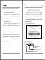
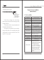
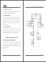
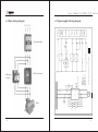
User's Manual for CM C - L S o f t S t a r t e r
Safety Precautions
(1) Hazardous voltage exists once the main loop power supply
is energized.
(2) Input ends 1L1, 3L2 and 5L3 are forbidden to be connected
to output ends 2T1, 4T2 and 6T3.
(3) Output ends 2T1, 4T2 and 6T3 of soft starter are forbidden
to be connected with compensating capacitor or
piezoresistor.
(4) When soft starter and frequency converter backup each
other, their output ends should be separated from each
other.
(5) Do not attempt to repair damaged components. Please
contact your supplier.
(6) The temperature of cooler is possibly high.
(7) Reverse power is forbidden to be fed on output ends of soft
starter.
(8) When soft starter is in a state of starting or stopping, high
voltage exists on output side.
1
User's Manual for CM C - L S o f t S t a r t e r
Table of contents
Foreword
6.5 Soft stop……………………………………………………20
7. Parameter and Description………………………………………21
1. Function and Feature of CMC-L Soft Starter……………………5
1.1 Function ………………………………………………………5
1.2 Feature………………………………………………………5
2. Receiving Inspection… … … … … … … … … … … … … … … … …7
3. Service Condition and Installation………………………………9
3.1 Service condition ……………………………………………9
3.2 Installation direction … … … … … … … … … … … … … … …10
3.3 Installation space ……………………………………………10
3.4 Circuit installation …………………………………………10
4. Circuit Connection………………………………………………10
4.1 Basic wiring schematic diagram……………………………10
4.2 Basic wiring diagram… … … … … … … … … … … … … … …12
4.3 Typical applied wiring diagram … … ……… … ……… … …13
4.4 Terminal description… … … … … … … … … … … … … … … 14
5. Display and Operation Description… … … … … … … … … … …16
5.1 View of panel………………………………………………16
7.1 Parameter……………………………………………………21
7.2 Function description…………………………………………22
8. Fault Detection and Troubleshooting……………………………22
8.1 List of fault code ……………………………………………22
8.2 Troubleshooting…………………………………………… 24
9. Maintenance………………………………………………………24
10. Description of Attached Table ……………………………… 25
Attached table 1 Specification Model and Selection of Accessories
………………………………………………………………………25
Attached table 2 Basic Setting for Different Application
………………………………………………………………………26
Attached table 3 Appearance of Soft Starter and Perforate dimension
………………………………………………………………………27
Attached table 4 Model Selection of Soft Starter……………………… 29
5.2 Function description of keys…………………………………16
5.3 Description of display status…………………………………17
6. Control Mode of Soft Starter ……………………………………18
6.1 Current-limiting start… … … … … … … … … … … … … … …19
6.2 Ramp current-limiting start…………………………………19
6.3 Voltage ramp start……………………………………………19
6.4 Free stop……………………………………………………20
2
3
User's Manual for CM C - L S o f t S t a r t e r
Chapter1 Function and Feature of
CMC-L Soft Starter
Foreword
1.1 Function
CMC-L motor soft starter is a new type motor starting and
Thank you for choosing CMC-L series motor soft starter
manufactured by Xi'an Spread Electric Co., Ltd. In order to bring
functions of soft starter into full play, please strictly operate and use
this soft starter in accordance with operating instructions and ensure
operator's safety. Please read through this manual before using this
device. When solutions for trouble that you encounter in using this
device are unavailable in this manual, please directly contact Xi'an
Spread Electric Co., Ltd. or agent and dealer. We will do our best to
protection device that is integrated with power electronic
technology, microprocessor and automatic control. This soft starter
is able to steadily start and stop motor without step change so as to
avoid mechanical or electric impact resulted from using
conventional starting modes such as direct starting, star-delta
starting and auto voltage reducing starting, and effectively reduce
starting current and distribution capacity for fear of more investment
on capacity expansion.
provide excellent service for you.
1.2 Feature
!
Multiple starting modes
Current-limiting start, ramp current-limiting start and voltage
ramp.start can meet the site requirements to the maximum extent and
realize the best starting effect.
!
High reliability
High performance microprocessor conducts digital processing
for signals in control system, avoiding the excessive adjustment to
4
5
User's Manual for CM C - L S o f t S t a r t e r
analog line so as to obtain the best precision and execution speed.
!
Powerful anti-interference performance
Chapter2 Receiving Inspection
Function and operation tests have been conducted on each soft
All external control signals adopt optoelectronic isolation and
starter before delivery. After receiving and unsealing the package,
are set with different anti-noise levels. The device is applicable for
please check according to the following steps. For any problem,
use in special industrial environment.
please contact your supplier immediately.
!
1.Check nameplate to confirm that the received model conforms
Optimized structure
to the one you ordered.
The unique compact structure is designed to be easily
(1) Nameplate description of soft starter
integrated into user's existing system, saving expenses for
restructuring of system.
CMC Series Motor Soft Starter
Product model: CMC-
!
Input voltage: 380VAC
Motor protection
Applicable motor:
KW
Use category: AC-53b
National standard: GB14048. 6-2008
Multiple motor protection functions such as over-current,
input/output phase-failure, short circuit of thyristor and overheat
protection can guarantee motor soft starter not to be damaged in case
XI'AN SPREAD ELECTRIC CO., LTD.
TEL.:029-85692700/85692711
of fault or incorrect operation.
!
Easy maintenance
(2) Model description
Service voltage class: e.g. 3
represents 380V
Power of applicable motor
Product code
6
7
User's Manual for CM C - L S o f t S t a r t e r
(3) Number description of soft starter
Chapter3 Service Condition
and Installation
L: Digital type
M: Digital intelligent type
SX: Chinese characters
display intelligent type
M2: Machine tool type
2. Check if there are damages such as sunken housing,
distortion, and loose of internal cables and connecting piece during
the transport of the device.
3.1 Service condition
Control power
AC110V—220V+15%
Three-phase power supply
AC380V, 660V, 1140V±30%
Nominal current
15A—1000A, totally 22 kinds of rated values.
Applicable motor
Stop mode
General squirrel cage asynchronous motor
Current-limiting soft start, voltage ramp start,
voltage ramp + current-limiting start
Free stop and soft stop
Logic input
Impedance 1.8KΩ,Power supply +15V
Ramp starting mode
3. Check if product certificate, warranty card, packing list and
user's manual are attached to the device.
4. This product will be guaranteed for repair according to
warranty card after delivery. After receiving this product, please
Protection function
Frequent or non-frequent start.
The number of starting is suggested
to be not more than 10 times per hour.
Phase failure, over current, short circuit,
SCR protection, over heat, etc.
Protection degree
IP00、IP20
Cooling method
Natural cooling or forced air cooling
Installation method
Wall mounting type
Starting frequency
carefully complete this warranty card and mail it back to Xi'an
Spread Co., Ltd. or your supplier.
Ambient condition
8
When altitude is above 2000m,
the capacity should be correspondingly
reduced.Ambient temperature:
-25~+45℃Relative humidity less
than 95%(20℃±5℃)No inflammable,
explosive and corrosive gas and no
conducting dust. Indoor installed
with good ventilation. Vibration less
than 0.5G.
9
User's Manual for CM C - L S o f t S t a r t e r
3.2 Installation direction
To ensure good atmospheric and cooling conditions for normal
KM
operation, soft starter should be vertically installed.
3.3 Installation space
Sufficient space should be arranged around the device for
FR
cooling. Please keep device certain distance away from wall for ease
QF
TA1
of maintenance (see attached table 3). If you need an air blower,
L1
please log on our website www.xichi.cn to download the size of
L2
3L2
relevant air blowers.
L3
5L3
N
X1/1
X1/2
3.4 Circuit installation
1L1
2T1
CMC—L
4T2
3M
6T3
Main loop adopts over-entering and down-out wiring method
and cables should be guaranteed with enough current-carrying
COM X1/3
Fault
capacity. Please see attached table 1 for selection of spare parts.
RUN X1/4
STOP X1/5
X1/8
X1/9
Bypass X1/6
Chapter 4 Circuit Connection
X1/7
X1/10
PE
4.1 Basic wiring schematic diagram
The terminals 1L1, 3L2 and 5L3 of soft starter are connected
L
with three-phase power supply and 2T1, 4T2 and 6T3 are connected
N
FU
KM
L
N
X1/11
220V
X1/12
to motor. When using a bypass contactor, it is can be controlled by an
in-built signal relay K2.
10
11
Motor
12
4T2
6T3
X1
3
4
5
5L3
1
X1 2
STOP
RUN
COM
KA1
8 X1 9
CMC-L
6 X1 7
CMC-L
KM
KA1
The control loop diagram is based on factory setting
Double nodes control
X1
3
4
5
Single node control
KA1
CMC-L soft starter
Main loop
2T1
CMC-L
3L2
A
SB1
11
CMC-L
12
AC220V
KA2
Control loop
Sb2
FR
QF1
Hl3
Hl2
Hl1
KA2
KA1
QF circuit breaker
FR
1L1
TA1
KM bypass
contactor
PV
QF
L1
N
Stop
indication
Operation
indication
Fault
indication
Bypass
control
Soft start/
stop control
Control
power
supply
Microdisconnection
4.2 Basic wiring diagram
KM
L1
L2
L3
N
User's Manual for CM C - L S o f t S t a r t e r
4.3 Typical applied wiring diagram
L1 L2 L3
13
User's Manual for CM C - L S o f t S t a r t e r
Note:
X1/1
1. The above diagram shows a single node control mode. When
Input terminal for
current detection
Connected with current
transformer
X1/3
COM
Common terminal of logic input
X1/4
External control
start terminal (RUN)
Start when X1/3 is short
-circuited with X1/4
X1/5
External control stop
terminal (STOP)
Stop when X1/3 breaks
with X1/5
Relay of bypass
output
When outputting effectively,
K21-K22 close, and contact
rating AC250V/5A,
DC30V/5A
Relay of fault
output
When outputting effectively,
K11-K12 close, and contact
rating AC250V/5A,
DC30V/5A
PE
Functional earthing
AC110V—AC220V
+15% 50/60Hz
Input terminal of control
power supply
connection point closes, soft starter starts, and when connection
X1/2
point opens, soft starter stops. It needs to note that with this wiring
method, the start-up operation through LED panel is invalid. The
terminals 3, 4 and 5 start/stop signal is a passive node.
PE grounding wire should be as short as possible and connected
to the nearest ground point away from soft starter. The appropriate
ground point should be on the mounting plate abutting against soft
starter, and the mounting plate should be grounded, which is
functional grounding rather than protective grounding.
3. The diameter of secondary side line of current transformer
Control
loop
should be no less than 2m m2.
X1/6
X1/7
4.4 Terminal description
CMC-L series soft starter has 12 external control terminals
X1/8
providing convenience for users to realize external signal control,
remote control and system control.
Terminal No.
X1/9
Name of terminal
Description
Input terminal for
AC power supply
Connected with three
-phase AC power supply
X1/10
1L1、3L2、5L3
Main
loop
X1/11
2T1、4T2、6T3
14
Output terminal
for soft start
Connected with three-phase
asynchronous motor
X1/12
15
User's Manual for CM C - L S o f t S t a r t e r
C
Chapter5 Display
and Operation Description
RUN
5.1 View of panel
STOP
ESC key
Confirm the altered parameter
data and escape from the parameter
items and parameter menu
Running key
This key can be used for running
operation when being effectively
operated, and at this time the
terminal 3 and 5 on the terminal
block X1 are short-circuited.
Stop key
This key can be used for stopping
operation when being effectively
operated. Pressing the stop key for
four seconds in the state of fault
can reset the current fault.
5.3 Description of display status
No. Symbol displayed
Enter key
Stop key
ESC key
Increasing key
Decreasing key
5.2 Function description of keys
16
Status description
Remark
1
State of rest
The device is in state
of rest
2
State of programming
It is allowed to view
and set parameters
3
State of running 1
The device is in state
of starting
Running key
Symbol
Item
Function description
4
State of running 2
The device is in state
of full voltage running
——
Enter key
Enter the parameter menu,
and confirm the data of
parameter items to be altered
5
State of running 3
The device is in state
of soft stopping
Increasing key
Increase parameter or data
Decreasing key
Decrease parameter items or data
6
State of fault
The device is in state
of fault
17
User's Manual for CM C - L S o f t S t a r t e r
Parameter
Chapter6 Control Mode of Soft Starter
CMC-L series soft starter has several starting modes including
P1
Item
Starting time
Range
Set value
Factory
default
0~60S
0
10
—
3
current-limiting start, ramp current-limiting start and voltage ramp
start, and several stopping modes including soft stop and free stop.
P3
Current-limiting (1.5~5)Ie
magnification
8-grade adjustable
Users can choose different starting and stopping modes based on
Note: “—” means that user can set based
on individual requirements.
different load and specific service conditions.
Voltage curve
U(I)
Current
limiting
State of full
voltage running
6.2 Ramp current-limiting start
Deceleration ramp
(optional)
Output voltage increases based on
Rapid ramp
Current curve
(optional)
Running current
Initial voltage
(optional)
linear characteristics in starting time
U(I)
Ue
that has been set, meanwhile, output
Acceleration
ramp (optional)
t
Characteristic Curve of Soft
Start/Stop Voltage (current)
6.1 Current-limiting start
When using current-limiting starting mode, the starting time is
Im
current increases at certain speed. When
starting current increases to clipped Ui
value Im, current holds constant till the
Ie
t
0
completion of start.
6.3 Voltage ramp start
set to zero. After soft starter receives starting command, output
voltage will quickly increase till output current reaches current
clipped value Im that has been set, and output current will stop to
increase. After motor runs and accelerates continuously for a period
of time, current begins to decrease and output voltage quickly
increases till full voltage output, then a starting process completes.
18
This starting mode is applicable to U ( I )
large inertia load. As for the situation
Ue
that requires higher stationarity of start,
it can largely reduce starting impact and
mechanical stress.
Ui
O
19
User's Manual for CM C - L S o f t S t a r t e r
Parameter
Item
Range
Set value
Factory
default
P0
Initial voltage (10%-70%)Ue
—
30%
P1
Starting time
—
10
0~60S
6.4 Free stop
Chapter7 Parameter and Description
7.1 Parameter
Param.
Item
Range
Factory
default
P0
Initial voltage
(10%-70%)Ue Full voltage
start enabled when setting to 99%
30%
P1
Starting time
0~60S current-limiting soft start
enabled when selecting 0 second
10
P2
Stopping time
0~60S Free stop enabled when
selecting 0 second
0
P3
Current-limiting
magnification
(1.5~5)Ie
adjustable
8-grade
(1.5~5)Ie
adjustable
8-grade
Free stopping mode is enabled when stopping time is set to
zero. After soft starter receives stopping command, it firstly lockout
the control relay of bypass contactor and consequently lockout the
output of thyristor on main loop. Motor stops freely according to
inertia load.
3
Parameter
Item
Range
Set value
Factory
default
P4
Overcurrent prot
ection in operation
P2
Stopping time
0~60S
0
0
P5
Undefined
parameter
—
—
P6
Selection
of control
0—terminal control
1—keyboard control
2—keyboard and terminal
control
2
6.5 Soft stop
When stopping time is not set to zero, stopping under condition
of full voltage is soft stop. To stop by this mode, soft starter firstly
disconnect bypass contactor and output voltage of soft starter
P7
SCR protection 0—SCR protection is allowed
1—SCR protection is forbidden
selection
decreases to zero within stopping time.
P8
Parameter
Item
Range
Set value
Factory
default
P2
Stopping time
0~60S
—
0
20
Double
ramp start
0—double ramp start is invalid
Non-zero—double ramp start is valid
Set value is the first starting
time (range: 0~60S)
1.5
0
0
21
User's Manual for CM C - L S o f t S t a r t e r
7.2 Function description
1.Check whether terminals 11 and 12 are connected.
2.Check whether control power supply is normal.
No display
The duration of starting time of parameter P1 can decide when
the starting torque is raised to the final torque. When the starting
Phase failure when
motor starts
Check whether each phase voltage of three-phase
power supply lacks phase, if any, troubleshoot it.
Temperature of
thyristor
1.Check whether installation environment of soft starter
has good ventilation and is vertically installed.
2.Check whether soft starter is directly shined by
sunshine.
3.Check whether cooler is overheated or overheat
protection switch is switched off.
4.Decrease frequency of starting.
5.Check whether control power supply is too low.
Starting failure
1.Check set value of each working parameter and
verify whether the set parameter values match the
actual parameter values of motor.
2.For starting failure (starting uncompleted in 80
seconds), check whether current-limiting
magnification is set too low or verify the
transformation ratio of transformer.
time is long, a smaller accelerating torque will be produced in the
course of starting motor, which is possible to realize soft
acceleration of motor for a long time. It is necessary to appropriately
choose the duration of starting time so as to make motor be able to
have soft acceleration until the rated speed is reached. When the
acceleration time ends before the completion of motor acceleration,
the torque will be limited to the set extreme torque in certain time.
Therefore, the starting time here represents the velocity of rotating
speed variation and doesnot completely equal the starting time of
motor.
Chapter8 Fault Detection and Troubleshooting
8.1 List of fault code
When protective functions of soft starter act, soft starter stops
immediately and display screen displays the current fault. User can
Short circuit on
1.Check whether bypass contactor is on position.
input and output
2.Check whether thyristor is brokendown or damaged.
ends of soft starter
1.Check whether output end of soft starter is properly
connected to the motor.
Motor connection
line opens (P7 set 2.Judge whether there is broken circuit inside motor.
3.Check whether thyristor is brokendown or damaged.
to 0 )
4.Check whether incoming line lacks phase.
conduct fault analysis according to fault description.
Display
State
description
Soft starter
in standby
Motor has no
response after
starting signal is
sent out
22
Troubleshooting
Current-limiting
function invalid
1.Check whether bypass contactor is on position.
2.Check whether thyristor is brokendown or
damaged.
1.Check whether terminals 3, 4 and 5 are connected.
2.Check whether control circuit is properly connected
and control switch is normal.
3.Check whether control power supply is too low.
Motor overcurrent
1.Check whether current transformer is connected to
terminals 1 and 2.
2.Check whether current-limiting protection setting
is correct.
3.Check whether the transformation ratio of current
transformer matches motor.
1.Check whether there is short circuit on connection
of output end of soft starter.
2.Motor overload or short circuit.
3.Check whether motor circuit lacks phase.
4.Check whether current transformer matches motor.
23
User's Manual for CM C - L S o f t S t a r t e r
8.2 Troubleshooting
Chapter10 Description of Attached Table
As fault has memory, after fault is cleared, press STOP key for
over 4 seconds to reset soft starter, making it recover to the ready
state for starting.
7.5
Model of Current tran Spec. of
Rated
line
bypass
sformer Primary
current (A) contactor
(copper line)
CMC-008-3
CJX4-25
6 mm
18
50\5
11
CMC-011-3
24
CJX4-32
50\5
10 mm 2
15
CMC-015-3
30
CJX4-32
100\5
16 mm 2
18.5
CMC-018-3
39
CJX4-40
100\5
16 mm 2
22
CMC-022-3
45
CJX4-50
100\5
16 mm 2
30
CMC-030-3
60
CJX4-63
100\5
25 mm 2
Use clean and dry brush to lightly brush away dust.
37
CMC-037-3
76
CJX4-80
200\5
25 mm 2
Use compressed air to blow away dust.
45
CMC-045-3
90
CJX4-95
200\5
35 mm 2
55
CMC-055-3
110
CJX4-115F
300\5
50 mm 2
75
CMC-075-3
150
CJX4-150F
300\5
70 mm 2
90
CMC-090-3
180
CJX4-185F
400\5
20×3
Copper row
110
CMC-110-3
218
CJX4-225F
500\5
20×3
Copper row
Use electric blower or electric furnace to dry it.
132
CMC-132-3
260
CJX4-265F
500\5
25×3
Copper row
Dehumidify power distribution room.
160
CMC-160-3
320
CJX4-330F
600\5
30×3
Copper row
egularly check the intactness of elements to ensure there are in
185
CMC-185-3
370
CJX4-400F
600\5
30×4
Copper row
220
CMC-220-3
440
CJX4-500F
800\5
30×4
Copper row
250
CMC-250-3
500
CJX4-500F
1000\5
40×4
Copper row
280
CMC-280-3
560
CJX4-630F
1000\5
40×4
Copper row
315
CMC-315-3
630
CJX4-630F
1500\5
40×5
Copper row
400
CMC-400-3
780
JWCJ20-800
1500\5
50×5
Copper row
470
CMC-470-3
920
JWCJ20-1000
1500\5
50×5
Copper row
530
CMC-530-3
1000
JWCJ20-1000
1500\5
50×6
Copper row
Chapter9 Maintenance
Dust: If there is too much dust, it may reduce the insulation
grade of soft starter and make it unable to work normally.
oisture condensation: If there is moisture condensation, it may
reduce the insulation grade of soft starter and make it unable to work
normally.
good condition.
Heck the cooling channel of soft starter for fear of being
blocked by sundries and dust.
Maintenance inspection must be made after all power
supplies of line side of soft starter are switched off.
24
Attached table 1 Specification Model and Selection of Accessories
Motor
(KW)
Model of
soft starter
2
25
User's Manual for CM C - L S o f t S t a r t e r
Centrifugal pump
20
6
6
3
Piston compressor
20
15
0
3
Lifting machine
30
15
6
3.5
Mixer
40
15
0
3.5
The standard configuration of soft starter does not contain
Crusher
30
15
6
3.5
bypass contactor and current detection transformer. Users
Screw compressor
20
15
0
3.5
may choose rational bypass contactor and current detection
Spiral conveyor
15
10
6
3.5
transformer (each soft starter requires one transformer)
Idling motor
20
10
0
2.5
according to the model and specification listed in above
Belt conveyor
20
15
10
3.5
table.
Heat pump
20
15
6
3
The selection of accessories is based on the current of
Auto ladder
20
10
0
3
controller when main power supply is AC660V, AC1140V.
Gas pump
20
10
0
2.5
Ordering instructions
Ø
To choose appropriate product, please provide your required
product model, specification, load conditions and
application conditions for supplier in ordering.
The selection of relevant current transformer and contactor
Attached table 3 Appearance of Soft Starter and
Perforate dimension
is based on the current of controller.
Accessories in above table are used for reference only.
(Unit: mm, with 380V as example)
Attached table 2 Basic Setting for Different Application
(for reference only)
Types of load
Initial
voltage
(%)
Ramp
Ramp
starting
stopping
time (sec.) time (sec.)
Current
limiting
ILIM
Propeller
20
10
0
2.5
Centrifugal fan
15
20
0
3.5
26
H
I
K
L
M
A
B
C
CMC-008~075 173
286
203
133
250
7
20
10
100
CMC-090~185 286
440
220
240
357
9
20
10
100
CMC-220~315 325
480
220
279
386
9
20
10
100
CMC-400~530 407
620
220
350
481
9
20
10
100
Model
G
27
User's Manual for CM C - L S o f t S t a r t e r
Products of 75KW and below
Products of 90KW and above
Attached table 4 Model Selection of Soft Starter
28
Note:Size F001:173×286×203
F003:325×480×220,
F004:407×620×220(W×H×L)
F002:286×440×220,
29
User's Manual for CM C - L S o f t S t a r t e r
30
31
32