1
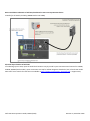
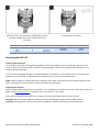
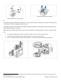
Dell UPS Site Preparation Guide, EMEA. Applies Dell Rackmount UPS Models, 3750W, 4200W, 5600W & 10kW Note: This document is for guidance only. Actual installation instructions and safety cautions are included within the UPS User’s Guide. Quick link to User’s Guides: http://dellups.com/support_download.asp > User Manuals and Publications. Site Preparation Checklist Installation site meets minimum environmental requirements. Ensured all required accessories have been ordered with the UPS. Electrical Preparation Required electrical supply is available. Scheduled an electrician to install the Dell UPS. Provided a copy of this preparation guide to the electrician. Made electrician aware of Hardwiring the UPS electrician’s checklist in the User’s Guide. Site Preparation: Physical Requirements for the Dell UPS UPS Model 3750W Rack 4200W Rack 5600W Rack 5600W Rack 10kW Rack UPS Technology Online Online Line Interactive Online Online Dimensions (mm, W x D x H) 4U, 438 x 790 x 171.5 4U, 438 x 790 x 171.5 4U, 438 x 790 x 171.5 4U, 438 x 790 x 171.5 5U, 438 x 823 x 214 Weight (installed, no battery) 65kg, 23kg 65kg, 23kg 72kg, 24kg 64kg, 24kg 110kg, 46kg EBM* for 3750W/4200W UPS n/a 3U, 438 x 735 x 127 61kg, n/a EBM* for all 5600W UPS n/a 4U, 438 x 735 x 171.5 66kg, n/a EBM* for 10kW n/a 3U, 438 x 737 x 127 80kg, n/a * EBM is an optional ‘external battery module’. Environmental Requirements for the Dell UPS Environmental Condition Suitable Range Temperature (Operation) Temperature (Storage, 24hr) Temperature (Long-term Storage) Relative Humidity Elevation (Operation) 0 - 40C (32 - 104F) -15 - 60C (5 - 140F) - 15 - 45C (5 - 113F) 0 - 95% (non-condensing) 0 - 3048m (0 - 10,000ft) Elevation (Storage) 0 - 15,340m (0 - 50,000ft) Heat Output for the Dell UPS UPS Model 3750W Rack UPS Technology Online Heat Loss, Watts / BTU (normal mode) 188 / 640 Dell UPS Site Preparation Guide, EMEA (230V) Heat Loss, Watts / BTU (battery mode) 375 / 1281 Revision 2, December 2012 4200W Rack 5600W Rack 5600W Rack 10kW Rack Online Line Interactive Online Online 210 / 717 280 / 956 390 / 989 412 / 1420 420 / 1434 560 / 1921 420 / 1433 754 / 2600 Optional accessories for Dell UPS Optional Accessory Importance Purpose & Use External Battery Module (EBM) Network Management Card (NMC) Environmental Monitoring Probe (EMP) Optional Recommended 32 Amp, 3m (non-locking) 1 Electrical Input Cord Highly Recommended Increases the battery runtime (autonomy) by approximately 3 times Improves communication with >1 server and is mandatory for virtualization Measures rack temperature and humidity (plus 2 x relay contacts). Requires network management card. Data rolls up into UPS Management software. UPS input cable pack providing a 3m cord with IEC309 32A (IEC60309 332P6S, non-locking, IP44 type) Commando plug. Also includes plastic stuffing gland (strain relief). Recommended Rack Preparation: Rack Requirements for the Dell UPS Dell Rack UPS are suitable for installation into 19” 4-post racks. Reserve space for UPS and EBM at bottom of rack. Rack types supported are: EIA/ECA-310-E (includes Dell and other common rack suppliers); and, support 4-post square or round (non-threaded) type holes. If round hole, use rack with 7.0mm diameter (unthreaded). The Dell rack UPS and rack EBM include ReadyRails with a minimum retraction of 517 mm (20.35") and maximum extension of 783 mm (30.8"). Electrical Preparation: Electrical Requirements for the Dell UPS UPS Model UPS Technology Input Voltage (VAC) 3750W Rack 4200W Rack 5600W Rack 5600W Rack 10kW Rack Online Online Line Interactive Online Online 208, 220, 230, 240 208, 220, 230, 240 208, 220, 230, 240 208, 220, 230, 240 Power Draw (standby) 186W 210W 224W 143W 60W Overcurrent Protection 25 Amp 1-phase 30 Amp 1-phase 32 Amp 1-phase 32 Amp 1-phase 63 Amp 1-phase Minimum Wire Size (Live Neutral/Ground) 2 5.26 / 5.26 mm 2 5.26 / 5.26 mm 2 8.36 / 5.26 mm 2 8.36 / 5.26 mm 2 21.14 / 8.36 mm 208, 220, 230, 240 Note: Overcurrent protection should be ‘slow-break’, suitable for devices with a high inrush current. Normally this should be a fuse or circuit breaker with a Type-C or Type-3 rating. Electrical Requirements for the REPO Switch (Remote Emergency Power Off) REPO is used to shut down the UPS from a distance. For example, this feature can be used for shutting down the load and the UPS by thermal relay, in the event of room over-temperature. When REPO is activated, the UPS shuts down the output and all its power converters immediately. The UPS logic power remains on to issue an alarm. 1 Supported UPS are 3750W, 4200W (Online) and 5600W (Line Interactive) models. 5600W Online and 10kW Online UPSs do not have an input cord option. Dell UPS Site Preparation Guide, EMEA (230V) Revision 2, December 2012 The REPO feature shuts down the protected equipment immediately and does not follow the orderly shutdown procedure initiated by any power management software. Any devices that are operating on battery power are also shut down immediately. When the REPO switch is reset, the equipment will not return to utility or battery power until the UPS is manually restarted. There are two REPO ports on each UPS in order to support cascaded REPO functionality. This allows a single cable to be cascaded between multiple Dell UPS, eliminating the need for a dedicated REPO cable for each UPS & simplifying installation. The REPO contacts are normally open. Wire Function Terminal Wire Size Rating Remote Emergency Power Off (REPO) 4-0.32mm (12-22 AWG) 2 Suggested Wire Size 2 0.82mm (18 AWG) WARNING: The REPO circuit is an IEC 60950 safety extra low voltage (SELV) circuit. This circuit must be separated from any hazardous voltage circuits by reinforced insulation. CAUTION: The REPO must not be connected to any utility connected circuits. Reinforced insulation to the utility is required. The REPO switch must have a minimum rating of 24Vdc and 20 mA and be a dedicated latching-type switch not tied into any other circuit. The REPO signal must remain active for at least 250ms for proper operation. NOTE: For Europe, the emergency switch requirements are detailed in Harmonized document HD-384-48 S1, “Electrical Installation of the Buildings, Part 4: Protection for Safety, Chapter 46: Isolation and Switching.” NOTE: The pins must be open to keep the UPS running. If the UPS shuts down because the REPO connector pins are shorted, restart the UPS by reopening the REPO connector pins and turning on the UPS manually. Maximum resistance in the shorted loop is 10 ohm. NOTE: Always test the REPO function before applying your critical load to avoid accidental load loss. Electrical Wiring, Basic Installation Schematics Basic Installation Schematic of Dell UPS using optional 32 Amp, non-locking, power input cord. Suitable for all models except 5600W Online and 10kW Dell UPS Site Preparation Guide, EMEA (230V) Revision 2, December 2012 Basic Installation Schematic of Dell UPS, hardwired to overcurrent protection device Suitable for all models (including 5600W Online and 10kW) Electrical input location of Dell UPS If hardwiring input to UPS, input terminal block locations vary by model. Input connection exits bottom for 3750W, 4200W, 5600W (both models). Input connection exits top for 10kW. Diagrams show back (rear) of each UPS model. Microsoft® Visio stencils for Dell UPS are available at http://dellups.com/support_download.asp > Support FAQ. Dell UPS Site Preparation Guide, EMEA (230V) Revision 2, December 2012 Electrical input top entry 3,750W REPO IN REPO OUT REPO OUT OFF EXTENDED BATTERY 288 V 40 A REPO IN 20A 250Vac CIRCUIT BREAKER LS2 Use Copper Conductor Only. 15A 250Vac CIRCUIT BREAKER AC INPUT 230V OFF LS1 LS2 OUTPUT 250V~20A CIRCUIT BREAKER 250V~20A OUTPUT 250V~20A Not For Current Interrupting. OFF CIRCUIT BREAKER 250V~20A OFF CIRCUIT BREAKER 250V~20A OFF OFF CIRCUIT BREAKER 250V~20A OUTPUT 250V~20A L2-US L1-US N-EU N-EU OUTPUT 250V~20A LS1 BATT.EXT 192V 30A Refer to the instruction manual for the tightening torque. USE COPPER CONDUCTOR ONLY. INPUT 208-240V~ REFER TO THE INSTRUCTION MANUAL FOR TIGHTENING TORQUE Electrical input bottom entry 10kW WW Blades 4,200W REPO IN REPO OUT 20A 250Vac CIRCUIT BREAKER OFF Electrical input top entry OFF LS1 Use Copper Conductor Only. EXTENDED BATTERY 288 V 40 A REPO IN 15A 250Vac CIRCUIT BREAKER AC INPUT 230V REPO OUT OFF Not For Current Interru -pting. LS2 BATT.EXT 192V 30A Refer to the instruction manual for the tightening torque. Electrical input bottom entry OUTPUT 250V~32A LS1 OUTPUT 250V~20A CIRCUIT BREAKER 250V~32A OFF OFF CIRCUIT BREAKER 250V~20A L2-US L1-US N-EU N-EU OFF CIRCUIT BREAKER 250V~32A OUTPUT 250V~32A LS2 USE COPPER CONDUCTOR ONLY. INPUT 208-240V~ REFER TO THE INSTRUCTION MANUAL FOR TIGHTENING TORQUE 5,600W Line Interactive 10kW IEC INTL 20A 250VAC CIRCUIT BREAKER OFF OFF REPO IN 5,600W Online REPO OUT LS1 Use Copper Conductor Only. 15A 250VAC CIRCUIT BREAKER AC INPUT 230V USE COPPER CONDUCTOR ONLY. INPUT 220-240V~ OFF Not For Current Interru -pting. OUTPUT 220-240V~ 20A CIRCUIT BREAKER 250VAC 20A BATT.EXT 216V 30A LS2 Refer to the instruction manual for the tightening torque. BATT.EXT 216V 30A OUTPUT 220-240V~ 15A Refer to the instruction manual for the tightening torque. Electrical input bottom entry REPO OUT CIRCUIT BREAKER 250VAC 15A REPO IN LS1 LS2 Electrical input bottom entry Overcurrent Protection Devices: All Dell UPS Rack Mount Models (except 5600W Online and 10kW): In all cases the installation should include a dedicated electrical branch circuit with a 2-pole overcurrent protection device. The breaker should be wall-mounted and accessible to the operator. 5600W Online and 10kW UPS: The 5600W online and 10kW UPS does not have an automatic protection device against current backfeed. Dell recommends installing an external isolating device (see illustration below). After the device is installed, you must add a warning label with the following wording or the equivalent on the external AC contactor: “RISK OF VOLTAGE BACKFEED. Isolate the UPS before operating on this circuit, then check for hazardous voltage between all terminals.” Dell UPS Site Preparation Guide, EMEA (230V) Revision 2, December 2012 The following table lists approved AC contactors that can be used as backfeed protection devices for 5600W Online. Manufacturer Type Rating Moeller GMBH Tianshui Electrical Aparatus Co. Ltd (E203071) LS Industrial Systems Co., Ltd. (E108780) DILM(C)32-10 GSC1(CJX4-d)-4011 GMC(D)-32 600 V, 40A 220-240 Vac, 42 FLA 600 Vac, 45A The following table lists approved AC contactors that can be used as backfeed protection devices for 10kW. Manufacturer Type Rating ABB France (E12527) A75-30 Tianshui Electrical Aparatus Co. Ltd (E203071) Tianshui Electrical Aparatus Co. Ltd (E203071) GSC1(CJX4-d)-6511 GSC1(CJX4-d)-8011 220-240V, 105A 25 HP at 208V, 30HP at 240V 220-240 Vac, 68A 25HP 220-240 Vac, 80A 30HP Optional 32 Amp, non-locking, 1phase, 3m, UPS Input Cord Kit If you ordered the optional 32 Amp, non-locking, input cord kit refer to the below drawings for advice on fitting the cable: Step 1: Remove the cover-plate from the rear of the UPS to access rear-plate terminals and cable access port Dell UPS Site Preparation Guide, EMEA (230V) Step 2: Remove the back (side nearest cable bare ends) of the plastic stuffing gland from the input cord kit Revision 2, December 2012 Step 3: Thread the input cord through the UPS backplate and secure with the plastic stuffing gland. Ensure you leave enough free cord to connect to the UPS terminals. Wire Colour Green/Yellow Stripe Blue Brown Terminal Position G N L Step 4: Secure the bare cable ends to the UPS terminals & replace the cover-plate. UPS Wire Function Input Ground Neutral In Line (Live) In Terminal Wire Size Rating 2 5.26-16mm (10-6AWG) Tightening Torque 2.26Nm (20 lb in) Receiving the Dell UPS Inspecting the Equipment If any equipment has been damaged during shipment, keep the shipping cartons and packing materials for the carrier or place of purchase and file a claim for shipping damage. If you discover damage after acceptance, file a claim for concealed damage. To file a claim for shipping damage or concealed damage: 1) File with the carrier within 15 days of receipt of the equipment; 2) Send a copy of the damage claim within 15 days to your service representative. NOTE: Check the battery recharge date on the shipping carton label. If the date has passed and the batteries were never recharged, do not use the UPS. Contact your service representative. Unpacking the Dell UPS Remove all parts before beginning the installation. For a complete list of “what’s in the box” either refer to the user guide or visit www.dellups.com -> Configure UPS –> List All UPS -> Your model. Note that for some Dell UPS models the rack-mount rails may be packed below the UPS in the box. CAUTION: Refer to the user guide for complete instructions including important Health & Safety advice. CAUTION: This equipment is heavy; refer to the user guide for advice on unpacking and safe installation. Dell UPS Site Preparation Guide, EMEA (230V) Revision 2, December 2012 Actual carton may vary by model Actual contents may vary by model Installing the Dell UPS into the rack: Install the ReadyRails followed by the UPS chassis. Finally install the battery modules into the UPS chassis & connect the DC leads. Finish by installing the UPS front panel. Install the optional external battery module (EBM), Network Management Card (NMC), Environmental Monitoring Probe (EMP) and PDU(s)2, if ordered. Note: The Dell UPS equipment is heavy. Refer to the user guide for complete guidance on safety. Some key points are: You should typically place the UPS at the bottom of the rack for a lower centre of gravity Extend the rack stabilization feed during installation to prevent the rack tipping Ensure you follow health & safety recommendations for working with heavy & electrical equipment 2 Dell 16 Amp and 32 Amp PDUs can be plugged into Dell UPS. Dell 10kW UPS model with 2 x 32A outlets is tested with Dell 32 Amp PDU types for fit. Dell UPS Site Preparation Guide, EMEA (230V) Revision 2, December 2012