1
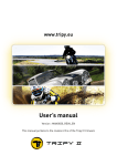
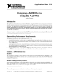
01
PLANET ECLIPSE: GEO CS1
USER MANUAL / ENGLISH
GEO:CS1
.68 CAL
02
WARNINGS
READ CAREFULLY BEFORE USE
!
THE PLANET ECLIPSE CS1 IS NOT A TOY. PAINTBALL
SAFETY RULES MUST BE FOLLOWED AT ALL TIMES.
!
areless or improper use of the CS1, including failure to follow
C
instructions and warnings within this User Manual could cause
serious injury or death.
!
Do not remove or deface any warnings attached to the CS1.
!
aintball industry standard eye/face/ear and head protection
P
designed specifically to stop paintballs and meeting ASTM standard
F1776 (USA) or CE standard (Europe) must be worn by the user and
any person within range. Proper protection must be worn during
assembly, cleaning and maintenance.
!
Always fit a barrel-blocking device to the CS1 when not in use.
!
Always remove paintballs from the CS1 when not in use.
!
Do not field strip or remove any parts while the marker is
pressurised.
!
o not pressurise the CS1 without all the components of the marker
D
correctly installed, as high-pressure gas may be emitted.
!
Do not fire the CS1 without the bolt correctly installed.
!
Never put your finger or any foreign objects into the paintball feed
tube of the CS1.
!
Never allow pressurised gas to come into contact with any part of
your body.
!
Hearing protection should be worn.
!
Never shoot at a person who is not wearing proper protection.
!
!
ever look directly into the barrel of the marker. Accidental
N
discharge into the eyes may cause permanent injury or death.
Never look into the barrel or breech area of the CS1 whilst the
marker is switched on and able to fire.
Always remove the first stage regulator and relieve all residual gas
pressure from the CS1 before disassembly.
!
Always remove the first stage regulator and relieve all residual gas
pressure from the CS1 for transport and storage.
!
Always follow guidelines given with your first stage regulator for safe
transportation and storage.
!
Keep the CS1 switched off until ready to shoot.
!
Treat every marker as if it is loaded and ready to fire.
!
Always store the CS1 in a secure place.
!
he electronic On/Off button is the marker’s disabling device, also
T
known as a safety. Always switch off the marker when not in use.
!
Observe all local and national laws, regulations and guidelines.
GEO:CS1
03
WARNINGS
READ CAREFULLY BEFORE USE
!
Persons under 18 years of age must have adult supervision when
using or handling the CS1.
!
Use only professional paintball fields where codes of safety are
strictly enforced.
!
se compressed air/nitrogen only. Do not use any other
U
compressed gas or pressurised liquid including CO2.
!
lways follow instructions, warnings and guidelines given with any
A
first stage regulator you use with the CS1.
!
Use 0.68 inch calibre paintballs only.
!
Always measure your marker’s velocity before playing paintball,
using a suitable chronograph.
!
Never shoot at velocities in excess of 300 feet (91.44 metres) per
second, or at velocities greater than local or national laws allow.
!
Any installations, modifications or repairs should be carried out by
a qualified individual at a licensed and insured paintball facility.
This User Manual is in English.
It contains important safety guidelines and
instructions. Should you be unsure at any
stage, or unable to understand the contents of
this manual you must seek expert advice.
Le mode d’emploi est en Anglais.
Il contient des instructions et mesures de
sécurité importantes. En cas de doute, ou
s’il vous est impossible de comprendre le
contenu du monde d’emploi, demandez
conseil à un expert.
Este manual de usuarios (operarios)
Usarios está en Inglés.Contiene importantes
normas de seguridad e instrucciones. Si no
está seguro de algùn punto o no entiende los
contenidos de este manual debe consultar
con un experto.
Diese Bedienungs - und
Benutzeranleitung ist in Englisch.
WARNING!
This user manual must accompany the product in the event of resale or new
ownership. Should you be unsure at any stage you must seek expert advice.
GEO:CS1
Sie enthålt wichtige Sicherheitsrichtlinen und bestimmungen. Solten Sie sich in irgendeiner
Weise unsicher sein, oder den Inhalte dies
Heftes nicht verstehen, lassen Sie sich bitte
von einen Experten beraten.
WARNING
04
CONTENTS
CS1 USER MANUAL
QUICK START (06-16)
RESET (38-39)
06
08
09
10
11
12
13
14
16
38
39
Setting up the CS1
Switching the CS1 On/Off
User interface run-screen
Velocity adjustment
Solenoid Flow Restrictor (SFR)
Trigger adjustment
The tournament lock button
Unloading the CS1
Storage and transportation
MAINTENANCE
17
On-line maintenance videos
ELECTRONICS (18-37)
18
19
20
21
22
34
Breech sensor (BS) indicator
Trigger detection indicator
User interface
Navigating the user interface
User interface parameters
The menu tree
Factory reset
Installing the batteries
FAULT FINDING (40-43)
40
Fault finding tables
TECHNICAL RESOURCE (44-55)
44
Parts list
46
SL5 inline regulator
47
CS1 bolt assembly
48
Solenoid assembly
49
Push On Purge System (POPS) assembly
50
Trigger assembly
51
Clamping feed tube assembly
52
Front frame assembly
53
Rear frame assembly
54
Breech sensor (BS) assembly
55CS1 circuit boards
SUPPORT (56-59)
56
E-portal
57
Our promise
58Index
GEO:CS1
05
GEO:CS1
QUICK START
SETTING UP THE CS1
06
FIG-1
HEX
H
1
A
5/32
K
J
GEO:CS1
F
E
4
3
G
I
5
D
C
B
2
2
QUICK START
SETTING UP THE CS1
07
FIG-1
A
Ensure the marker is switched Off before you begin.
B
Attach both ends of the barrel together.
Screw the barrel tip counter-clockwise into the barrel back.
C
Attach the complete barrel to the marker.
Screw the barrel clockwise into the marker body.
D
Fit a barrel blocking device for safety.
E
nsure the marker is de-gassed.
E
Push in and hold the POPS button and pull the POPS bonnet away
from the POPS body.
F
Attach the pre-set air system.
Screw the air system clockwise into the POPS body.
G
Loosen the clamping feed neck.
Open the feed neck lever away from the feed neck.
Unscrew the feed neck lever screw counter-clockwise.
H
Attach the loader.
If the feed neck is too tight, loosen the clamping feed neck more.
I
Secure the loader.
Screw the feed neck lever screw clockwise to tighten.
Close the feed neck lever to secure.
J
as the marker.
G
Pull the POPS bonnet backwards until it engages.
K
Switch On the CS1.
GEO:CS1
1
IMPORTANT! To switch Off/On, see page 08.
2
DO NOT over-tighten the barrel.
3
IMPORTANT! Ensure the marker is de-gassed when setting up.
4
NEVER use CO2. Compressed air or Nitrogen only.
5
DO NOT over-tighten the feed neck. This may damage the CS1 or
the loader.
WARNING!
Always make sure the marker is Off with a barrel blocking device installed and
that no paintballs are in the CS1 or loader before installing an air system.
Compressed air and nitrogen systems can be extremely dangerous if handled
or used incorrectly.
Only attach an air system certified for use within the country of use.
Never add lubricants or grease into the fill adaptor of the air system regulator.
Ensure that all screws are tightened and no parts are loose before installing an
air system.
Do not pressurise the CS1 without the bolt system correctly installed, as high
pressure gas will be emitted.
Do not install a compressed air system or load paintballs into the CS1 until you
feel confident with your ability to handle the marker safely and responsibly.
WA
QUICK START
SWITCHING THE CS1 ON/OFF
08
FIG-1
D
FIG-1
B
The navigation console A houses the Select button B the LCD
screen C the LCD display navigation buttons Up D and Down E
and the rear grip screw F . Use the navigation console to switch the
CS1 On/Off and change the marker settings.
E
Switching On the CS1
Press and hold the Select button B , or double-click it, until the Planet
Eclipse logo is displayed. 1
A
F
Switching Off the CS1
Press and hold the Select button B , or double-click it, until the TURN
OFF option is displayed. Press the Select button again to switch off
the CS1. 1
Firing the CS1
Pull the trigger to fire the CS1. The breech sensor (BS) will dictate how
the CS1 fires. See page 18 for details.
1
DO NOT dry fire your CS1 as this may lead to damage over a
continual period of dry firing.
1The double-click feature can be disabled in the HARDWARE menu (see page 31).
GEO:CS1
C
QUICK START
USER INTERFACE RUN-SCREEN
09
FIG-1
B
C
A
FIG-1
After power-up the run screen will be displayed. The run screen has the
following information displayed:
A
User selectable information, tap the Up push button to cycle between
game timer, shot counter peak ROF, average ROF and splash screen.
B
The breech sensor (BS) indicator (see page 18 for BS indicators and
their meanings).
C
The trigger detection indicator (see page 19).
D
The sound indicator.
E
The lock indicator. To change the lock state see page 13.
F
The battery level indicator.
The sound indicator
The sound indicator relays the SOUND parameter settings.
See page 29 for details.
Sound enabled
All sound options are activated. These include powering
up/down, game timer alarms or times out.
Sound disabled
No sounds will be made.
GEO:CS1
D
E
F
The lock indicator
Locked
Set-up mode cannot be accessed. Tournament legal state.
Unlocked
Set-up mode can be accessed.
The Battery indicator
Full battery
The battery is fully charged.
Drained battery
Battery is at approximately 50% of useful charge.
Battery circuit fault
The battery level cannot be determined.
Estimated battery
The battery level is not accurate until the CS1 is fired.
QUICK START
VELOCITY ADJUSTMENT
10
FIG-1
FIG-1
The CS1 velocity adjustment screw is accessed from the underside of
the POPS bonnet.
With the POPS bonnet in the rear (engaged) position, insert a 1/8
hex key A into the velocity adjuster screw B to adjust the velocity
of the CS1.
1
Turn the hex key clockwise to reduce velocity.
2
Turn the hex key counter-clockwise to increase velocity.
3
Fire two clearing shots after each velocity adjustment for an
accurate velocity reading.
+
DO NOT turn the adjuster screw in too far. This will prevent the
CS1 from firing.
WARNING!
DO NOT exceed 300FPS.
Always wear correct protective equipment when firing your marker.
NEVER leave the CS1 gased up when unloading.
NEVER point your marker in the direction of other people when not on the field.
GEO:CS1
–
A
1/8
HEX
1
B
WARNING
1
QUICK START
SOLENOID FLOW RESTRICTOR (SFR)
11
FIG-1
FIG-1
The Solenoid Flow Restrictor (SFR) A controls the exhaust flow from
the bolt through the solenoid. Adjusting the SFR will change the speed
of the bolt’s forward stroke.
Use a 1/8 hex key B and turn clockwise to decrease the flow
(reducing the speed of the bolt) or counter-clockwise to increase the
flow (increasing the speed of the bolt).
Minimum flow (fully clockwise) will improve the smoothness of the
firing cycle but will lower the cycling rate.
Maximum flow (fully counter-clockwise) will reduce the smoothness of
the firing cycle but increase the cycling rate.
HEX
1/8
1
A
+
–
B
The SFR flow rate can be set anywhere between maximum and
minimum flow.
1
ALWAYS chronograph your marker once any changes have
been made. Changes to the SFR flow can directly affect the
velocity of the paintballs.
WARNING!
Setting the flow restrictor too low (especially in extreme weather conditions) may
result in: low velocity, inconsistent velocity or preventing the bolt from cycling.
If this occurs, increase the SFR flow setting.
GEO:CS1
WA
QUICK START
TRIGGER ADJUSTMENT
FIG-1
HEX
HEX
1/16
1/16
–
+
FIG-1
The pre-travel screw C adjusts the distance the trigger travels before
being pulled. Clockwise reduces the amount of travel (shortening the
trigger), counter-clockwise increases the trigger pull distance.
HEX
The trigger shoe retaining screw B is only to be removed to change to
a new shape trigger shoe (sold separately). Remove the frame to access
the screw. Counter-clockwise removes the screw, clockwise tightens it.
HEX
The spring return screw A controls the spring strength of the trigger
return. Clockwise increases the strength, counter-clockwise decreases it.
1/16
–
+
The post-travel screw F adjusts the distance the trigger travels once
pulled. Clockwise reduces the amount of travel (shortening the trigger),
counter-clockwise increases the trigger pull distance.
GEO:CS1
B
D
The magnet adjuster screw E adjusts the strength of the trigger return.
Clockwise increases the strength, counter-clockwise reduces it.
WARNING!
+
F
A
The microswitch screw D adjusts the distance between the trigger
and microswitch. Clockwise reduces the distance, counter-clockwise
increases it.
Do not wind the screws in too far is this may prevent the CS1 from firing or even
damage the marker. However, if the pre-travel screw is wound in too far this
could cause the CS1 to fire unintentionally.
–
E
–
+
5/64
–
+
C
HEX
1/16
WARNING
1/16
+
–
HEX
12
FIG-1
A
B
FIG-1
To access the tournament lock button use the 5/64” (2mm) hex key
A to remove the grip screws on the right hand side of the grip B .
FIG-2
Lift the front part of the grips away from the frame to access the
tournament lock button C . The rear grips D do not need to be
removed for access.
To lock/unlock your marker push the button once.
The LCD will display the locked/unlocked mode status (see page 09).
Replace the rubber grips and screws as per Fig-1.
1
DO NOT over-tighten the screws.
WARNING!
Always ensure the marker is made safe before changing the tournament lock
state to avoid accidentally firing the marker.
GEO:CS1
B
FIG-2
D
WARNING
C
1
5/64
HEX
QUICK START
THE TOURNAMENT LOCK BUTTON
13
QUICK START
UNLOADING THE CS1
14
FIG-1
5
F
HEX
1
5/32
E
A
G
B
2
GEO:CS1
H
6
D
C
4
3
QUICK START
UNLOADING THE CS1
15
FIG-1
A
B
Ensure that a barrel blocking device is fitted for safety.
Switch the marker off.
C
e-gas the marker.
D
Push in and hold the POPS button and pull the POPS bonnet away
from the POPS body.
D
Remove the pre-set air system.
Unscrew the air system counter-clockwise from the POPS body.
E
Loosen the clamping feed neck.
Open the feed neck lever away from the feed neck.
Unscrew the feed neck lever screw counter-clockwise.
F
emove the loader.
R
If the feed neck is too tight, loosen the clamping feed neck screw.
G
Remove the barrel from the marker body.
Unscrew the barrel counter-clockwise to remove.
H
emove the barrel tip from the barrel back.
R
Unscrew the barrel tip clockwise to remove.
1
IMPORTANT! Extra precaution to avoid injury.
2
IMPORTANT! To switch Off/On, see page 08.
3
IMPORTANT! Always de-gas before unloading.
4
IMPORTANT! Always remove air system before unloading.
5
IMPORTANT! Always remove any paintballs from the breech of the
marker once the loader has been removed.
6
IMPORTANT! Unscrew the barrel tip CLOCKWISE.
WARNING!
Always make sure the marker is Off with a barrel blocking device installed and
that no paintballs are in the CS1 breech or loader before unloading.
Compressed air and nitrogen systems can be extremely dangerous if handled
or used incorrectly.
NEVER leave the CS1 gased up when unloading.
NEVER point your marker in the direction of other people when not on the field.
Remove any paintballs from the breech before storing your CS1.
GEO:CS1
WA
16
QUICK START
STORAGE AND TRANSPORTATION
1
Your CS1 must be clear of all paint and propellant during
transportation or storage.
2
Make sure the CS1 marker is switched off.
3
Remove the barrel from the marker.
4
Make sure the marker is clean of any paint residue, dirt
and moisture.
5
Store your CS1 in a clean, cool, dry place.
6
Keep your CS1 away from any unauthorized and unsafe users.
7
Remove the batteries when storing your CS1 to prevent
unauthorized use.
WARNING!
8
Protect your CS1 from excessive heat during transportation.
9
hen transporting a paintball marker by air, check with the airline
W
regarding their policies on transporting paintball equipment as hold
luggage before arriving at the airport.
10
Observe and obey all local and national laws concerning the
transportation of paintball markers.
11
Use the box in which the marker was originally supplied to protect
the marker against rough handling during transport.
Never carry your CS1 un-cased when not on a playing field. The non-playing public and law enforcement personnel may not be able to distinguish between a paintball
marker and a real firearm. For your own safety and to protect the image of paintball, always carry the CS1 (or any other paintball marker) in a suitable marker case such
as the one in which it was supplied.
GEO:CS1
WARN
17
MAINTENANCE
ON-LINE MAINTENANCE VIDEOS
To help demonstrate how to maintain and service essential parts of
the CS1 we’ve created a collection of dedicated marker maintenance
videos to guide the user through each step.
From basic, to more advanced parts of the CS1, we’ve got your back.
Visit our Tech Room YouTube channel and check out the CS1
Maintenance playlist.
www.youtube.com/planeteclipsetv
GEO:CS1
ELECTRONICS
BREECH SENSOR (BS) INDICATOR
18
FIG-1
FIG-1
The BS indicator A displays the various states of the breech sensor.
BS enabled and a ball is detected
The CS1 can be fired at the maximum firing mode Selected.
BS fault has been cleared and a ball is detected
The CS1 can be fired at the maximum firing mode Selected.
BS disabled
The CS1 can be fired at the BS OFF ROF setting (page 18).
BS enabled in training mode
CS1 training mode is enabled and simulates firing at the
maximum firing mode Selected with BS On.
BS enabled and NO ball is detected
The CS1 cannot be fired.
S fault has been cleared and NO ball is detected
B
The CS1 cannot be fired. Use the Up button to switch the BS
off then on again.
S fault detected
B
System is disabled. The CS1 can be fired at 2 bps less than
the max ROF - limited to 10 bps max.
S enabled in training mode
B
CS1 training mode is enabled and simulates firing at the
maximum firing mode Selected with BS Off.
GEO:CS1
A
ELECTRONICS
TRIGGER DETECTION INDICATOR
19
FIG-1
FIG-1
The trigger detection Indicator (TDI) A relays the state of the trigger,
ranging from fully released to fully depressed:
OPTO sensor selected, reading 0%
OPTO reads 0% meaning the trigger is fully released.
OPTO sensor selected, reading below RELEASE point
OPTO senses that the trigger is in a released state.
OPTO sensor selected, reading above PULL point
OPTO senses the trigger is in a pulled state.
OPTO sensor selected, reading 100%
OPTO reads 100% meaning the trigger is fully depressed.
OPTO sensor selected, reading mid-range
OPTO senses that the trigger is in a half-pulled state.
A
Microswitch selected, actuated
The trigger is in a pulled state.
Microswitch selected, non actuated
The trigger is in a released state.
The OPTO is the factory default trigger sensor setting. This can be
changed to the microswitch via the HARDWARE menu (page 29).
GEO:CS1
ELECTRONICS
USER INTERFACE
20
FIG-1
The user interface is clear and simple to make
it easy for all players to alter or restore their
marker settings.
The menus shown opposite contain a series
of editable parameters within them. For the
complete menu tree, see pages 34 to 37.
Some of the parameters affect the way the
CS1 shoots and are tournament locked from
the factory.
The menus also contain the TURN OFF action
which immediately switches the CS1 Off. 1
1The layout and parameters shown in this manual are
correct at the time of printing.
GEO:CS1
FIG-1
ELECTRONICS
NAVIGATING THE USER INTERFACE
21
FIG-1
B
A
FIG-1
C
Once on, the CS1 LCD menu system is navigated using the Up and Down
buttons B and C to scroll the menu options.
The Select button A is used to select the parameter options you wish to
adjust and the Up and Down buttons are then used to scroll the editable
parameter options for that selection.
The Select button is used to confirm any adjustments you make and returns
you to the top level menu options.
FIG-2 - EXAMPLE NAVIGATION
1
CS1 is On.
2
Push and hold Select button until the TURN OFF screen appears.
3
Up and Down buttons are used to find the TRAINING options.
4
Select button confirms the TRAINING Selection.
5
Up and Down buttons scroll the TRAINING parameter options.
6
Select button confirms the TRAINING ON Selection.
7
Up and Down buttons are used to find the EXIT option.
8
Select button confirms, saves and returns the user to the run screen.
FIG-2
S
A
V
I
N
G
1
GEO:CS1
2
3
4
5
6
7
8
22
ELECTRONICS
USER INTERFACE PARAMETERS
FIG-1
FIG-1 - PRESET MENU
The CS1 preset firing modes automatically adjust the marker settings to comply with the
rules of the major paintball leagues. There are also two pre-sets for the user to save their
own custom settings.
FIG-2 - LOAD PARAMETERS
This parameter is used to load the required pre-set configuration: 1,2
> USER1: Load a set of custom firing mode parameters saved by the user.
FIG-2
> USER2: Load a set of custom firing mode parameters saved by the user.
> FACTORY: Reset every parameter to the factory set default.
> PSP10: Load a set of parameters that are PSP compliant (Divisional teams only).
> MS10: Load a set of parameters that are Millennium Series compliant (2010 rules).
>CANCEL: Editing is cancelled and the parameter remains unchanged.
FIG-3 - SAVE PARAMETERS
FIG-3
This parameter has the following options:
> USER1: Save the current parameters as the pre-set USER1.
> USER2: Save the current parameters as the pre-set USER2.
>CANCEL: Editing is cancelled and the parameter remains unchanged.
GEO:CS1
1Some pre-sets may only be available in certain
countries and on some models of the CS1.
2
All pre-sets are correct at the time of printing.
23
ELECTRONICS
USER INTERFACE PARAMETERS
FIG-1 - FIRE MODE PARAMETER
> SEMI: Default mode. 1 shot per trigger pull.
Select and edit the firing mode of the CS1 outside
of the pre-set modes.
> RAMP: See ramp setup (page 24).
FIG-2 - ROF CAP PARAMETER
> ON: ROF limited to the BS ON ROF value.
>CANCEL: Editing is cancelled and unchanged.
This implements a cap to the maximum rate of fire
the CS1 will achieve.
>OFF: ROF limited to loader speed.
FIG-3 - BS ON ROF PARAMETER
>Range: 4.0 - 30.0 bps (balls per second)
In 0.1 increments. 1
Limits the maximum rate of fire the CS1 will
achieve with the breech sensor (BS) On.
This will only be displayed if the ROF CAP is On.
FIG-3 - BS OFF ROF PARAMETER
Limits the maximum rate of fire the CS1 will
achieve with the breech sensor (BS) disabled.
This should be set to the loader’s slowest speed.
GEO:CS1
FIG-1
FIG-2
>CANCEL: Editing is cancelled and unchanged.
FIG-3
1Always calibrate your ROF CAP parameters to the local field
meter for consistency.
>Range: 4.0 - 15.0 bps (balls per second)
In 0.1 increments. 1
1Always calibrate your ROF CAP parameters to the local field
meter for consistency.
FIG-4
24
ELECTRONICS
USER INTERFACE PARAMETERS
FIG-1 - RAMP SET-UP MENU
FIG-1
This menu is only available when ramping has been chosen from the FIRE MODE menu.
FIG-2 - TYPE PARAMETER
Select the type of ramping based on the options below:
> S
TEP: The CS1 will be fired in semi-automatic until a number of trigger pulls (set by SEMI
SHOTS) have been made at a minimum pull rate (set by KICK IN). The CS1 will then STEP up
to the maximum rate of fire (set by BS ON ROF). Ramping is maintained as long as the user
continues to pull the trigger at a required rate (set by SUSTAIN).
FIG-2
> L
INEAR: The CS1 will be fired in semi-automatic until a number of trigger pulls (set by SEMI
SHOTS) have been made at a minimum pull rate (set by KICK IN). The rate of fire will then
equal the rate of trigger pulls increased by a percentage (specified by RATE) up to a maximum
rate of fire (set by BS ON ROF). Ramping is maintained as long as the user continues to pull
the trigger at a required rate (set by SUSTAIN).
>CANCEL: Editing is cancelled and no changes are made to the parameter.
FIG-3 - RATE PARAMETER
Only available in LINEAR ramping mode. This sets the percentage increase in rate of fire over rate
of trigger pulls.
If the RATE is 50% and the trigger is pulled at 10 bps then the ROF is 15 bps (10 + 50%).
This parameter can be set between 0 and 100% in 10% increments.
GEO:CS1
FIG-3
25
ELECTRONICS
USER INTERFACE PARAMETERS
FIG-1 - SEMI SHOTS PARAMETER
FIG-1
This sets the number of shots in semi-automatic required at the KICK IN rate before ramping starts.
This parameter can be set between 3 and 9 pulls in 1 pull increments.
FIG-2 - KICK IN PARAMETER
FIG-2
This sets the maximum rate at which the user has to pull the trigger to start ramping.
This parameter can be set between 3.3 and 10.0 pulls per second in 0.1 pulls per second increments.
FIG-3 - SUSTAIN PARAMETER
FIG-3
Whilst ramping, this sets the rate at which the user must continue to pull the trigger to maintain ramping.
This parameter can be set between 3.3 and 10.0 pulls per second in 0.1 pulls per second increments.
FIG-4 - RESTART PARAMETER
This defines the amount of time that elapses, after the final ramped shot is fired before ramping will begin
again after 1 trigger pull. If the RESTART time expires, the other ramping conditions must be met.
This parameter can be set between 0.0 and 1.0 seconds in 0.1 second increments.
GEO:CS1
FIG-4
26
ELECTRONICS
USER INTERFACE PARAMETERS
FIG-1 - TIMING MENU
FIG-1
The following TIMING parameters control the timing of the solenoid valve.
FIG-2 - DWELL PARAMETER
FIG-2
Sets the amount of time the solenoid valve is energised, therefore how much gas is used per shot.
Too low will result in low velocity shots and excessive velocity/shot fluctuations, too high will waste gas.
This parameter can be set between 15.0 and 35.0 milliseconds (default is 27.0).
FIG-3 - FSD COMP PARAMETER
FIG-3
‘First Shot Drop off’ is a reduction in velocity of the first shot when the marker has not been fired for
some time. This adds extra DWELL time to the first shot to compensate.
This parameter can be set between 0.0 and 5.0 milliseconds.
FIG-4 - FSD DLY PARAMETER
The time before the FSD COMP is applied to a shot.
This parameter can be set between 00.00 and 04.00 minutes.
GEO:CS1
FIG-4
27
ELECTRONICS
USER INTERFACE PARAMETERS
FIG-1
FIG-1 - FILTER MENU
The FILTER menu parameters tune the CS1 software filters which prevent the CS1 from firing unless all of
the necessary conditions are met. Factory default settings are suitable for most set-ups however, certain
loader and trigger set-ups may require more modification.
FIG-2 - DEBOUNCE PARAMETER
This sets the amount of trigger bounce that may be
present and can be set from level 1 to level 9.
> LEVEL1: Least filtering (most bounce).
FIG-2
> LEVEL9: Most filtering (least bounce).
>CANCEL: Editing is cancelled and unchanged.
FIG-3 - EMPTY PARAMETER
FIG-3
This sets the time delay between the breech sensor (BS) recognising the breech as EMPTY
(bolt retracted) and the next shot being allowed to fire.
This can be set between 1.0 and 20.0 milliseconds in 0.1 millisecond increments.
FIG-4 - FULL PARAMETER
This sets the delay between the paintball landing in the breech and the marker being allowed to fire.
This parameter can be set between 1.0 and 20.0 milliseconds in 0.1 millisecond increments.
GEO:CS1
FIG-4
28
ELECTRONICS
USER INTERFACE PARAMETERS
FIG-1 - PULL TM PARAMETER
FIG-1
This sets the minimum amount of time that the trigger must be pulled for in order to be recognised as a
valid trigger pull.
This parameter can be set between 3.0 and 20.0 milliseconds in 0.1 millisecond increments.
FIG-2 - RELEASE TM PARAMETER
FIG-2
This sets the minimum amount of time that the trigger must be released for in order to be recognised as
a valid trigger release.
This parameter can be set between 3.0 and 25.0 milliseconds in 0.1 millisecond increments.
FIG-3 - PULL PT PARAMETER
FIG-3
This is only available if OPTO is enabled from the HARDWARE menu. It defines the point at which the
trigger is considered pulled.
This parameter can be set between 51% and 99% in 1% increments.
FIG-4 - RELEASE PT PARAMETER
This is only available if OPTO is enabled from the HARDWARE menu. It defines the point at which the
trigger is considered released.
This parameter can be set between 1% and 49% in 1% increments.
GEO:CS1
FIG-4
29
ELECTRONICS
USER INTERFACE PARAMETERS
FIG-1
FIG-1 - HARDWARE MENU
The HARDWARE menu contains low level functionality from the CS1 electronic hardware.
FIG-2 - TRIGGER PARAMETER
This allows the user to select their trigger detection
system preference.
> OPTO: OPTO-Electronic trigger pull sensor.
FIG-2
> SWITCH: Microswitch trigger pull detection.
>CANCEL: Editing is cancelled and unchanged.
OPTO is the factory default selection.
FIG-3 - SOUND PARAMETER
>ON: Default sounds On.
Startup sounds, parameter changing sounds and
alarms can all be switched to silent if required.
> OFF: Default sounds Off.
FIG-4 - TONES PARAMETER
>ON: Default tones On.
The push button tones can be switched off with
all other sounds still audible, if the SOUNDS
parameter is set to On.
GEO:CS1
FIG-3
>CANCEL: Editing is cancelled and unchanged.
> OFF: Default tones Off.
>CANCEL: Editing is cancelled and unchanged.
FIG-4
30
ELECTRONICS
USER INTERFACE PARAMETERS
FIG-1 - BACKLIGHT PARAMETER
FIG-1
This sets the time that the LCD backlight is illuminated for after a push-button is pressed.
This parameter can be set between 00.00 and 00.20 seconds. At 00.00 no backlight will be present.
FIG-2 - RED LEVEL PARAMETER
FIG-2
This sets the percentage of red in the LCD backlight colour.
This parameter can be set between 0% and 100% increments.
FIG-3 - GRN LEVEL PARAMETER
FIG-3
This sets the percentage of green in the LCD backlight colour.
This parameter can be set between 0% and 100% increments.
FIG-4 - BLU LEVEL PARAMETER
This sets the percentage of blue in the LCD backlight colour.
This parameter can be set between 0% and 100% increments.
GEO:CS1
FIG-4
31
ELECTRONICS
USER INTERFACE PARAMETERS
FIG-1
FIG-1 - CONTRAST PARAMETER
This sets the contrast level of the LCD screen.
This parameter can be set between 0 and 30 and in increments of 1.
FIG-2 - DBL CLICK PARAMETER
This enables/disables the option to double-click
the Select button as opposed to holding it down to
switch the CS1 on and off.
>NONE: Double-click disabled.
> POWER UP: Double-click to power up only.
> ALL: Double-click to also access menus.
>CANCEL: Editing is cancelled and unchanged.
FIG-3 - AUTO OFF PARAMETER
This sets the amount of time that elapses before the CS1 switches itself off.
This parameter can be set between 05:00 and 20:00 minutes and in increments of 5 minutes.
GEO:CS1
FIG-2
FIG-3
32
ELECTRONICS
USER INTERFACE PARAMETERS
FIG-1 - TRAINING PARAMETER
This simulates the firing cycle (in unloaded state)
using a BEEP on each trigger pull, so the user can
practice their trigger technique off the field.
> ON: TRAINING mode enabled.
FIG-1
> OFF: TRAINING mode disabled.
>CANCEL: Editing is cancelled and unchanged.
FIG-2
FIG-2 - SHOT COUNT MENU
This menu controls controls the shot counter parameters.
FIG-3 - GAUGE PARAMETER
This toggles the visibility of the gauge graphic in
the shot counter on the run screen.
> ON: GAUGE graphic enabled.
> OFF: GAUGE graphic disabled.
>CANCEL: Editing is cancelled and unchanged.
FIG-4 - GAUGE MAX PARAMETER
This sets the number that the gauge counts down from every time the CS1 is fired.
This parameter can be set between 100 and 2000 in increments of 10.
GEO:CS1
FIG-3
FIG-4
33
ELECTRONICS
USER INTERFACE PARAMETERS
FIG-1
FIG-1 - GAME TIMER MENU
The following parameters control the game timer.
FIG-2
FIG-2 - GAME PARAMETER
This sets the game timer, which counts down from the time set, to zero. When the timer reaches zero the
audible alarm will sound (if the alarm parameter is set to On) and GAME OVER shows on the LCD screen.
This parameter can be set between 00:00 and 60:00 minutes in 10 second increments.
FIG-3
FIG-3 - ALARM (1 AND 2) PARAMETER
This sets the Alarm(s). Once the game timer counts down to the designated alarm time, the audible alarm
will sound (if the SOUND parameter is set to On). The timer will continue to count down until the GAME
PARAMETER has expired.
This parameter can be set between 00:00 and 60:00 minutes in 10 second increments.
FIG-4 - START PARAMETER
This sets which function activates the game
timer’s countdown.
GEO:CS1
> BUTTON: Select button starts the timer.
> TRIGGER: Trigger pull starts the timer.
>CANCEL: Editing is cancelled and unchanged.
FIG-4
ELECTRONICS
THE MENU TREE
34
Turn off the CS1
TURN OFF
PRE-SET
LOAD
SAVE
MAIN MENU
USER1
LOAD USER1 Settings
USER2
LOAD USER2 Settings
FACTORY (Default)
LOAD the default FACTORY settings (semi-automatic)
PSP10
LOAD the PSP 10 bps compliant settings (divisional teams only)
MS10
LOAD the Millennium Series 10 bps compliant settings (2010)
CANCEL
Cancel the LOAD operation
USER1
SAVE the current settings as the USER1 settings
USER2
SAVE the current settings as the USER2 settings
CANCEL
Cancel the SAVE operation
BACK
SEMI (Default)
Select semi-automatic firing mode
RAMP
Select ramping firing mode
CANCEL
Cancel the FIRE MODE Selection
ON
Rate of fire cap On
OFF (Default)
Rate of fire cap Off
CANCEL
Cancel ROF CAP Selection
BS ON ROF *
4.0 - 30.0 bps
Maximum rate of fire with breech sensor (BS) on (ROF CAP dependant). Default 15.0 bps
BS OFF ROF
4.0 - 15 bps
Maximum rate of fire with breech sensor (BS) Off. Default 10.0 bps
FIRE MODE
ROF CAP
The
lock icon indicates parameters that can only be accessed
when the tournament lock is switched Off (see page 13).
GEO:CS1
The asterisk denotes parameters that are part of the Smart Menu
*
System and are dependant on other settings being active.
ELECTRONICS
THE MENU TREE
35
RAMP SET-UP *
Fire mode dependant
STEP (Default)
STEP ramping
LINEAR
LINEAR ramping
CANCEL
CANCEL Selection
0 - 100%
Percentage LINEAR RAMP rate (TYPE dependant). Default 50%
3-9
Number of shots before ramping can start. Default 3
3.3 - 10.0 pps
Rate which the trigger has to be pulled in pulls per second (pps) before ramping starts. Default 5 pps
3.3 - 10.0 pps
Rate which the trigger has to be pulled in pulls per second (pps) to maintain ramping. Default 5 pps
RESTART
0.0 - 10.0 s
Time in seconds (s) after last trigger pull during which ramping can be restarted. Default 0.0 s
DWELL
00.0 - 30.0 ms
Solenoid energise time in milliseconds (ms) for each shot. Default 26.2 ms
0.0 - 5.0 ms
First shot drop-off compensation time in milliseconds (ms). Default 5.0 ms
00:00 - 04:00
First shot drop-off delay. Default 00:30 seconds
TYPE
RATE *
SEMI SHOTS
KICK IN
SUSTAIN
BACK
TIMING
FSD COMP
MAIN MENU
FSD DELAY
BACK
FILTER
DEBOUNCE
EMPTY
FULL
PULL TM
RELEASE TM
PULL PT *
RELEASE PT *
BACK
GEO:CS1
LEVEL 9
Use trigger de-bounce LEVEL 9 (highest level of trigger bounce filtering)
LEVEL 8 - 2
Use trigger de-bounce LEVEL 8 - 2 (Default setting 5)
LEVEL 1
Use trigger de-bounce LEVEL 1 (lowest level of trigger bounce filtering)
CANCEL
CANCEL DEBOUNCE Selection
1.0 - 20.0 ms
Time in milliseconds (ms) that the breech must be empty before BS looks for a paintball. Default 4.0 ms
1.0 - 20.0 ms
Time in milliseconds (ms) that a paintball must be in the breech before the CS1 will fire. Default 4.0 ms
3.0 - 25.0 ms
Time in milliseconds (ms) that the trigger must be pulled for a shot to be fired. Default 6.0 ms
3.0 - 25.0 ms
Time in milliseconds (ms) that the trigger must be released for a pull to be registered. Default 6.0 ms
51 - 99%
Percentage at which the trigger OPTO sensor pull point is set (TRIGGER dependant). Default 85%
1 - 49%
Percentage at which the trigger OPTO sensor release point is set (TRIGGER dependant). Default 15%
ELECTRONICS
THE MENU TREE
36
HARDWARE
TRIGGER
SOUND
OPTO (Default)
Use OPTO to detect trigger operation
CANCEL
CANCEL TRIGGER detection Selection
SWITCH
ON (Default)
OFF
CANCEL
TONES
ON (Default)
OFF
CANCEL
MAIN MENU
Use micro-switch to detect trigger operation
Turn On audible indicators
Turn Off audible indicators
CANCEL audible SOUND indicator Selection
Turn On audible tone when any button is pressed (SOUND dependant)
Turn Off audible tone when any button is pressed (SOUND dependant)
CANCEL audible tone Selection
BACKLIGHT
00:00 - 00:20 s
Time in seconds (s) that the backlight stays on for (00:00 = no backlight). Default 00:06 s
RED LEVEL
0 -100%
Percentage of RED light in the backlight (BACKLIGHT dependant)
GRN LEVEL
0 -100%
Percentage of GREEN light in the backlight (BACKLIGHT dependant)
BLU LEVEL
0 -100%
Percentage of BLUE light in the backlight (BACKLIGHT dependant)
CONTRAST
0 - 30
LCD contrast level. Default 14
AUTO OFF
05:00 - 20:00 m
Time in minutes (m) after which the CS1 will automatically switch itself Off. Default 20:00 m
DBL CLICK
ALL (Default)
Double click is fully enabled
NONE
Double click is fully disabled
POWER UP
CANCEL
Double click to activate POWER up only
CANCEL the DOUBLE CLICK Selection
BACK
TRAINING
GEO:CS1
ON
Training mode enabled
CANCEL
Cancel the TRAINING MODE Selection
OFF
Training mode disabled
ELECTRONICS
THE MENU TREE
37
SHOT COUNT
GAUGE
GAUGE MAX
ON (Default)
Shot gauge On
OFF
Shot gauge Off
CANCEL
CANCEL GAUGE Selection
100 - 2000
Shot gauge maximum (reset value - GAUGE dependant). Default 140 shots
BACK
GAME TIMER
MAIN MENU
GAME
00:00 - 60:00
Countdown game timer start time in minutes. Default 10:10 m
ALARM 1
00:00 - 60:00
Alarm activation time in minutes. Default 01:00
ALARM 2
START
00:00 - 60:00
Alarm activation time in minutes. Default 00:00
BUTTON (Default)
Pressing the down button starts the game timer
TRIGGER
A trigger pull starts the game timer
CANCEL
CANCEL game timer START Selection
BACK
EXIT
The CS1 software may change over time.
For the most up to date versions of the CS1 user manual
visit our product support section online:
planeteclipse.com/site/product_support
GEO:CS1
RESET
FACTORY RESET
38
FIG-1
A
Follow these steps in order to set the CS1 to the way that it left
the factory.
FIG-1
Load the factory preset from the LOAD menu (page 22).
FIG-2
FIG-2
Using the 1/8 hex key A turn the velocity adjuster screw B 6 turns
clockwise from it’s fully screwed-out position.
DO NOT turn the adjuster screw in too far. This will prevent the
CS1 from firing.
B
+
–
A
GEO:CS1
1/8
HEX
1
1
RESET
INSTALLING THE BATTERIES
39
FIG-1
B
The CS1 uses 2 x AA (LR6, 1.5V) batteries situated in the foregrip.
Switch off the CS1 and place on a flat surface - with the feed neck
facing away from you and the barrel pointing to the right.
FIG-1
Pull the foregrip A away from the body to expose the battery holder B .
1
A
FIG-2 / FIG-3
Insert a new AA battery in the rear recess C with the positive terminal
pointing down as shown.
FIG-2
FIG-3
Insert a new AA battery in the front recess D with the positive terminal
pointing up as shown.
+
Replace the rubber foregrip as in FIG-1.
1
ALWAYS pull in a straight, downwards motion NOT at an angle or
with a twist.
2
DO NOT use re-chargeable or poor quality batteries.
–
2
–
C
+
GEO:CS1
D
40
FAULT FINDING
FAULT FINDING TABLES
SYMPTOM
The CS1 does not cycle fully.
The CS1 is inconsistent.
The CS1 is inefficient.
CS1 leaks down the barrel.
GEO:CS1
POSSIBLE CAUSE
SOLUTION
The bolt assembly is dirty or incorrectly lubricated.
Clean, re-lubricate and replace the o-rings on the bolt as necessary.
The DWELL parameter is set too low.
Increase the DWELL parameter.
The Solenoid Flow Restrictor (SFR) is set too low.
Increase the flow setting on the SFR.
A sticky or faulty solenoid spool in the solenoid body.
Check the spool, clean and replace seals as necessary.
There is a fault with the solenoid pilot.
Replace the solenoid pilot.
The batteries’ power is low or the batteries are
of a poor quality.
Replace the batteries. Use high quality alkaline or lithium batteries.
Do not use low quality or rechargeable batteries.
The paintballs are too tight in the barrel.
Use a better paintball to barrel bore size match.
The DWELL parameter is set too low.
Increase the DWELL parameter.
The Solenoid Flow Restrictor (SFR) is set too low.
Increase the flow setting on the SFR.
Using poor quality paintballs.
Use better quality paintballs.
A poor paintball to barrel bore match.
Use a better paintball to barrel bore size match.
The inline regulator requires servicing.
Strip and clean inline regulator. Replace o-rings and regulator seal.
Poor / inconsistent air supply into POPS.
Use a good quality preset air system.
Poor propshaft performance.
Clean and grease rear propshaft seal.
Check condition of propshaft spring.
A poor paintball to barrel bore match.
Use a better paintball to barrel bore size match.
Front or rear propshaft 14 x2 NBR 70 o-rings are
damaged, dirty or dry.
Replace, clean and grease 14 x 2 NBR 70 o-rings on propshaft.
Internal 017 NBR 70 o-ring and external 020 NBR 70
o-rings on the can are damaged, dry or dirty.
Replace, clean and grease 017 NBR 70 o-ring and 020 NBR 70
o-rings on the can.
41
FAULT FINDING
FAULT FINDING TABLES
SYMPTOM
The CS1 has low rate of fire.
The CS1 leaks from the solenoid
assembly.
The CS1 is breaking paintballs in the
barrel or the breech.
GEO:CS1
POSSIBLE CAUSE
SOLUTION
The Solenoid Flow Restrictor (SFR) is set too low.
Increase the flow setting on the SFR.
The force setting on the loader is too low.
Adjust the loader force feed setting.
The breech sensor (BS) is switched off.
Switch the breech sensor (BS) on.
The breech sensor (BS) is in default mode.
Clean the breech sensor (BS) and ensure the breech sensor
holes in the body are free of debris.
The rate of fire cap (ROF CAP) is on and set
to a low value.
Increase the rate of fire cap (BS ON ROF) or turn off the ROF CAP
in the settings menu.
Damaged, missing or incorrectly assembled
solenoid gaskets.
Check that the three solenoid gaskets are intact and seated in their
designated pockets both in and around the solenoid manifold.
Replace any of the solenoid gaskets if damaged.
CS1 solenoid assembly is over-pressurising.
Check the inline regulator output pressure and consequent velocity.
Adjust accordingly. Strip and clean the inline regulator.
Replacing the regulator seals as necessary.
Debris on/damage to solenoid spool seals.
Clean/grease/replace solenoid spool seals.
Damaged CS1 solenoid pilot valve.
Replace the CS1 solenoid pilot valve.
The frame seal is damaged.
Replace the frame seal.
The loader has too high a force feed setting.
Adjust the loader to a lower force feed setting.
The ball detents are damaged or missing.
Replace the ball detents.
Poor quality paintballs.
Use better quality paintballs.
The breech sensor is switched off.
Switch on the breech sensor.
A poor paintball to barrel bore match.
Use a better paintball to barrel bore size match.
Unseated rubber bolt tip.
Reseat the rubber bolt tip.
Missing or damaged rubber bolt tip.
Replace the rubber bolt tip.
42
FAULT FINDING
FAULT FINDING TABLES
SYMPTOM
The CS1 has low velocity on the
first shot.
The CS1 has high velocity on the
first shot.
CS1 has velocity drop-off during
rapid fire.
Constant low velocity.
The breech sensor does not appear
to be reading correctly.
Two or more balls are being fed into
the breech.
GEO:CS1
POSSIBLE CAUSE
SOLUTION
The FSDO parameters are set too low to overcome
o-ring stiction.
Adjust FSD COMP and FSD DLY parameters.
The bolt assembly is dirty or incorrectly lubricated.
Clean, re-lubricate and replace the o-rings on the bolt as necessary.
The DWELL is too low.
Increase the DWELL slightly.
The inline regulator output pressure is creeping.
Strip, clean and maintain inline regulator. Replace inline regulator
seal if necessary.
The batteries are of poor quality or have
insufficient charge.
Replace the batteries. Use an Alkaline or lithium batteries.
Do not use low quality or rechargeable batteries.
The Solenoid Flow Restrictor (SFR) is set too low.
Increase the flow setting on the SFR.
Air system/regulator does not flow fast enough
to keep up.
Use a good quality preset air system.
The bolt assembly is dirty or incorrectly lubricated.
Clean, re-lubricate and replace the o-rings on the bolt as necessary.
Poorly maintained inline regulator.
Strip, lubricate and rebuild the inline regulator.
The inline regulator is set too low.
Increase the output pressure of the inline regulator.
The breech sensor is dirty.
Clean the breech sensor.
The breech sensors are the wrong way around.
Check that the red receiver is on the right-hand side of the breech.
There is a broken wire or contact, or a short circuit on
either of the breech sensor cables.
Check the plug on the breech sensor cables.
Check for cuts or pinches in the breech sensor cables.
Either breech sensor is back to front.
Check that the breech sensors face each other when installed.
Worn, damaged or missing ball detents.
Change the rubber ball detent.
The feed force is too high from loader.
Adjust the loader settings/use lower force loader.
43
FAULT FINDING
FAULT FINDING TABLES
SYMPTOM
POSSIBLE CAUSE
The breech sensor is dirty.
Clean the breech sensor.
The breech sensor defaults after firing.
The breech sensor is faulty.
Replace the breech sensor.
The breech sensor is out of place.
Re-install the breech sensor then check the alignment.
The trigger is permanently depressed.
Adjust the trigger until the selected trigger detection method
is de-activated when the trigger is released.
The CS1 is not powered on.
Power up the CS1 using the button on the back of the
CS1 grip frame.
On power up, the right hand side of
the screen is not displayed and the
marker will not fire.
The CS1 does not fire.
The POPS is not fully engaged.
Pull the POPS bonnet back until it engages.
The battery quality or charge level is very low.
Install new high quality alkaline or lithium batteries.
The batteries are flat.
Replace the batteries.
The DWELL parameter is set too low.
Increase the DWELL parameter.
The trigger is set-up incorrectly.
Adjust the trigger correctly to fully open and close the
micro/opto switch.
The solenoid is not plugged into the CS1 body PCB.
Plug the solenoid wire into port on the CS1 body PCB.
The BS is enabled and there is no paint in the breech.
Fill the loader with paint.
Check that the rubber bolt tip is seated correctly.
The PCB is damaged.
Replace the PCB.
The solenoid valve is damaged.
Replace the solenoid valve.
If an issue with the CS1 cannot be solved using the fault finding guide,
contact your nearest Eclipse Service Centre for assistance.
GEO:CS1
SOLUTION
TECHNICAL INFORMATION
PARTS LIST
44
FIG-1
1
2
4
3
20
5
8
7
19
15
11
6
9
10
12
16
14
13
17
GEO:CS1
18
45
TECHNICAL INFORMATION
PARTS LIST
1
Clamping feed tube assembly
11
Trigger assembly
2
Marker body
12
Battery holder
3
Quick-release bolt
13
Foregrip
4
Bolt assembly
14
SL5 inline regulator assembly
5
Rubber detent
15
Secondary circuit board
6
Breech sensor (BS) unit
16
Navigation console
7
Solenoid assembly
17
AT2 Push On Purge System (POPS)
8
Rear frame screw
18
AT2 POPS bonnet
9
Front frame screw
19
Primary circuit board
10
Frame assembly
20
Barrel o-ring #016 NBR70
GEO:CS1
TECHNICAL INFORMATION
SL5 INLINE REGULATOR
46
1,2
FIG-1
#015 NBR70
POPS screws
10-32 UNF x 1.25” cap head socket
#016 NBR70
Internal
#008 NBR70
POPS seal
POPS assembly
POPS filter
Piston o-ring
#015 NBR70
Purge poppet 4
Regulator piston
Regulator body
Regulator spring 3
Adjuster top
Regulator seal
Purge poppet spring 4
Adjuster o-ring #011 NBR70
Adjuster bottom
GEO:CS1
1
Reset the SL5 regulator to factory after re-assembly.
2
Only use the SL5 regulator with the CS1.
3
Only use the CS1 SL5 spring with the SL5 inline regulator.
4Failure to re-install the Purge poppet assembly correctly
could seriously damage the CS1.
TECHNICAL INFORMATION
CS1 BOLT ASSEMBLY
47
FIG-1
Bolt bonnet
Propshaft back cap
3 x 1 o-ring
Propshaft
Pin plunger
Plunger spring
#021 NBR70
14 x 2 NBR70
Propshaft bumper
7 x 1 NBR70
14 x 2 NBR70 #015 NBR90
ST Bolt
Retaining ring
#013 NBR70
14 x 2 NBR70
22 x 1 NBR90
#020 NBR70
Propshaft tip
#015 NBR90
ST3 bolt
14 x 2 NBR70
ST3 bolt tip
GEO:CS1
Bolt can
#017 NBR70
TECHNICAL INFORMATION
SOLENOID ASSEMBLY
48
FIG-1
Solenoid manifold gasket
Solenoid plug
Solenoid manifold
Solenoid plate
gasket
#6 Solenoid
spool seal
6 x 1 o-ring
Solenoid plate
Solenoid body
gasket
Solenoid body
Solenoid pilot section
Solenoid spool
#4 Solenoid
spool seal
M2.5 x 8 socket cap-head
retaining screws
GEO:CS1
M2 x 12
cross pan-head screw
M2.5 x 8 socket cap-head
retaining screws
TECHNICAL INFORMATION
PUSH ON PURGE SYSTEM (POPS) ASSEMBLY
49
FIG-1
#005 NBR90
Pin
#004 NBR70
Insert
#007 NBR70
POPS pin
#004 NBR70
POPS bonnet
GEO:CS1
Latch spring
Latch button
TECHNICAL INFORMATION
TRIGGER ASSEMBLY
50
FIG-1
A
A
B
FIG-1
A
Bearing carrier screws (M2.5 x 5 cap-head socket)
B
Trigger spring
C
Magnet
D
Bearing carrier
E
Pre-travel adjuster screw (6-32 UNC x 1/8” socket set)
F
Magnet adjuster screw (6-32 UNC x 1/8” socket set)
G
Trigger pin
H
Trigger pin locking screw (6-32 UNC x 1/8” socket set)
I
Spring adjuster screw (6-32 UNC x 3/16” socket set)
J
Microswitch screw (6-32 UNC x 3/8” socket set)
K
Trigger shoe retaining screw
L
Trigger
M
Trigger shoe
N
Post-travel adjuster screw (in frame)
6-32 UNC x 1/8” socket set
O
CS1 frame
D
G
I
K
E
F
J
O
L
M
N
GEO:CS1
H
C
TECHNICAL INFORMATION
CLAMPING FEED TUBE ASSEMBLY
51
FIG-1
A
Feed neck lever screw
B
Short clamping feed screw
10-32 UNF x 1/2”
C
Feed tube
D
Feed lever
E
Feed swivel
F
Feed swivel o-ring
#006 NBR70
FIG-1
F
E
D
A
C
B
GEO:CS1
TECHNICAL INFORMATION
FRONT FRAME ASSEMBLY
52
A
AA battery
B
Battery holder
C
attery holder screws (x4)
B
6-32UNC x 5/16
countersunk socket screws
D
SFR assembly
E
SFR filter
F
Frame assembly
G
Power cable
H
Wire tidy
I
Solenoid output seal
J
Solenoid input seal
K
Battery terminal circuit board
L
4 x 1 o-ring (x2)
M
Battery jumper
FIG-1
H
J
I
G
C
K
B
1
A
A
1
F
E
DO NOT use re-chargeable or
poor quality batteries.
M
GEO:CS1
C
L
D
53
TECHNICAL INFORMATION
REAR FRAME ASSEMBLY
A
POPS (built into frame)
B
Frame plug
C
Rear grip screw
M2.5 x 5 socket cap-head
D
Rear grip section
E
Front grip section
F
Primary circuit board
G
rip screws x4
G
6-32UNC x 5/16
countersunk socket screws
H
CS1 Circuit board screws (x3)
M2.5 x 5 socket cap-head
I
LCD module
J
2 x 1 o-ring
FIG-1
C
J
F
G
H
D
H
A
I
H
G
GEO:CS1
B
E
TECHNICAL INFORMATION
BREECH SENSOR (BS) ASSEMBLY
54
FIG-1
A
Breech sensor cover
B
Breech sensor
C
Rubber detent
D
Breech sensor cover retention clip
E
Battery holder
F
Spare rubber detent
FIG-1
A
B
F
C
D
E
GEO:CS1
55
TECHNICAL INFORMATION
CS1 CIRCUIT BOARDS
The CS1 has three circuit boards. Two in the grip
frame and the battery terminal board in the top of
the foregrip, which powers the main circuit board.
FIG-1
FIG-1 - CS1 primary circuit board
A
LCD module
B
Navigation console push buttons
C
Tournament lock button
D
Power supply socket
E
Microswitch
F
Trigger OPTO sensors
G
E-portal socket
H
Secondary circuit board connector pins
FIG-2
H
I
E
D
K
J
F
FIG-3
M
B
C
G
FIG-2 - CS1 secondary circuit board
I
Solenoid socket
J
BS socket
K
Secondary circuit board connector contacts
L
A
FIG-3 - CS1 battery terminal circuit board
L
Battery terminal circuit board
M
Primary circuit board power supply
N
Battery holder
GEO:CS1
N
56
SUPPORT
E-PORTAL
E-portal is a PC application that lets you connect to your CS1 via a USB
cable. Amongst other things you can use E-portal to:
1
Upgrade the CS1 firmware.
2
Change the start-up splash screen.
3
Modify control parameters.
E-portal can be downloaded from the Planet Eclipse website (see below).
Requirements
A USB Type A - Micro B 1 cable is required to connect the CS1 to a PC.
This cable is not supplied with the CS1 but is available from any good
electrical retailer.
1
This is the older, 5 pin Micro B connector NOT the newer USB 3.0 Micro B connector.
Download E-Portal from our marker support page below:
PLANETECLIPSE.COM/EPORTAL
GEO:CS1
WARNING!
Ensure the CS1 is fully unloaded before connecting to a PC. The air system and
loader should be disconnected and any paintballs should be removed from the
breech of the marker.
WARN
57
SUPPORT
OUR PROMISE
SUPPORT
QUALITY
As an Eclipse customer you will have access to
our worldwide technical support network that
will help you with any technical problems from
localised service centres to on-site* tech support.
All Eclipse products undergo meticulous checks
by experienced specialists who care about the
product that arrives at your door. Stringent quality
control and the use of precision materials equals a
quality product.
WARRANTY
STANDARD
Our exceptional 12 month* manufacturers
warranty backed by our online warranty system
offers peace of mind and ensures your claim will
be repaired or replaced in a snap!
Your Eclipse marker is awesome and requires
no aftermarket parts, however, for genuine
Eclipse accessories that compliment your playing
preference or individual style consult your local
Eclipse Dealer for upgrade options.
For more information about our Planet Eclipse Approved Tech Centres, visit our
servicing page online:
PLANETECLIPSE.COM/SITE/SERVICE-CENTRES
GEO:CS1
* Conditions apply, see online policies for full details
at planeteclipse.com
SUPPORT
INDEX
58
A
Clamping feed tube: 51 FSD DLY: 26 Magnet adjuster screw: 12,50 Adjuster o-ring: 46 D
G
Maintenance videos: 04,17 DEBOUNCE: 27,35 GAME TIMER: 09,33,37 Adjuster bottom: 46 CONTRAST: 31,36 Adjuster top: 46 DBL CLICK: 31 ALARM: 33,37 Delay: 27,35 Air system: 07,15,40,42,56 ALL: 02,31,36 AUTO OFF: 31,36 B
Double-click: 08,31 Down: 08,21 DWELL: 26,35,43 FULL: 27,35,57 GAME: 09,33,37 GAUGE: 32,37 GAUGE MAX: 32,37 Grip screws: 13 E-portal: 55,56 HI PWR: 29,36 Battery level indicator: 09 Battery terminal circuit board: 52,55 Bearing carrier: 50 BLU LEVEL: 30,36 Bolt bonnet: 47 Bolt can: 47 Breech sensor (BS): 04,08,09,18,23,24,27,3
4,35,41,43,45,55 BS OFF ROF: 23,34 BS ON ROF: 23,24,34 BUTTON: 33 C
Circuit boards: 04,55 Clamping feed neck: 07,15 GEO:CS1
MS10: 22 N
O
Batteries: 04,16,39,40,42,43,52 EXIT: 21,37 Microswitch screw: 12 HARDWARE: 08,19,28,29,36 H
Battery holder: 39,45,52,55 Microswitch: 12,19,29,50,54,55 Navigation buttons: 08 E
EMPTY: 27,35 Marker settings: 08,20,22 GRN LEVEL: 30,36 BACKLIGHT: 30,36 Barrel: 02,07,15,16,39,40,41 MAIN MENU: 34,35,36,37 K
Navigation console: 08,45,55 OPTO: 19,28,29,35,36,55 P
F
KICK IN: 24,25 Pin plunger: 47 FACTORY: 22,34 LCD: 08,13,21,30,31,33,36,53,55 Plunger spring: 47 Feed neck lever: 07,15 LEVEL9: 27 Factory: 19,20,22,29,38,46 FAULT FINDING: 04,40,41,42,43 FILTER: 27,35,46,52 FIRE MODE: 23,34 Firing: 08 Foregrip: 39,45,55 Frame assembly: 45,52 Frame plug: 53 Front frame screw: 45 Front grip section: 53 FSD COMP: 26,35 L
LEVEL1: 27 LINEAR: 24,35 LOAD: 22,38 Loader: 07,15 Lock indicator: 09 Lock/unlock: 13 LO PWR: 29,36 M
Magnet: 50 Piston o-ring: 46 POPS: 04,07,10,15,40,43,45,46,49,53 POPS assembly: 46 POPS bonnet: 07,10,15,43,45,49 POPS pin: 49 POPS screws: 46 POPS seal: 46 Post-travel adjuster screw: 50 Post-travel screw: 12 Power cable: 52 POWER UP: 31 Preset: 22,38,40,42 SUPPORT
INDEX
59
PRE-SET: 07,15,22,23,34 RESTART: 25,35 Pre-travel screw: 12 ROF: 09,18,23,24,34,41 Pre-travel adjuster screw: 50 Primary circuit board: 45,53,55 Propshaft: 47 Retaining ring: 47 ROF CAP: 23 Rubber detent: 45 Propshaft back cap: 47 S
PULL PT: 28,35 Secondary circuit board: 45,55 PSP10: 22,34 PULL TM: 28,35 Purge poppet: 46 Push On Purge System: 04,45 Q
Quick-release bolt: 45 R
RAMP: 23,24,34,35 RAMP SET-UP: 35 Rate: 11,23,24,25,34,35,41 Rear frame screw: 45 Rear grip screw: 08,53 Rear grip section: 53 RED LEVEL: 30,36 Regulator body: 46 Regulator piston: 46 Regulator seal: 46 Regulator spring 3: 46 RELEASE PT: 28,35 RELEASE TM: 28,35 GEO:CS1
SAVE: 22,34 Select button: 08,21,31,33 SEMI: 23,24,34 SFR: 04,11,40,41,42,52 SHOT COUNT: 32,37 Shot counter: 09,32 SL5 inline regulator assembly: 45 Solenoid: 11,26,29,36,40,41,43,48 Solenoid assembly: 04,45 Solenoid body: 48 Solenoid body gasket: 48 Solenoid Flow Restrictor: 04,11,40,41,42 Solenoid input seal: 52 Solenoid manifold: 48 Solenoid manifold gasket: 48 Solenoid output seal: 52 Solenoid pilot section: 48 Solenoid plate: 48 Solenoid plate gasket: 48 Solenoid plug: 48 Solenoid spool: 48 Solenoid spool seal
#6 o-ring: 48 Solenoid valve: 54,55 SOUND: 09,29,33,36 Sound indicator: 09 Spring adjuster screw: 50 Spring return screw: 12 ST3 bolt: 47 START: 04,06,07,08,09,10,11,12,13,14,15,
16,25,33,35,37,56 ST Bolt: 47 STEP: 24,35 Trigger pin: 50 Trigger shoe: 50 Trigger shoe retaining screw: 12 Trigger spring: 50 TURN OFF: 08,21 TYPE: 24,35 U
Up: 08,09,18,21 USER1: 22,34 USER2: 22,34 User interface: 04,09,20,21,22,23,24,25,26,
27,28,29,30,31,32,33 SUSTAIN: 24 V
Switching Off: 08 W
T
WARRANTY: 57 SWITCH: 29,36 Switching On: 08 TIMING: 26,35 TONES: 29,36 Tournament lock button: 04,13 Training: 18,21,32,36 Transporting: 16 Trigger: 08,09,12,19,23,24,25,27,28,29,32,
35,36,37,43,50 TRIGGER: 33,35,36,37 Trigger assembly: 04,45 Trigger detection indicator: 09,19 Velocity adjustment: 10 WARNING!: 03,07,10,11,12,13,15,16,56 GET MORE
PLANETECLIPSE.COM
THIS PRODUCT IS COVERED BY AND/OR LICENSED UNDER ONE OR MORE OF
THE FOLLOWING PATENTS:
G.B. PATENTS:
2,342,710; 2,345,953; 2,352,022; 2,391,292; 2,391,063;
U.S. PATENTS:
7,836,873; 7,603,995; 7,073,284; 8,104,463; 7,509,953; 7,921,839; 7,089,697; 7,866,307; 8,082,912;
7,076,906; 7,607,424; 7,980,238; 8,960,175; 8,528,877; 8,201,547; 8,397,706; 8,210,160; 7,073,284;
6,311,682; 6,748,938; 6,860,259; 6,941,693; 6,973,748; 5,881,707; 5,967,133; 6,035,843; 6,474,326;
6,637,421; 6,644,295; 6,810,871; 6,901,923; 7,121,272; 7,100,593; 7,610,908; 7,603,997; 7,946,285;
6,349,711; 7,044,119; 7,185,646; 7,461,646; 7,556,032; 7,591,262; 7,617,819; 7,617,820; 7,640,925;
7,640,926; 7,866,308;
APPLICATION NUMBERS:
12/256,832; 12/613,958; 12/493,777; 11/654,721; 11/747,107; 12/503,504; 11/781,821; 60/832,548;
11/965,886; 10/280,115
Additional U.S. and International Patents may be pending.
USA
130 Franklin Street
Building L4 & L5
Warren, RI, 02885, USA
Call: +1 401 247 9061
[email protected]
UK
Unit 14 Premier Park, Acheson Way
Trafford Park Road, Trafford Park
Manchester, M17 1GA, England
Call: +44(0) 161 872 5572
[email protected]
© 2015 Copyright Planet Eclipse Ltd. Eclipse, Planet Eclipse, the E Logo Device,
CS1, Geo CS1, Geo, Ego, Etek, Etha and EMC are all either design trademarks,
registered trademarks or trademarks of Planet Eclipse Ltd. All other trademarks
are property of their respective owners.
MAN0020-CS1-EN-Manual-V1