1
Application Note 110
Designing a GPIB Device
Using the NAT9914
Andrew Thomson
Introduction
This application note describes how to build a GPIB device using the NAT9914 and a common microcontroller. It
discusses methods to implement GPIB commands and provides a flexible structure to build a GPIB interface into your
instrument. This application note supplements the descriptions in the NAT9914 Reference Manual of hardware and
software considerations of a GPIB device. More information about the NAT9914 and its command set and registers
can be found in the NAT9914 Reference Manual. More help on the GPIB interface itself can be found in the IEEE 488.1
and IEEE 488.2 specifications.
Appendix A contains a comprehensive tutorial on the GPIB, including a historical summary. Appendix B contains software listings of the programs described later in this document.
Determining Performance Requirements
Several factors determine how fast a GPIB interface needs to be.
•
Amount of data transferred – a device such as a digital multimeter may transfer only a few bytes every few seconds. A device such as an oscilloscope can transfer several megabytes at a time. A large amount of data requires
a faster GPIB interface.
•
Typical application of the device – in a production test environment, a slow device can increase testing time, therefore increasing testing cost. In a laboratory, an engineer might be willing to sacrifice performance because making
measurements may not be a time-critical task.
•
Frequency of device access – even a moderate GPIB speed will cost the user time in a test operating continually.
A GPIB device that rarely transmits data can send data slower than one that constantly sends data.
Choosing a GPIB Interface Chip
NAT9914
The NAT9914 can transmit or receive data at several kbytes/s to several hundred kbytes/s, depending on the
microcontroller. The NAT9914 is relatively easy to program, inexpensive, and versatile. The NAT9914 does need
external GPIB transceivers.
NAT9914 with Supplementary Hardware
Read “Software Considerations” in the NAT9914 Reference Manual for more detailed information on both DMA and
FIFOs. The NAT9914 can also use Direct Memory Access (DMA). A DMA controller transfers data directly between
the NAT9914 and the memory without intervention by the microcontroller.
—————————————————
Product and company names are trademarks or trade names of their respective companies.
341398A-01
© Copyright 1998 National Instruments Corporation. All rights reserved.
January 1998
FIFOs are simpler to interface to the NAT9914, but still increase GPIB transfer speed significantly. Using external
FIFOs, the NAT9914 can transfer more than 1 Mbytes/s.
Both a FIFO and a DMA controller, working together with a NAT9914, transfer data even faster. However, for
high-performance applications, you should choose the TNT4882, which transfers data faster and costs less.
TNT4882
The TNT4882 offers a faster interface to the GPIB. The TNT4882 also has the fast HS488 transfer capabilities and
internal FIFOs. You can transfer up to 1.5 Mbytes/s using a 488.1 handshake or up to 8 Mbytes/s using the newer
HS488 GPIB protocol. Even though the TNT4882 also has integrated GPIB transceivers and is useful for large data
transfers where speed is critical, the TNT4882 has a 9914 mode. Code written for the NAT9914 can be ported to the
TNT4882 with few modifications.
SC
PI
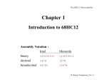
Determining the Appropriate GPIB Specifications
Command
Hierarchy
Standard Response
Format
Standard Program
Command Set
IE
EE
48
8.
2
Software/
Firmware
Common Commands
Syntax/Data Structures
IE
EE
48
8.
1
Hardware
Handshaking/Control
Mechanical/Electrical Standards
Figure 1. Structure of the GPIB Standards
IEEE 488.1
IEEE 488.1 specifies the handshaking, basic control, mechanical and electrical characteristics of the GPIB, but does
not specify the format of command strings or responses. All GPIB devices must comply with 488.1. Both the
NAT9914 and the TNT4882 handle all of the low-level 488.1 requirements. Because IEEE 488.1 has fewer
requirements, an IEEE 488.1 device is easier to implement than its 488.2 or the SCPI equivalent. The example device
discussed later in this application note is 488.1 compliant.
2
IEEE 488.2
All IEEE 488.2 devices are also 488.1 devices. In addition to 488.1 requirements, IEEE 488.2 specifies data formats
for commands and responses. The specification also standardizes error handling and status reporting, and it requires
all devices to include certain commands and optionally, several more commands. Designing a 488.2 device requires
more complicated firmware, but some end users find 488.2 devices easier to program. The NAT9914 and TNT4882
both can be used in 488.2 compliant devices. IEEE 488.2 will help a user if he has other 488.2 devices or if he is
comfortable with 488.2.
SCPI
SCPI adds to the 488.2 specifications by defining a single command set for all instruments. Many major instrument
manufacturers make SCPI-compliant devices. For a complete line of oscilloscopes or other instruments with large
command sets, SCPI provides a seamless, coherent interface while standardizing the command set.
Designing a Command Set
Command Set Completeness
Your command set should enable the user to control all functions of the device. Any functionality available through
the front panel should also be available remotely.
ASCII strings
Devices generally use 7-bit ASCII strings. ASCII strings are easy to read when debugging, platform independent, and
almost universally accepted among GPIB instruments. Capital letters are required by IEEE 488.2 and commonly used
in 488.1 instruments. Some devices also send 8-bit binary data in an IEEE specified format.
Commands and Queries
A command tells the device to perform a specific task. A command does not return information. A command might
tell a device to generate voltage or set a configuration option. A query requests information from the device. A query
might request the temperature or a voltage reading.
Command Set for the Example Device
This example device parses the incoming data for an ASCII string beginning with either a “VOLT?” query or “TARE”
command. With an expanded parsing routine, this device could become 488.2 or SCPI compliant.
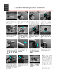
Designing the Hardware
Your hardware will connect a microcontroller to a NAT9914, and the NAT9914 to the GPIB connector through two
GPIB transceivers. In this example, the glue between the Motorola 68HC11 and the NAT9914 comes directly from
the 68HC11 manual and the wiring between the NAT9914 and the transceivers comes directly from the NAT9914 data
sheet. A set of DIP switches are included so the user can select a GPIB address; but otherwise the design is copied from
the M68HC11 manual and the NAT9914 data sheet. The Motorola 68HC11 microcontroller actually runs on an
evaluation board connected to the NAT9914 board with a 50-pin ribbon cable.
The program TEST.C checks the connection between the microcontroller and the NAT9914. TEST.C writes to each
address and alerts the user to errors in wiring.
Note the reverse order of the data lines entering the NAT9914. On the NAT9914, D0 is the most significant bit of the
data bus.
Schematic
The following diagram shows the schematic of the example board that plugs into the M68HC11 evaluation board:
3
Figure 2. Schematic of GPIB Device
4
The GAL decodes the address and expands the multiplexed address/data bus of the Motorola 68HC11 so the NAT9914
appears at the M68HC11 memory address 0x1080. The following abel code defines the behavior of the GAL:
Timing Charts
A GAL decodes the microcontroller bus and asserts a chip-enable signal when the microcontroller reads or writes to
the I/O location the NAT9914 occupies. This GAL also expands a multiplexed address/data bus for the NAT9914. In
the example device, the GAL has a propagation delay of 15 ns.
NAT9914 and M68HC11
CPU Read Timing Diagram
>225
E
>220
R/W
>88
M68HC11
30+
>298
HC11 Send Address
Receive Data
AS
CE
Address
Data
>153
>220
>250
DBIN
>63
NAT9914
Address
<20
<80
D(0-7)
Figure 2. GPIB Read Timing Diagram
NAT9914 and M68HC11
CPU Write Timing Diagram
>225
E
>220
>88
R/W
M68HC11
>33
<108
HC11 Data
AS
CE
NAT9914
WE
Address
Data
>135
>250
>88
Address
Figure 3. GPIB Write Timing Diagram
5
Parts List
Part Description
Manufacturer
Part Number
GPIB interface chip
National Instruments
NAT9914APD
Address decoder
Lattice
GAL20V8B-15LP
GPIB transceivers
National Semiconductor
DS75160AN, DS75162AN
GPIB connector
AMP
553121-1
2x30 Jumper block
Samtec
TSW-130-07-S-D
Microcontroller
Motorola
M68HC11EVM
Designing the Firmware
The firmware in the example device uses the following basic flowchart:
startup
output
output
a byte
initialize
device
foreground
processing
byte
out
interrupt
done
trigger
device
trigger
reset
get
DCAS
GPIB
interrupt
handler
byte
in
not
end of
message
input
a byte
clear
device
execute
command
last byte of
message
parse
command
input
Figure 4. GPIB FLow Chart
NAT9914 Initialization
Discussion of Code
The microcontroller might need to be configured first. The microcontroller “locks in” many configuration settings after
a preset number of cycles.
6
The software must initialize the variables and interrupt vectors before the NAT9914 leaves the ‘pon’ mode. In the ‘pon’
mode, the NAT9914 logically disconnects from the GPIB and will not be affected by any GPIB activity.
The NAT9914 will become logically connected when the microcontroller sends the ‘~pon’ message to the NAT9914.
From this time on, the device will handle incoming GPIB signals.
The initialization of the microcontroller will depend greatly on the microcontroller you use, so the rest of this section
discusses initialization concerns of the NAT9914.
Clock Frequency
The NAT9914 uses the clock to generate the required IEEE 488.1 T1 delay between reading bytes. A faster clock
makes the delays more precise, but a 20 MHz clock runs the chip only slightly faster than a 5 MHz clock. You should
set the clock speed in the ICR register to indicate the external clock speed.
GPIB Address
The microcontroller must send the GPIB address of the device to the NAT9914 during the start-up initialization. Often
the user sets the GPIB address with DIP switches. Only 0 through decimal 30 are valid addresses. If a user enters 31,
a device usually interprets this as address 30.
End of Message Condition
The four methods of terminating a message are:
•
The listener stops listening after a certain number of bytes
•
The talker asserts the GPIB EOI signal
•
The talker sends an EOS byte (usually a newline character, hex 0A)
•
The talker sends the EOS with the EOI signal asserted
On the NAT9914, the XEOS bit in the ACCRA register configures the NAT9914 to assert EOI whenever the device
sends the character in EOSR to another GPIB device. The REOS bit of the same register sets the END bit of ISR0 if
the GPIB device receives an EOS character.
T1 Delay
The T1 delay is the time allowed for GPIB lines to settle before DAV asserts and gives the listening GPIB device
enough setup time to ensure reliable data transfer. The length of the delay depends on the capabilities of the
transceivers, GPIB cable length, and the number of powered-on GPIB devices. The stdl, ~stdl, vstdl, and ~vstdl
commands to the AUXCR register and the USTD bit in the ACCRI register set the IEEE 488.1 T1 delay. The
NAT9914 automatically shortens the delay after the first byte it sends. Internally, the NAT9914 uses the clock setting
to count out the T1 delay, so set the ICR register to indicate the clock speed.
Holdoff Condition When Listening
A GPIB device can refuse to accept a data byte or command byte until the device has processed the previous incoming
bytes. The device asserts the NDAC or NRFD lines and finishes processing the data before the device unasserts NDAC
or NRFD to continue the handshake. Most GPIB devices hold off the trigger and device-clear commands with an
NDAC holdoff. Some devices also perform a holdoff on the last byte in a message string and parse the message before
releasing the holdoff.
7
Detecting GPIB Events
GPIB events affecting the device are recorded in the ISR0, ISR1, and ISR2 registers. They give access to the current
GPIB status of the device and latch GPIB information for the microcontroller. The act of reading one of the ISR
registers also clears it. Firmware can either poll the ISR registers or ignore them until the NAT9914 interrupts.
Polling
One way to detect GPIB activity is to periodically poll the ISR registers. Most bits will not affect your device, but the
device firmware usually polls the BO, BI, END, GET, and DCAS bits. This method is straightforward and does not
have the overhead of interrupt calls.
Interrupts
The NAT9914 can be configured to interrupt when any enabled ISR bit sets. Note that by reading ISR0 bits INT0 and
INT1, your program may be able to handle the interrupt slightly faster. To configure interrupts for use on the
NAT9914, set the IMR bits corresponding to the ISR conditions which will request an interrupt. Then set the global
interrupt bit in IMR2.
In the example device, interrupt vector points to route_nat9914_interrupts() and a Return from Interrupt
instruction (RTI) replaces the Return from Subroutine instruction (RTS) at the end of route_nat9914_interrupts.
route_nat9914_interrupts() now sorts out what caused the interrupt and processes it completely before returning microcontroller control back to the main program.
The NAT9914 INT* pin can be configured for active low or active high by setting or clearing the INV bit of the ACCRB
register. The INT* pin defaults to active low. The NAT9914 drives the INT* pin with an open collector gate, so wire
an external pullup resistor to it.
Parsing
The versatility of your device will specify the complexity of the parsing routine. This example device uses a simple
parsing algorithm. Both the buffer size and the parsing algorithm can easily be altered to accommodate more complex
command sets.
Reporting Device Status
The NAT9914 will return a status byte to the controller when the GPIB controller serial polls your device. The SPMR
register contains the status byte. The act of setting the RSV bit of the SPMR register asserts the SRQ line and requests
a serial poll. IEEE 488.2 defines the MAV bit, but leaves the lower nibble of the status byte device specific. The
NAT9914 handles serial polls without intervention by the microcontroller. This feature makes the status byte an ideal
place to keep status information and error messages.
Configure the SPMR through routines that strip away any writes to the RSV bit and replace writes to that particular bit
with calls to rsv2. In the example device, set_srq_bits() and clear_srq_bits() handle this function.
Some GPIB controllers automatically status poll devices and display the previous poll results instead of retrieving
newer status data. You may wish to disable auto serial polling when testing your device.
You can configure the NAT9914 with STBO IE in IMR2 to interrupt when the GPIB controller serial polls your device
and wait for the microcontroller to write a byte to the SPMR before the NAT9914 responds to the serial poll. For more
information on status reporting, refer to the NAT9914 Reference Manual.
8
Other Topics
Changing the End of Message Condition When Listening
The EOSR register stores the EOS byte. To change the EOS byte, write a new value to the EOSR register. Be careful
of changing the EOS character any time except start-up.
Sending Binary Data
When transferring binary data, use EOI, not EOS. To disable EOS, clear the XEOS and REOS bits in the ACCRA
register. To end a binary data transmission write the feoi command to the AUXCR register before writing the last byte
to the CDOR.
Compiling the Software
All assert statements are left in the code to ease debugging especially of a buffer overflow. You can enable the
assert() statements by replacing #define assert(a) {}; with #include <assert.h>.
To compile the software for a microcontroller:
1.
Test the glue between the microcontroller and the NAT9914 with Test.c
The short program Test.c was designed to test the connections on the microcontroller and ensure that it can communicate with the NAT9914. This series of tests read and write to each register and print an error message if any
of the tests fail. The tests must be run with no other devices attached to the GPIB port. Although this collection of
tests can run in any order, additional GPIB tests inserted before this collection of tests might set bits that a
soft-reset command to the NAT9914 would not clear.
To use Test.c on a microcontroller, compile Test.c and adjust the reset vector to point to the main body of the program. To observe the read/write operation of the microcontroller, connect a logic analyzer to all address/data lines.
2.
Add microcontroller initialization code to the function initialize_microcontroller().
With the exception of interrupt vectors, the M68HC11 initially powers up in the configuration that the NAT9914
and its board require. For interrupts, the external interrupt vector has to be set to point to
handle_nat9914_interrupts(). An enable external interrupt (CLI) instruction should just precede the clear software
reset (c_nswrst) command to the NAT9914.
3.
Update NAT9914 dependent code.
In initialize_NAT9914() remove the redundant lines:
outp(r7210_auxmr, c7210_sw9914);
and
outp(r_auxcr, c_ch_rst);
Adjust the clock speed by altering outp(r_accr, f_icr | f_1mhz) in initialize_NAT9914().
Reference Sources
IEEE Specifications
ANSI/IEEE Standard 488.1-1987, Digital Interface for Programmable Instrumentation (ANSI)
ANSI/IEEE 488.2-1992, IEEE Standard Codes, Formats, Protocols, and Common Commands for Use with IEEE Standard 488.1-1987, IEEE Standard Digital Interface for Programmable Instrumentation (ANSI)
9
SCPI Specifications
Fred Bode, Executive Director
SCPI Consortium
8380 Hercules Drive, Suite P3
La Mesa, CA 91942
Phone: (619) 697-8790
FAX: (619) 697-5955
GPIB Transceivers
National Semiconductor http://www.national.com
Texas Instruments (972) 644-5580 http://www.ti.com/sc/
GPIB Connectors
Emulation Technology, Inc. (409) 982-0660
L-Com, Inc. 1-800-343-1455 http://www.L-com.com
GPIB Hardware and Resources
National Instruments http://www.natinst.com
•
GPIB cables
•
GPIB controllers
•
NAT9914 Reference Manual
10
Appendix A – GPIB Tutorial
Introduction to the GPIB
This appendix discusses the history of the GPIB, GPIB hardware configurations, and serial polling.
History of the GPIB
Hewlett-Packard developed the original GPIB (and called it the HP-IB) in the late 1960s. Hewlett-Packard developed
its HB-IB to connect and control programmable instruments that Hewlett-Packard had manufactured. The introduction
of digital controllers and programmable test equipment created the need for a standard, high-speed interface that would
permit communication between instruments and controllers from various vendors. In 1975, the IEEE published
ANSI/IEEE Standard 488-1975, IEEE Standard Digital Interface for Programmable Instrumentation, which contained
the electrical, mechanical, and functional specifications of an interfacing system. The original IEEE 488-1975 was
revised in 1978 primarily for editorial clarification and addendum. This bus is now used worldwide and is known by
three names:
•
General Purpose Interface Bus (GPIB)
•
Hewlett-Packard Interface Bus (HP-IB)
•
IEEE 488 Bus
Because the original IEEE 488 document contained no guidelines for preferred syntax and format conventions, work
continued on the specification to enhance system compatibility and configurability among test systems. This work
resulted in a supplement standard—IEEE 488.2, Codes, Formats, Protocols, and Common Commands—that you use
with IEEE 488 (which was renamed IEEE 488.1).
IEEE 488.2 does not replace IEEE 488.1. Many devices still conform only to IEEE 488.1. IEEE 488.2 builds on IEEE
488.1 by defining a minimum set of device interface capabilities, a common set of data codes and formats, a device
message protocol, a generic set of commonly needed device commands, and a new status reporting model.
In 1990, a consortium of test and measurement companies developed the Standard Commands for Programmable
Instrumentation (SCPI) document. SCPI defines specific commands that each instrument class (which usually includes
instruments from various vendors) must obey. Thus, SCPI guarantees complete system compatibility and configurability among these instruments. You no longer need to learn a different command set for each instrument, and you can
easily replace an instrument from one vendor with an instrument from another.
The IEEE 488.1 Specification
The GPIB is a digital, 8-bit, parallel communications interface with maximum data transfer rates over 1 MB/s. The bus
supports one system controller—usually a computer—and up to 14 additional instruments. Because the GPIB is an
8-bit parallel interface with fast data transfer rates, it has gained popularity in other applications such as intercomputer
communication and peripheral control.
IEEE 488.2 and SCPI Specifications
Although IEEE 488.1 eliminated the need to find the right type of connector and determine which signal line was
connected to which pin, it did not solve other problems. More than 10 years after the release of IEEE 488.1, IEEE 488.2
and SCPI solved these problems.
Problems with IEEE 488.1 Compatible Devices
Users of IEEE 488.1 compatible devices encountered the following problems:
•
No common method for performing operations existed: In a system with two different meters, one meter could
require a command to take a reading while the other could take a reading without a command.
11
•
No common data format existed among communicating devices: Two communicating devices used two different
formats to represent the same number.
•
No common command set existed: Two devices performed identical functions, but used completely different
device-dependent data messages.
•
Status reporting was unique to each device: Each device reported its status information in a different format.
The IEEE 488.2 Solution
The IEEE 488.2 standard eliminates the IEEE 488.1 problems through the following solutions:
•
IEEE 488.2 contains a minimum set of required device interface capabilities.
•
IEEE 488.2 specifies a way of presenting data through data formats and codes.
•
IEEE 488.2 defines a specific protocol for sending device messages and the syntax for multiple commands in a
single string.
•
IEEE 488.2 contains a common command set.
•
IEEE 488.2 contains a standard status reporting model.
SCPI Specification
The SCPI specification expands the IEEE 488.2 common command set by defining a single, comprehensive command
set that is suitable for all instruments. For example, all SCPI-compatible voltmeters, regardless of manufacturer or
model, respond to the same command for reading AC voltage. Their response format is also the same.
SC
PI
SCPI embraces many of the commands and protocols that the hardware-independent portion of the IEEE 488.2 standard defines. Figure A-1 illustrates the structure of the GPIB standards.
Command
Hierarchy
Standard Response
Format
Standard Program
Command Set
IE
E
E
48
8.
2
Software/
Firmware
Common Commands
Syntax/Data Structures
IE
EE
48
8.
1
Hardware
Handshaking/Control
Mechanical/Electrical Standards
Figure A-1. Structure of the GPIB Standards
The combination of IEEE 488.2 and SCPI leads to greater productivity by featuring software command standards and
instant interchangeability. Rather than learning a different command set for each instrument, you can focus on solving
measurement problems.
12
Although you can mix SCPI and non-SCPI instruments in a system, your complete system must adhere to IEEE 488.2
for you to fully benefit from these standards.
See Appendix C, Standard Commands for Programmable Instruments (SCPI), for more information.
GPIB Hardware Configuration
A GPIB hardware setup consists of two or more GPIB devices (instruments and/or interface boards) that are connected
by a GPIB cable. The cable assembly consists of a shielded 24-conductor cable with a plug and a receptacle
(male/female) connector at each end. With this design, you can link devices in a linear configuration, a star
configuration, or a combination of these two configurations (see Figures A-2 and A-3).
Device A
Device B
Device C
13
Device A
Device D
Device B
Device C
Figure A-3. Star Configuration
GPIB Signals and Lines
The GPIB has 16 signal lines and 8 ground return or shield drain lines (see Figure A-4). All GPIB devices share the
same 24 bus lines. The 16 signal lines fall into three groups:
•
Eight data lines.
•
Five interface management lines.
•
Three handshake lines.
DIO1
DIO2
DIO3
DIO4
EOI
DAV
NRFD
NDAC
IFC
SRQ
ATN
SHIELD
1
2
3
4
5
6
7
8
9
10
11
12
13
14
15
16
17
18
19
20
21
22
23
24
DIO5
DIO6
DIO7
DIO8
REN
GND (TW PAIR W/DAV)
GND (TW PAIR W/NRFD)
GND (TW PAIR W/NDAC)
GND (TW PAIR W/IFC)
GND (TW PAIR W/SRQ)
GND (TW PAIR W/ATN)
SIGNAL GROUND
Figure A-4. GPIB Connector and Pin Assignments
14
Data Lines
The eight data lines, DIO1 through DIO8, carry the command and data messages on the GPIB. All commands and
most data use the 7-bit ASCII or ISO code set; thus, the eighth bit, DIO8, is not used or is used for parity.
Interface Management Lines
The following lines manage the flow of information across the GPIB:
•
Interface Clear (IFC)
•
Attention (ATN)
•
Remote Enable (REN)
•
End-or-Identify (EOI)
•
Service Request (SRQ)
Interface Clear (IFC)
Only the System Controller can control the IFC line. The System Controller uses IFC to take control of the bus
asynchronously. This action must initially be done to establish Controller status.
The IFC line is the master reset of the GPIB. When it is asserted, all devices return to a known quiescent state.
Interface Clear
(IFC)
– 300.0005
V
• Places all devices into quiescent state.
• Is asserted by System Controller.
Attention (ATN)
When the ATN line is asserted, all devices become Listeners and participate in the communication. ATN signifies that
a GPIB command message or data message is present on the data lines. When ATN is unasserted, information on the
bus is interpreted as a data message. When ATN is asserted, information on the bus is interpreted as a command
message.
Attention
(ATN)
– 300.0005
V
• Notifies devices of current data type.
• Is asserted by Controller-In-Charge.
ATN asserted
Controller
Command messages
All
Devices
ATN unasserted
Listener(s)
Talker
Data messages
15
Remote Enable (REN)
The System Controller uses the REN line to put devices into a remote state. Each device has its own remote/local state
capabilities. The IEEE 488 standard requires a device to go into a remote programming state whenever the REN line
is asserted and addressed to listen.
Remote Enable
(REN)
– 300.0005
V
• Enables devices for remote programming.
• Is asserted by System Controller.
End-or-Identify (EOI)
Some devices terminate their output data by using the EOI line. A Talker asserts EOI along with the last byte of data.
A Listener stops reading data when the EOI is asserted. More details of transfer termination are presented later. This
line is also used in parallel polling, which will be discussed later.
End Or Identify
(EOI)
– 300.0005
V
• Signals end of data.
• Signals the execution of a Parallel Poll.
• Is asserted by current Talker.
Service Request (SRQ)
A device asserts the SRQ line at any time in order to notify the CIC that it needs service. The SRQ line remains
asserted until the device is serial polled. The Controller must monitor SRQ, poll the device, and determine the type of
service the device needs.
Service Request
(SRQ)
– 300.0005
• Alerts Controller that service is needed.
• Is asserted by Non-Controller.
Handshake Lines
Three lines asynchronously control the transfer of message bytes among devices:
•
Not Ready For Data (NRFD)
•
Not Data Accepted (NDAC)
•
Data Valid (DAV)
16
V
The GPIB uses a three-wire interlocking handshake scheme. This handshake scheme guarantees that message bytes
on the data lines are sent and received without transmission error.
Not Ready For Data (NRFD)
The NRFD line indicates whether a device is ready to receive a data byte. When a Controller is sending commands,
all devices drive NRFD. When a Talker is sending data messages, only Listeners drive NRFD.
Not Data Accepted (NDAC)
The NDAC line indicates whether a device has accepted a data byte. When a Controller is sending commands, all
devices drive NRFD. When a Talker is sending data messages, only Listeners drive NRFD.
Note:
This handshake scheme limits the transfer rate on the GPIB to that of the slowest active
Listener. The transfer rate is limited because a Talker waits until all Listeners are ready
(that is, NRFD is false) before sending data and waits for all Listeners to accept data (that
is, NDAC is false) before transferring more data. Therefore, the slowest device dictates
the maximum GPIB transfer rate.
Data Valid (DAV)
The DAV line indicates whether signals on the data lines are stable (valid) and whether devices can safely accept the
signals. When the Controller sends commands, it controls DAV, and when the Talker sends data messages, it controls
DAV.
Figure A-5 illustrates the three-wire handshake process.
The GPIB uses negative logic with standard TTL voltage levels:
Logic Level
Voltage Level
0 – false (unasserted) > +2.0 V (high)
< +0.8 V (low)
1 – true (asserted)
Listener
Talker
{
{
Data
1
1
New Data is Valid
DAV
NRFD
Data Not Valid Anymore
6
3
Ready
2
Don't Send More Yet
4
5 Byte
Accepted
NDAC
Data
Transfer
Begins
2
Ready
Again
7
Data
Transfer
Ends
Figure A-5. Three-Wire Handshake Process
Three-Wire Handshake Process
GPIB devices use the three-wire handshake process to transfer information. The three-wire handshake process is
identical for command and data transfers. During command transfers, the Controller drives the DIO and DAV lines;
all devices drive the NRFD and NDAC lines. During data transfers, the Talker drives the DIO and DAV lines; all
Listeners drive the NRFD and NDAC lines.
Devices drive the NDAC and NRFD lines with open-collector drivers, so if any device drives NDAC (or NRFD) to a
low voltage level, the signal is logically asserted (true). If no device drives NDAC (or NRFD) to a low voltage level,
the signal floats to a high voltage level; thus, the signal is logically unasserted (false).
17
The following actions occur during the three-wire handshake process (refer to Figure A-5):
1.
The Talker (or Controller) places data on the DIO lines and waits at least T1 seconds.
2.
After the T1 delay, the Talker waits until the Listener unasserts NRFD. NRFD unasserted (not Not-Ready-For
Data) indicates that the Listener can receive the data byte.
3.
The Talker asserts DAV to indicate that new data is valid on the DIO lines.
4.
The Listener asserts NRFD to signal a Not Ready Status (Don't Send More Yet).
5.
When the Listener accepts the current byte (by placing it in some internal buffer or by otherwise processing it),
the Listener unasserts NDAC.
6.
The Talker unasserts DAV.
7.
The Listener asserts NDAC, then the Talker executes step 1 to begin transferring the next byte.
Physical and Electrical Specifications
To achieve the GPIB’s high data transfer rate, you must limit the physical distance between devices and the number
of devices on the bus. This limitation is necessary because the GPIB is a transmission line system. Any distance
beyond the maximum allowable cable length, as well as any excess GPIB device loads, can surpass interface circuit
drive capability.
The IEEE 488 standard dictates the following limits:
•
The total length of all cables is less than or equal to 2 m times the number of connected devices—up to a total
of 20 m.
•
No more than 15 devices are connected to each bus, with at least two-thirds of the devices powered on.
If you must exceed these limits, you can purchase bus extenders and expanders.
Controllers, Talkers, and Listeners
All buses operate under rules that ensure that data passes reliably and that instruments do not use the bus
simultaneously. To determine which device has active control of the bus, devices are categorized as Controllers,
Talkers, or Listeners. Whenever two devices communicate, one device will be a Talker and the other will be a Listener.
In addition, one device will always be a Controller.
Controllers
Most GPIB systems consist of one computer and a variety of instruments. In this type of system, the computer is
typically the System Controller. If multiple computers are connected, several devices can have Controller capability,
but only one Controller is active, or Controller-In-Charge (CIC), at a time. Active control can pass from the current
CIC to an idle Controller.
For each GPIB system, you must define a System Controller. You usually define the System Controller through jumper
settings on the GPIB interface board, a software configuration file, or both. Only one device on the bus, the System
Controller, can make itself the CIC.
The four primary responsibilities of a Controller are the following:
•
Defining the communication links.
•
Responding to devices requesting service.
•
Sending GPIB commands.
•
Passing/receiving control.
18
Talkers and Listeners
You can set most GPIB devices to be either Talkers or Listeners. However, some devices only talk or only listen. Each
device accepts its own command set and has its own method of terminating data strings. Talkers and Listeners have
the following properties:
•
•
Talkers
–
Are instructed by the Controller to talk.
–
Place data on the GPIB.
–
Permit only one device to talk at a time.
Listeners
–
Are instructed by the Controller to listen.
–
Read data that the Talker places on the GPIB.
–
Permit several devices to be Listeners simultaneously.
You can compare GPIB operation to a classroom. The instructor (Controller) controls the communication of data
between the students (devices). The instructor decides who talks and who listens. On the GPIB, a device cannot talk
or listen unless the Controller explicitly tells it to do so.
Figure A-6 shows a system setup example.
Controller
GPIB
Multimeter
– 300.0005
V
System Controller
Oscilloscope
Plotter
Figure A-6. System Setup Example
19
Data and Command Messages
In a classroom, when the instructor tells the students who is the Talker and who are the Listeners, his or her information
is a command—not the actual data information that the instructor will send. On the GPIB, this distinction is not so
intuitive. The bus management line, ATN, determines what type of message you are sending on the bus. If this line
is unasserted, the information on the bus is a data message; if this line is asserted, the information is a command
message from the Controller to all devices. The devices on the GPIB monitor the ATN line, determine the data type,
and treat the data appropriately.
GPIB Addressing Protocol
In a classroom, an instructor either speaks to the entire class or to a particular student. To speak to a student, the
instructor first addresses that student by name.
Addressing on the GPIB follows the same idea. Before any communication can take place on the bus, you must address
the Talker and Listener. Before any data passes between devices, the Controller determines who talks and who listens.
In the classroom, we address people by their names. However, on the GPIB, each device (including the Controller)
has a unique primary GPIB address in the range of 0 to 30 (decimal). The Controller places a command message specifying the addresses of the Talker and Listener devices on the bus.
The Controller sends a single byte (8 bits) of information for a Talker or Listener address command message. Address
command messages have the following format:
Bit
7
Data
6
5
TA LA
4
3
2
1
0
X
X
X
X
X
Bits 0 through 4 contain the binary GPIB primary address of the device in communication, and either bit 5—Listener
Address (LA)—or bit 6—Talker Address (TA)—will be set if the device is a Talker or a Listener. Bit 7 is never used
and is considered a don’t care bit. For simplicity, assume bit 7 is zero.
Consider an example in which a Controller at primary GPIB address 0 talks to a device at primary GPIB address 1. To
establish the communication link, the Controller must send its GPIB talk address and the device's listen address over
the GPIB. In this example, these addresses are as follows:
Bit Patterns Sent to Set Up Talker
Bit pattern:
Hexadecimal value:
01000000
010
00000
TA
ADR
0100
0000
4
0
20
Talker's GPIB Address is 0
Hex 40 = ASCII "@"
Refer to the Multiline Interface Command Messages table (in Appendix D) and find the hex 40 location. On the same
row under the Msg column, you see the message MTA0, which means My Talk Address 0. Hex 40 is the command
message for setting device 0 to be a Talker.
Bit Patterns Sent to Set Up Listener
Bit pattern:
00100001
001
LA
Hexadecimal value:
00001
ADR Listener's GPIB Address is 1
0010
0001
2
1
Hex 21 = ASCII "!"
Refer to the Multiline Interface Command Messages table and find the hex 21 location. On the same row under the
Msg column, you see the message MLA1, which means My Listen Address 1. Hex 21 is the command message for
setting device 1 to be a Listener.
Reading the Multiline Interface Command Messages Table
By using the Multiline Interface Command Messages table, you can understand how the GPIB circuitry interprets the
bit patterns to produce the proper message commands. The Multiline Interface Command Messages table is organized
into four groups of columns. The left or first group of columns (hex 00–1F) represents the primary GPIB addresses.
Moving to the right to the next group of columns (hex 20–3F), you will find the corresponding listen addresses (MLA).
The listen address of a device is formed by adding hex 20 to the GPIB primary address. Again, move right to the next
group of columns (hex 40–5F) for the corresponding talk addresses (MTA). You form the talk address of a device by
adding hex 40 to the GPIB primary address.
Secondary Addressing
A device can have a secondary address. A secondary address is in the range of 0 to 30 decimal (IE hex). To form a
secondary address command (bit pattern), add 96 decimal (60 hex) to the secondary address. You address a device
with a secondary address by sending the primary GPIB address, then the corresponding secondary address. With
secondary addressing, you can assign up to 961 talk and listen addresses. Most instruments do not use secondary
addressing. In the Multiline Interface Command Messages table, the group of columns on the right (hex 60–7F)
represents the secondary GPIB address commands.
Unaddressing Command Messages
The CIC uses two special command messages to clear the bus of Talkers and Listeners before assigning new Talkers
and Listeners. These command messages are Untalk and Unlisten. The Untalk (UNT) command (hex 5F (ASCII “_”))
unaddresses the current Talker. The Untalk command is merely a command for convenience, because addressing one
Talker automatically unaddresses all others. The Unlisten (UNL) command (hex 3F (ASCII “?”)) unaddresses all
current Listeners on the bus. You cannot unaddress only a single Listener if you have previously addressed several
Listeners. You must use the UNL command to guarantee that you address only desired Listeners.
21
Termination Methods
When devices send data over the GPIB, they use up to three different methods to signify the end of a data transfer.
These methods are EOS, EOI, and the count method.
Termination methods in GPIB are necessary only for data messages, not for command messages.
EOS Method
The EOS method uses an EOS character, which signifies the termination of data that devices send on the GPIB. This
EOS character can be any character. However, it is commonly a carriage return (hex 0D) or a line feed (hex 0A) that
the Talker places as the last character in a data string. The Listener reads individual data bytes from the Talker until
the Listener reads the EOS character. When the Listener reads the EOS character, it knows that there is no more data,
so it completes the read operation.
You must configure the Talker and Listener to use the EOS method before the communication takes place. Many
devices send specific EOS characters and look for specific characters from other devices, so it is important for you to
read the documentation for all devices to see which termination method the devices use.
To use the EOS method in a classroom setting, the instructor and students would use a certain word to finish all communication within the classroom. As with the GPIB, the instructor and students would define this method and the word
used before any communication took place. In the GPIB and in the classroom, the termination signal is sent by using
the normal data path (data lines in GPIB, or speech in the classroom).
EOI Method
The EOI method uses the GPIB EOI line, which is separate from the eight data lines on the GPIB. In the EOI method,
when the Talker sends the last byte of data in the transmission, it sets the EOI line high to specify that the byte is the
last byte to be sent. The Listener monitors the EOI line and recognizes when there is no more data. You must establish
ahead of time whether the Talker will use the EOI method, so you can correctly configure the Listener to watch the
EOI line.
Students could use the EOI method in the classroom: they would wave device cards in the air to signal when they have
finished speaking. This form of communication is separate from the method of sending data (speech), but the other
Listeners can monitor this communication while they receive data (hear the speech).
Count Method
The count method uses neither the EOI line nor the EOS character. In the count method, the device that receives
information specifies the number of bytes to read. Through this method, a listening device reads a specified amount
of data and prevents the talking device from sending more data. If you do not clear the remaining data from the bus,
you can recover it later.
Students can use the count method in the classroom. Students count the words of someone who is talking. The Listener
announces that he or she will listen to only a specified number of words. Beyond this number of words, the Listener
will not hear any further information from the Talker. If the Listener wants more information, he or she requests more
words from the Talker.
Combinations of Termination Methods
You can use any combination of the three termination methods to terminate communication on the GPIB. For
example, you can specify an EOS character and also use the EOI line method. In this case, when the end of the string
is reached, the device sending the data will send an EOS character and assert the EOI line. When you use more than
22
one method, the first termination method recognized causes the termination. In this example, the EOS character or
EOI line causes termination, depending on which method the device recognizes first.
In general, when you use more than one termination method at a time, all methods are logically ORed together for a
result. Therefore, if you use all three methods, the communication termination will take place if the device sees the
EOS character, the system asserts the EOI line, or the count value has been reached.
Serial Polling
Servicing SRQs
In the classroom, an instructor is in charge of the class and controls activity. The GPIB works in a similar fashion: the
Controller bus controls when tasks are performed. In the classroom, a student must have permission to speak, and on
the GPIB, no device can communicate unless it is addressed to talk on the bus. A device may, however, need to
communicate with the Controller before the Controller tells it to talk. In a classroom, students who have something to
say usually raise their hands. On the GPIB, any device can assert the SRQ line, which is separate from the data lines.
SRQ informs the Controller that a device needs attention. The next section discusses how the SRQ line is asserted and
how the device that asserts it is identified.
Serial Polling Devices
This section investigates how the GPIB handles the SRQ line. Remember the SRQ line purpose: signaling to the
Controller that a device needs attention. When SRQ is asserted, it is the responsibility of the Controller to determine
who requested service by checking all devices individually. Checking the devices individually is known as polling the
devices. The Controller can poll devices in two ways: in serial or in parallel. This appendix discusses serial polling.
Serial polling obtains specific information from a device. When you serial poll, the Controller sends a special command message—Serial Poll Enable (SPE)—to the device, directing it to return its serial poll status byte. The SPE
message sets the IEEE 488.1 serial poll mode in the device, so when the device is addressed to talk, it returns a single
8-bit status byte. This serial poll status byte is different for each type of instrument; except for one bit, you must refer
to the instrument user manual for information on the other bits. Bit 6 (hex 40) of any serial poll status byte indicates
whether a device requested service by asserting the SRQ line. The device uses the other seven bits of the status byte
to specify why it needs attention.
After the Controller reads the status byte, it sends another command message, Serial Poll Disable (SPD), to the device.
The SPD message terminates the serial poll mode, thus returning the device to its normal Talker/Listener state. Once
a device requesting service is serial polled, it usually unasserts the SRQ line.
23
When a serial poll is conducted, the following sequence of events occurs:
System Controller
GPIB Device
UNListen (UNL)
Controller Listen Address
Serial Poll Enable (SPE)
Generates Serial Poll Byte
Device Talk Address
Device Set as Talker
Read (IBRD) Serial Poll
Byte from Device
Serial Poll Byte Returned
Serial Poll Disable (SPD)
Turns off Serial Poll Mode
UNTalk (UNT) All Devices
Figure A-7. Events During a Serial Poll
Status Byte Model for IEEE 488.1
IEEE 488.1 defines only bit 6, the RQS bit, of the serial poll status byte (see the following table). If a device is
requesting service, it sets RQS. The meaning of the remaining bits is device dependent.
7
RQS
5
4
3
2
1
0
Status Byte Register
ESR and SRE Registers
The IEEE 488.2 standard defines a set of commands for controlling the GPIB. The standard also defines a new method
of working with the SRQ line on the GPIB. This section applies only to those GPIB devices that are IEEE 488.2
compatible. If a device is only IEEE 488.1 compatible, the previous section applies.
Status Byte Model for IEEE 488.2
IEEE 488.2 describes a scheme for status reporting. This scheme is required for all IEEE 488.2 instruments. With this
scheme, the Controller can obtain status information for every instrument in the system. This scheme builds on and
extends the IEEE 488.1 status byte shown in the above table. Three bits of this status byte are defined. The IEEE
488.2 standard defines the RQS bit like the IEEE 488.1 standard. IEEE 488.2 adds the Event Status Bit (ESB) and the
24
Message Available (MAV) bit. The manufacturer defines other bits. The RQS bit indicates the device has requested
service by asserting the SRQ line. The ESB indicates that one of the standard events defined in the Standard Event
Status Register has occurred. By setting the corresponding bits in the Standard Event Status Enable Register, you
define which standard events will set the ESB. The MAV bit indicates whether a message is available in the instrument
output queue. By setting the corresponding bits in the Service Request Enable Register, you can configure an
instrument to assert the SRQ line based on the bits of its status register.
Operation Complete
Request Control
Query Error
Device Dependent Error
Execution Error
Command Error
User Request
Power On
IEEE 488.2 defines a dual role for the RQS bit. This bit is also known as the Master Summary Status (MSS) bit. The
MSS bit indicates whether there is at least one reason for the instrument to request service. The status of this bit is
returned only in response to the status byte (STB) query; its status is not sent in response to a serial poll because this
bit is not part of the IEEE 488.1 status byte (see Figure A-8).
7 6 5 4 3 2 1 0
Logical OR
&
Standard
Event Status Register
*ESR?
&
&
&
&
Queue
Not-Empty
&
&
&
7 6 5 4 3 2 1 0
Standard
Event Status Enable
Register
*ESE <NRf >
*ESE?
read by Serial Poll
RQS
Service
Request
Generation
7 6
Output Queue
ESB MAV
3 2 1 0
MSS
Status Byte Register
read by *STB?
Logical OR
&
&
&
&
&
&
&
7
Service Request
Enable Register
*SRE <NRf >
*SRE?
5 4 3 2 1 0
Figure A-8. IEEE 488.2 Standard Status Structures
25
Parallel Polling
Parallel polling is another way to get information from a device that requests service. Parallel polling differs from
serial polling in two ways: all configured devices are polled simultaneously (that is, in parallel) and a Controller
initiates a parallel poll sequence (any device requests the initiation of a serial poll sequence).
Overview of Parallel Polls
A parallel poll is an exchange of messages between the Controller and other system devices. The Controller sends the
IDY message true to the other devices; each device responds to the IDY message by sending one PPR message (PPR1,
PPR2, PPR3, PPR4, PPR5, PPR6, PPR7, or PPR8) to the Controller. Each device usually sends a different PPR
message. (See the Physical Representation of the PPR Message section in this chapter.) Each device can send its PPR
message either true or false. See Figure A-9.
PPR1 = true
Device
IDY
Controller
PPR4 = False
Device
PPR6 = true
Device
Figure A-9. Example Exchange of Messages During a Parallel Poll
Determining the Value of the PPR Message
Each device examines its local ist message and its Sense bit (S) to determine whether it will send its PPR message true
or false. Table A-1 illustrates how the ist message and the Sense bit affect the value of the PPR message.
Table A-1. PPR Message Value
ist Message
Sense Bit (S)
PPR Message Sent
0 (False)
0
True
0 (False)
1
False
1 (True)
0
False
1 (True)
1
True
The ist message usually reflects a bit of status information about the device. For example, when the device has taken
a measurement, it can assert its local ist message. The Sense bit is part of the configuration of a device. Each device
has an independent Sense bit.
26
The meaning of the PPR message and the local ist message is device dependent.
Configuring a Device for Parallel Polls
To configure a device to respond to parallel polls, you must supply the device with two pieces of data:
•
The PPR message that the device should send to the Controller (PPR1, PPR2, . . , or PPR8)
•
The value of the Sense bit of the device.
You can configure devices locally or remotely. You locally configure (Parallel Poll function subset PP2) a device by
setting knobs or switches on the front panel of the device (or by physically manipulating the device in some other way).
You remotely configure (Parallel Poll function subset PP1) a device by sending messages across the GPIB from the
Controller to the device. If a device has not been configured to respond to parallel polls, it does not respond to parallel
polls.
Some devices support only local configuration and some support only remote configuration. Some devices do not support any parallel polls (Parallel Poll function subset PP0).
Determining the PPE Message
The PPE message contains the parallel poll configuration data for a device. Table A-2 shows how you determine the
value of DIO[7:1] for the PPE message. As with all commands, the DIO[8] is a don't care bit.
Table A-2. Determining the PPE Message
Sense Bit (S)
PPR Message
to Send
PPE Message
(hex)
0
0
0
0
PPR1
PPR2
PPR3
PPR4
60
61
62
63
0
0
0
0
PPR5
PPR6
PPR7
PPR8
64
65
66
67
1
1
1
1
PPR1
PPR2
PPR3
PPR4
68
69
6A
6B
1
1
1
1
PPR5
PPR6
PPR7
PPR8
6C
6D
6E
6F
Physical Representation of the PPR Message
To send a PPR message true, a device drives the corresponding GPIB DIO signal low with an open-collector driver.
For example, to send the PPR4 message true, a device drives the GPIB DIO4 signal low.
Because devices drive the DIO signals with open-collector drivers during parallel polls, more than one device can share
a PPR message. If a Controller detects a PPR message being sent true, the Controller knows that one or more of the
devices sharing the PPR message is sending the PPR message true.
27
Clearing and Triggering Devices
A Controller can clear devices in several ways. It can assert the IFC line to clear all devices, or it can send the Device
Clear (DCL) command message to clear all devices on the bus. To clear a single device, a Controller can address the
device to listen, then send the Selected Device Clear (SDC) command message.
After a device receives DCL or SDC, its clear state is device dependent. Generally, sending DCL or SDC is a less
extreme method of clearing a device than asserting IFC. Most devices support the DCL and SDC method; all devices
support the IFC method.
All devices in multidevice measurement systems must often be sampled as closely together as possible. You can trigger devices simultaneously by using the Group Execute Trigger (GET) command message. This command message
causes all devices that have triggering capability and that are currently addressed to initiate a preprogrammed action.
The action could be, for example, to take a measurement or begin a sweep.
28
Appendix B – Software Listings
Test.c
/*
tests.c 7/15/97
This file contains tests to determine whether the NAT9914 is connected
properly. It reads and writes to each register except the hidden registers in
ACCR. It is designed to be used unconnected to any other GPIB devices and
will interfere with them and they may confuse the tests.
*/
#define INT_TEST
#include "test.h"
#define trigger_logic_analyzer(a) *(unsigned char *)TRIGGER_ADDRESS = (a)
#define inp(io_address) *(unsigned char *)(io_address)
#define outp(io_address, o_data) *(unsigned char *)(io_address) = (o_data);
u_8 interrupt_pending;
/*
* ---------------------------------------------------------------------------* --- ****************** TEST TABLES AND SPECIAL TEST ROUTINES *******************
* Updated May 28, 1997, fully functional
* --------------------------------------------------------------------------* ---*/
/************************
Simple tests (1..9)
**************************/
/* Test 1 - check ADSR and ISR0 by programming to talk with 'ton' */
struct ck
t1[] = {
{WT, tauxmr,0x15},
/* switch to 9914 mode */
{WT, auxcr, 0x1c},
/* reset chip */
{WT, auxcr, 0x80},
/* reset chip */
{WT, auxcr, 0x00},
/* reset chip */
{WT, auxcr, 0x1e},
/* page in to imr2 */
{WT, imr2, 0x00},
/* clear GLINT bit and imr2*/
{WT, imr1, 0x00},
/* clear imr1 */
{WT, imr0, 0x00},
/* clear imr0 */
{WT, auxcr, 0x8a},
/* 'ton' */
{RD, isr0, 0x10},
/* BO bit set - no interrupts */
{RD, isr1, 0x00},
{RD, adsr, 0x02},
/* 9914A is TADS */
{WT, auxcr, 0x0a},
/* clear 'ton' */
{RD, adsr, 0x00},
/* TADS cleared */
{0}};
tst1()
{
return testit(t1);
29
}
/* Test 2 - check ISR2 with CDOR */
struct ck
t2[] = {
{WT, tauxmr,0x15},
/* switch to 9914 mode */
{WT, auxcr, 0x1c},
/* reset chip */
{WT, auxcr, 0x80},
/* reset chip */
{WT, auxcr, 0x00},
/* reset chip */
{WT, auxcr, 0x1e},
/* page in to imr2 */
{WT, imr2, 0x00},
/* clear GLINT bit */
{WT, imr1, 0x00},
/* clear imr1 */
{WT, imr0, 0x00},
/* clear imr0 */
{RD, isr2, 0x00},
/* all clear */
{WT, cdor, 0xaa},
/* set nba bit in isr2 by writing to cdor */
{RD, isr2, 0x80},
/* make sure nba bit is set*/
{0}};
tst2()
{
return testit(t2);
}
/* Test 3 - check BCR by reading from a write to BSR */
struct ck
t3[] = {
{WT, tauxmr,0x15},
/* switch to 9914 mode */
{WT, auxcr, 0x1c},
/* reset chip */
{WT, auxcr, 0x80},
/* reset chip */
{WT, auxcr, 0x00},
/* reset chip */
{WT, auxcr, 0x1e},
/* page in to imr2 */
{WT, imr2, 0x00},
/* clear GLINT bit */
{WT, imr1, 0x00},
/* clear imr1 */
{WT, imr0, 0x00},
/* clear imr0 */
{WT, auxcr, 0x1f},
/* page in to bcr register */
{WT, bcr,
0x40},
/* set DAV internal to the NAT9914 */
{RD, bsr,
0x40},
/* read internal DAV signal */
{0}};
tst3()
{
return testit(t3);
}
/* test 4 check ISR1 with ERR flag */
struct ck
t4[] = {
{WT, tauxmr,0x15},
/* switch to 9914 mode */
{WT, auxcr, 0x1c},
/* reset chip */
{WT, auxcr, 0x80},
/* reset chip */
{WT, auxcr, 0x00},
/* reset chip */
{WT, auxcr, 0x1e},
/* page in to imr2 */
{WT, imr2, 0x00},
/* clear GLINT bit */
{WT, imr1, 0x00},
/* clear imr1 */
{WT, imr0, 0x00},
/* clear imr0 */
30
{WT, auxcr, 0x8a},
{WT, cdor, 0x55},
{RD, isr1, 0x40},
{0}};
/* set to ton*/
/* try to output some data*/
/* ERRor flag set because no one answered*/
tst4()
{
return testit(t4);
}
/* test 5 check ADR by enabling dat */
struct ck
t5[] = {
{WT, tauxmr,0x15},
/* switch to 9914 mode */
{WT, auxcr, 0x1c},
/* reset chip */
{WT, auxcr, 0x80},
/* reset chip */
{WT, auxcr, 0x00},
/* reset chip */
{WT, auxcr, 0x1e},
/* page in to imr2 */
{WT, imr2, 0x00},
/* clear GLINT bit */
{WT, imr1, 0x00},
/* clear imr1 */
{WT, imr0, 0x00},
/* clear imr0 */
{WT, auxcr, 0x8a},
/* set to ton*/
{WT, cdor, 0x55},
/* try to output some data*/
{RD, cptr, 0x55},
/* make sure it is talking correctly*/
{WT, adr,
0x20},
/* disable talk with dat */
{RD, cptr, 0x00},
/* no talking */
{WT, adr,
0x00},
/* enable talking for other tests */
{0}};
tst5()
{
return testit(t5);
}
/* test 6 check SPMR/SPSR by writing and checking */
struct ck
t6[] = {
{WT, tauxmr,0x15},
/* switch to 9914 mode */
{WT, auxcr, 0x1c},
/* reset chip */
{WT, auxcr, 0x80},
/* reset chip */
{WT, auxcr, 0x00},
/* reset chip */
{WT, auxcr, 0x1e},
/* page in to imr2 */
{WT, imr2, 0x00},
/* clear GLINT bit */
{WT, imr1, 0x00},
/* clear imr1 */
{WT, imr0, 0x00},
/* clear imr0 */
{WT, auxcr, 0x1f},
/* page in to use spsr */
{WT, spmr, 0xaa},
/* set spmr */
{RD, spsr, 0xaa},
/* check spsr */
{0}};
tst6()
{
return testit(t6);
}
31
/* test 7 check CDOR and
struct ck
t7[]
{WT, tauxmr,0x15},
/*
{WT, auxcr, 0x1c},
/*
{WT, auxcr, 0x80},
/*
{WT, auxcr, 0x00},
/*
{WT, auxcr, 0x1e},
/*
{WT, imr2, 0x00},
/*
{WT, imr1, 0x00},
/*
{WT, imr0, 0x00},
/*
{WT, auxcr, 0x8a},
/*
{WT, cdor, 0x55},
/*
{RD, cptr, 0x55},
/*
{0}};
CPTR by talking and
= {
switch to 9914 mode
reset chip */
reset chip */
reset chip */
page in to imr2 */
clear GLINT bit */
clear imr1 */
clear imr0 */
address to talk */
assert data to cdor
hear it on the line
hearing it back */
*/
*/
*/
tst7()
{
return testit(t7);
}
/* test 8 - check DIR by listening for silence */
struct ck
t8[] = {
{WT, tauxmr,0x15},
/* switch to 9914 mode */
{WT, auxcr, 0x1c},
/* reset chip */
{WT, auxcr, 0x80},
/* reset chip */
{WT, auxcr, 0x00},
/* reset chip */
{WT, auxcr, 0x1e},
/* page in to imr2 */
{WT, imr2, 0x00},
/* clear GLINT bit */
{WT, imr1, 0x00},
/* clear imr1 */
{WT, imr0, 0x00},
/* clear imr0 */
{WT, auxcr, 0x89},
/* lon */
{WT, auxcr, 0x1f},
/* page to BCR */
{WT, bcr,
0x40},
/* assert DAV and handshake */
{RD, dir,
0x00},
/* check DIR */
{0}};
tst8()
{
return testit(t8);
}
/* test 9 - check PPR by initiating a parallel poll */
struct ck
t9[] = {
{WT, tauxmr,0x15},
/* switch to 9914 mode */
{WT, auxcr, 0x1c},
/* reset chip */
{WT, auxcr, 0x80},
/* reset chip */
{WT, auxcr, 0x00},
/* reset chip */
{WT, auxcr, 0x1e},
/* page in to imr2 */
{WT, imr2, 0x00},
/* clear GLINT bit */
{WT, imr1, 0x00},
/* clear imr1 */
{WT, imr0, 0x00},
/* clear imr0 */
{WT, ppr,
0xaa},
/* fill the PPR with data */
{WT, auxcr, 0x1f},
/* page to BCR */
32
{WT, bcr,
{RD, cptr,
{0}};
0x88},
0xaa},
/* set EOI and ATN high */
tst9()
{
return testit(t9);
}
/******************
IMR tests
***********************
disable interrupts with GLINT and check them by reading
INT0 and INT1. IMR2 is implicitly tested since the GLINT
bit is used in both tests.
************************************************************/
/* test 10 - check IMR0 */
struct ck
t10[] = {
{WT, tauxmr,0x15},
/* switch to 9914 mode */
{WT, auxcr, 0x1c},
/* reset chip */
{WT, auxcr, 0x80},
/* reset chip */
{WT, auxcr, 0x00},
/* reset chip */
{WT, auxcr, 0x1e},
/* page in to IMR2 */
{WT, imr2, 0x00},
/* turn off GLINT */
{WT, imr1, 0x00},
/* clear imr1 */
{WT, imr0, 0x00},
/* clear imr0 */
{WT, imr0, 0x10},
/* enable BO IE */
{WT, auxcr, 0x8a},
/* ton */
{RD, isr0, 0x90},
/* INT0 and BO */
{WT, imr0, 0x00},
/* clear flags for other tests */
{0}};
tst10()
{
return testit(t10);
}
/* test 11 - check IMR1 */
struct ck
t11[] = {
{WT, tauxmr,0x15},
/* switch to 9914 mode */
{WT, auxcr, 0x1c},
/* reset chip */
{WT, auxcr, 0x80},
/* reset chip */
{WT, auxcr, 0x00},
/* reset chip */
{WT, auxcr, 0x1e},
/* page in to IMR2 */
{WT, imr2, 0x00},
/* turn off GLINT */
{WT, imr1, 0x00},
/* clear imr1 */
{WT, imr0, 0x00},
/* clear imr0 */
{WT, imr1, 0x40},
/* enable ERR IE */
{WT, auxcr, 0x8a},
/* ton */
{WT, cdor, 0xaa},
/* fill CDOR */
{RD, isr0, 0x40},
/* check for interrupt */
{WT, imr1, 0x00},
/* clear flags for other tests */
{0}};
tst11()
33
{
return testit(t11);
}
#ifdef INT_TEST
/* test 12 - Interrupt Test */
struct ck
t12[] = {
{WT, tauxmr,0x15},
/* switch to 9914 mode */
{WT, auxcr, 0x1c},
/* reset chip */
{WT, auxcr, 0x80},
/* reset chip */
{WT, auxcr, 0x00},
/* reset chip */
{WT, auxcr, 0x1e},
/* page in to IMR2 */
{WT, imr2, 0x80},
/* turn on GLINT */
{WT, imr1, 0x00},
/* clear imr1 */
{WT, imr0, 0x00},
/* clear imr0 */
{WT, imr0, 0x10},
/* enable BO IE */
{WT, auxcr, 0x8a},
/* ton */
{RD, isr0, 0x90},
/* INT0 and BO */
{0}};
tst12()
{
u_8 i;
/* set up conditions for an interrupt */
interrupt_pending = 1;
asm("cli");
outp(tauxmr,0x15);
outp(auxcr, 0x1c);
outp(auxcr, 0x80);
outp(auxcr, 0x00);
outp(auxcr, 0x1e);
outp(imr0, 0x10);
outp(auxcr, 0x8a);
/*
/*
/*
/*
/*
/*
/*
switch to 9914 mode */
reset chip */
reset chip */
reset chip */
page in to IMR2 */
enable BO IE */
ton */
/* wait for the interrupt */
asm( "nop\n"
"nop\n"
"nop\n"
"nop\n");
trigger_logic_analyzer(0x20);
/* check for the interrupt */
if (interrupt_pending==0){
/* interrupt worked */
trigger_logic_analyzer(0x21);
}
else {
/* interrupt failed */
trigger_logic_analyzer(0x22);
}
34
/* reset NAT9914 to not interfere with subsequent tests */
outp(imr0, 0x00);
}
/* clear a flag to indicate that the interrupt handler was called successfully
*/
#pragma interrupt_handler int_handler
void int_handler(){
/* signal rest of program that the interrupt has been handled
*/
interrupt_pending = 0;
/* handle the interrupt by writing out some output, in this case 0xaa
*/
outp( cdor, 0xaa);
}
#endif
/* ------------------------------------------------------------------Main program
*/
/* Set the starting address of the program
*/
#pragma abs_address:0xF000
void main() {
loop_start:
trigger_logic_analyzer(0x01);
tst1();
tst2();
tst3();
tst4();
tst5();
tst6();
tst7();
tst8();
tst9();
tst10();
tst11();
tst12();
trigger_logic_analyzer(0x10);
goto loop_start;
}
u_8 testit(struct ck *list_of_tests) {
u_8 read_value=0;
u_8 i=0;
u_8 errorflag=0;
while((list_of_tests+i)->action) {
35
if((list_of_tests+i)->action == RD) {
read_value = inp((list_of_tests+i)->chip_register);
if (read_value != (list_of_tests+i)->chip_data) {
errorflag = 1;
}
}
if ((list_of_tests+i)->action == WT) {
outp((list_of_tests+i)->chip_register,
(list_of_tests+i)->chip_data);
}
trigger_logic_analyzer(0x02);
i++;
}/*end the loop*/
/*print a message saying it passed the test.*/
if (!errorflag) trigger_logic_analyzer(0x04);
else trigger_logic_analyzer(0x08);
return errorflag;
}
36
Test.h
/*
tests.h
*/
#define BASE_ADDRESS 0x1080
#define TRIGGER_ADDRESS 0x1111
#define RD 1
#define WT 2
#define CLR 0
typedef unsigned char u_8;
struct ck {
u_8 action;
unsigned chip_register;
u_8 chip_data;
};
u_8 testit(struct ck *list_of_tests);
/* define i/o addresses of the registers on the nat9914 */
#define
#define
#define
#define
#define
#define
#define
#define
#define
#define
#define
#define
#define
#define
#define
#define
#define
#define
#define
#define
isr0 BASE_ADDRESS
imr0 BASE_ADDRESS
isr1 BASE_ADDRESS+1
imr1 BASE_ADDRESS+1
adsr BASE_ADDRESS+2
imr2 BASE_ADDRESS+2
eosr BASE_ADDRESS+2
bcr BASE_ADDRESS+2
accr BASE_ADDRESS+2
bsr BASE_ADDRESS+3
auxcr BASE_ADDRESS+3
isr2 BASE_ADDRESS+4
adr BASE_ADDRESS+4
spmr BASE_ADDRESS+5
spsr BASE_ADDRESS+5
cptr BASE_ADDRESS+6
ppr BASE_ADDRESS+6
dir BASE_ADDRESS+7
cdor BASE_ADDRESS+7
tauxmr BASE_ADDRESS+5
/* isr0
#define
#define
#define
#define
bits*/
b_int0
b_int1
b_bi
b_bo
0x80
0x40
0x20
0x10
37
#define
#define
#define
#define
b_end
b_spas
b_rlc
b_mac
0x08
0x04
0x02
0x01
/* imr0
#define
#define
#define
#define
#define
#define
#define
#define
bits*/
b_dma0
b_dma1
b_bi_ie
b_bo_ie
b_end_ie
b_spas_ie
b_rlc_ie
b_mac_ie
0x80
0x40
0x20
0x10
0x08
0x04
0x02
0x01
/* isr1
#define
#define
#define
#define
#define
#define
#define
#define
bits*/
b_get
b_err
b_unc
b_apt
b_dcas
b_ma
b_srq
b_ifc
0x80
0x40
0x20
0x10
0x08
0x04
0x02
0x01
/* imr1
#define
#define
#define
#define
#define
#define
#define
#define
bits*/
b_get_ie
b_err_ie
b_unc_ie
b_apt_ie
b_dcas_ie
b_ma_ie
b_srq_ie
b_ifc_ie
0x80
0x40
0x20
0x10
0x08
0x04
0x02
0x01
/* adsr
#define
#define
#define
#define
#define
#define
#define
#define
bits */
b_rem
b_llo
b_atn
b_lpas
b_tpas
b_la
b_ta
b_ulpa
0x80
0x40
0x20
0x10
0x08
0x04
0x02
0x01
/* imr2
#define
#define
#define
#define
#define
#define
bits */
b_glint
b_stbo_ie
b_nlen
b_lloc_ie
b_atni_ie
b_cic_ie
0x80
0x40
0x20
0x08
0x04
0x01
/* bcr bits */
38
#define
#define
#define
#define
#define
#define
#define
#define
b_bcr_atn
b_bcr_dav
b_bcr_ndac
b_bcr_nrfd
b_bcr_eoi
b_bcr_srq
b_bcr_ifc
b_bcr_ren
0x80
0x40
0x20
0x10
0x08
0x04
0x02
0x01
/* accr
#define
#define
#define
#define
#define
#define
bits (shadow registers)*/
b_icr
0x20
b_accra
0x80
b_accrb
0xa0
b_accre
0xc0
b_accrf
0xd0
b_accri
0xe0
/* bsr bits are identical to bcr*/
/* isr2
#define
#define
#define
#define
#define
#define
#define
bits */
b_nba
b_stbo
b_nl
b_eos
b_lloc
b_atni
b_cic
/* adr bits */
#define b_edpa
#define b_dal
#define b_dat
0x80
0x40
0x20
0x10
0x08
0x04
0x01
0x80
0x40
0x20
/* spmr/spsr bits */
#define b_rsv
0x40
#define b_mav
0x10
/* accra bits */
#define b_bin
#define b_xeos
#define b_reos
0x10
0x08
0x04
/* accrb bits */
#define b_iss
#define b_inv
#define b_lwc
#define b_speoi
#define b_atct
0x10
0x08
0x04
0x02
0x01
/* accre bits */
#define b_dhadt
#define b_dhadc
0x08
0x04
39
/* accrf bits */
#define b_dhata
#define b_dhala
#define b_dhuntl
#define b_dhall
0x08
0x04
0x02
0x01
/* accri bits */
#define b_ustd
#define b_pp1
#define b_dmae
0x08
0x04
0x01
/* turbo 488 cmdr bits */
#define bt488_sc_en 0x01
#define bt488_sc
0x02
/* auxcr commands */
#define c_nswrst 0x00
#define c_swrst
0x80
#define c_nonvalid 0x01
#define c_valid
0x81
#define c_rhdf
0x02
#define c_nhdfa
0x03
#define c_hdfa
0x83
#define c_nhdfe
0x04
#define c_hdfe
0x84
#define c_nbaf
0x05
#define c_nfget
0x06
#define c_fget
0x86
#define c_nrtl
0x07
#define c_rtl
0x87
#define c_feoi
0x08
#define c_nlon
0x09
#define c_lon
0x89
#define c_nton
0x0a
#define c_ton
0x8a
#define c_gts
0x0b
#define c_tca
0x0c
#define c_tcs
0x0d
#define c_nrpp
0x0e
#define c_rpp
0x8e
#define c_nsic
0x0f
#define c_sic
0x8f
#define c_nsre
0x10
#define c_sre
0x90
#define c_rqc
0x11
#define c_rlc
0x12
#define c_ndai
0x13
#define c_dai
0x93
#define c_pts
0x14
#define c_nstdl
0x15
#define c_stdl
0x95
#define c_nshdw
0x16
#define c_shdw
0x96
40
#define
#define
#define
#define
#define
#define
#define
#define
#define
#define
#define
#define
#define
#define
#define
#define
c_nvstdl 0x17
c_vstdl
0x97
c_nrsv2
0x18
c_rsv2
0x98
c_sw7210 0x99
c_reqf
0x1a
c_reqt
0x9a
c_ch_rst 0x1c
c_nist
0x1d
c_ist
0x9d
c_piimr2 0x1e
c_pibcr
0x1f
c_clrpi
0x9c
c_pieosr 0x9e
c_piaccr 0x9f
c7210_sw9914 0x15
41
Test.s
.area data
.globl _t1
_t1:
.byte 2
.word 0x1085
.byte 21
.byte 2
.word 0x1083
.byte 28
.byte 2
.word 0x1083
.byte 128
.byte 2
.word 0x1083
.byte 0
.byte 2
.word 0x1083
.byte 30
.byte 2
.word 0x1082
.byte 0
.byte 2
.word 0x1081
.byte 0
.byte 2
.word 0x1080
.byte 0
.byte 2
.word 0x1083
.byte 138
.byte 1
.word 0x1080
.byte 16
.byte 1
.word 0x1081
.byte 0
.byte 1
.word 0x1082
.byte 2
.byte 2
.word 0x1083
.byte 10
.byte 1
.word 0x1082
.byte 0
.byte 0
.blkb 3
.area text
.globl _tst1
_tst1:
TEST.49::
; /*
; tests.c 7/15/97
42
;
;
;
;
;
;
;
;
;
;
;
;
;
;
;
;
;
;
;
;
;
;
;
;
;
;
;
;
;
;
;
;
;
;
;
;
;
;
;
;
;
;
;
;
;
;
;
This file contains tests to determine whether the NAT9914 is connected
properly. It reads and writes to each register except the hidden registers in
ACCR. It is designed to be used unconnected to any other GPIB devices and
will interfere with them and they may confuse the tests.
*/
#define INT_TEST
#include "test.h"
#define trigger_logic_analyzer(a) *(unsigned char *)TRIGGER_ADDRESS = (a)
#define inp(io_address) *(unsigned char *)(io_address)
#define outp(io_address, o_data) *(unsigned char *)(io_address) = (o_data);
u_8 interrupt_pending;
/*
* ---------------------------------------------------------------------------* --- ****************** TEST TABLES AND SPECIAL TEST ROUTINES *******************
* Updated May 28, 1997, fully functional
* --------------------------------------------------------------------------* ---*/
/************************
Simple tests (1..9)
**************************/
/* Test 1 - check ADSR and ISR0 by programming to talk with 'ton' */
struct ck
t1[] = {
{WT, tauxmr,0x15},
{WT, auxcr, 0x1c},
/* reset chip */
{WT, auxcr, 0x80},
/* reset chip */
{WT, auxcr, 0x00},
/* reset chip */
{WT, auxcr, 0x1e},
/* page in to imr2 */
{WT, imr2, 0x00},
/* clear GLINT bit and imr2*/
{WT, imr1, 0x00},
/* clear imr1 */
{WT, imr0, 0x00},
/* clear imr0 */
{WT, auxcr, 0x8a},
/* 'ton' */
{RD, isr0, 0x10},
/* BO bit set - no interrupts */
{RD, isr1, 0x00},
{RD, adsr, 0x02},
/* 9914A is TADS */
{WT, auxcr, 0x0a},
/* clear 'ton' */
{RD, adsr, 0x00},
/* TADS cleared */
{0}};
tst1()
{
return testit(t1);
ldd #_t1
jsr _testit
clra
tsx
rts
L1:
.area data
43
.globl _t2
_t2:
.byte 2
.word 0x1085
.byte 21
.byte 2
.word 0x1083
.byte 28
.byte 2
.word 0x1083
.byte 128
.byte 2
.word 0x1083
.byte 0
.byte 2
.word 0x1083
.byte 30
.byte 2
.word 0x1082
.byte 0
.byte 2
.word 0x1081
.byte 0
.byte 2
.word 0x1080
.byte 0
.byte 1
.word 0x1084
.byte 0
.byte 2
.word 0x1087
.byte 170
.byte 1
.word 0x1084
.byte 128
.byte 0
.blkb 3
.area text
.globl _tst2
_tst2:
TEST.70::
; }
;
;
; /* Test 2 - check ISR2 with CDOR */
; struct ck
t2[] = {
;
{WT, tauxmr,0x15},
;
{WT, auxcr, 0x1c},
/* reset chip */
;
{WT, auxcr, 0x80},
/* reset chip */
;
{WT, auxcr, 0x00},
/* reset chip */
;
{WT, auxcr, 0x1e},
/* page in to imr2 */
;
{WT, imr2, 0x00},
/* clear GLINT bit */
;
{WT, imr1, 0x00},
/* clear imr1 */
;
{WT, imr0, 0x00},
/* clear imr0 */
;
{RD, isr2, 0x00},
/* all clear */
44
;
{WT, cdor, 0xaa},
;
{RD, isr2, 0x80},
; {0}};
;
; tst2()
; {
;
return testit(t2);
ldd #_t2
jsr _testit
clra
tsx
rts
L2:
.area data
.globl _t3
_t3:
.byte 2
.word 0x1085
.byte 21
.byte 2
.word 0x1083
.byte 28
.byte 2
.word 0x1083
.byte 128
.byte 2
.word 0x1083
.byte 0
.byte 2
.word 0x1083
.byte 30
.byte 2
.word 0x1082
.byte 0
.byte 2
.word 0x1081
.byte 0
.byte 2
.word 0x1080
.byte 0
.byte 2
.word 0x1083
.byte 31
.byte 2
.word 0x1082
.byte 64
.byte 1
.word 0x1083
.byte 64
.byte 0
.blkb 3
.area text
.globl _tst3
_tst3:
/* set nba bit in isr2 by writing to cdor */
/* make sure nba bit is set*/
45
TEST.90::
; }
;
; /* Test 3 - check BCR by reading from a write to BSR */
; struct ck
t3[] = {
;
{WT, tauxmr,0x15},
;
{WT, auxcr, 0x1c},
/* reset chip */
;
{WT, auxcr, 0x80},
/* reset chip */
;
{WT, auxcr, 0x00},
/* reset chip */
;
{WT, auxcr, 0x1e},
/* page in to imr2 */
;
{WT, imr2, 0x00},
/* clear GLINT bit */
;
{WT, imr1, 0x00},
/* clear imr1 */
;
{WT, imr0, 0x00},
/* clear imr0 */
;
{WT, auxcr, 0x1f},
/* page in to bcr register */
;
{WT, bcr,
0x40},
/* set DAV internal to the NAT9914 */
;
{RD, bsr,
0x40},
/* read internal DAV signal */
; {0}};
;
; tst3()
; {
;
return testit(t3);
ldd #_t3
jsr _testit
clra
tsx
rts
L3:
.area data
.globl _t4
_t4:
.byte 2
.word 0x1085
.byte 21
.byte 2
.word 0x1083
.byte 28
.byte 2
.word 0x1083
.byte 128
.byte 2
.word 0x1083
.byte 0
.byte 2
.word 0x1083
.byte 30
.byte 2
.word 0x1082
.byte 0
.byte 2
.word 0x1081
.byte 0
.byte 2
.word 0x1080
.byte 0
.byte 2
46
.word 0x1083
.byte 138
.byte 2
.word 0x1087
.byte 85
.byte 1
.word 0x1081
.byte 64
.byte 0
.blkb 3
.area text
.globl _tst4
_tst4:
TEST.111::
; }
;
;
; /* test 4 check ISR1 with ERR flag */
; struct ck
t4[] = {
;
{WT, tauxmr,0x15},
/* switch to 9914 mode */
;
{WT, auxcr, 0x1c},
/* reset chip */
;
{WT, auxcr, 0x80},
/* reset chip */
;
{WT, auxcr, 0x00},
/* reset chip */
;
{WT, auxcr, 0x1e},
/* page in to imr2 */
;
{WT, imr2, 0x00},
/* clear GLINT bit */
;
{WT, imr1, 0x00},
/* clear imr1 */
;
{WT, imr0, 0x00},
/* clear imr0 */
;
{WT, auxcr, 0x8a}, /* set to ton*/
;
{WT, cdor, 0x55}, /* try to output some data*/
;
{RD, isr1, 0x40}, /* ERRor flag set because no one answered*/
; {0}};
;
; tst4()
; {
;
return testit(t4);
ldd #_t4
jsr _testit
clra
tsx
rts
L4:
.area data
.globl _t5
_t5:
.byte 2
.word 0x1085
.byte 21
.byte 2
.word 0x1083
.byte 28
.byte 2
.word 0x1083
.byte 128
.byte 2
.word 0x1083
47
.byte 0
.byte 2
.word 0x1083
.byte 30
.byte 2
.word 0x1082
.byte 0
.byte 2
.word 0x1081
.byte 0
.byte 2
.word 0x1080
.byte 0
.byte 2
.word 0x1083
.byte 138
.byte 2
.word 0x1087
.byte 85
.byte 1
.word 0x1086
.byte 85
.byte 2
.word 0x1084
.byte 32
.byte 1
.word 0x1086
.byte 0
.byte 2
.word 0x1084
.byte 0
.byte 0
.blkb 3
.area text
.globl _tst5
_tst5:
TEST.135::
; }
;
;
; /* test 5 check ADR by enabling dat */
; struct ck
t5[] = {
;
{WT, tauxmr,0x15},
/* switch to 9914 mode */
;
{WT, auxcr, 0x1c},
/* reset chip */
;
{WT, auxcr, 0x80},
/* reset chip */
;
{WT, auxcr, 0x00},
/* reset chip */
;
{WT, auxcr, 0x1e},
/* page in to imr2 */
;
{WT, imr2, 0x00},
/* clear GLINT bit */
;
{WT, imr1, 0x00},
/* clear imr1 */
;
{WT, imr0, 0x00},
/* clear imr0 */
;
{WT, auxcr, 0x8a}, /* set to ton*/
;
{WT, cdor, 0x55}, /* try to output some data*/
;
{RD, cptr, 0x55}, /* make sure it is talking correctly*/
;
{WT, adr,
0x20}, /* disable talk with dat */
;
{RD, cptr, 0x00}, /* no talking */
48
;
{WT, adr,
0x00}, /* enable talking for other tests */
; {0}};
;
; tst5()
; {
;
return testit(t5);
ldd #_t5
jsr _testit
clra
tsx
rts
L5:
.area data
.globl _t6
_t6:
.byte 2
.word 0x1085
.byte 21
.byte 2
.word 0x1083
.byte 28
.byte 2
.word 0x1083
.byte 128
.byte 2
.word 0x1083
.byte 0
.byte 2
.word 0x1083
.byte 30
.byte 2
.word 0x1082
.byte 0
.byte 2
.word 0x1081
.byte 0
.byte 2
.word 0x1080
.byte 0
.byte 2
.word 0x1083
.byte 31
.byte 2
.word 0x1085
.byte 170
.byte 1
.word 0x1085
.byte 170
.byte 0
.blkb 3
.area text
.globl _tst6
_tst6:
TEST.156::
; }
49
;
;
;
;
;
;
;
;
;
;
;
;
;
;
;
;
;
;
;
;
/* test 6 check SPMR/SPSR by writing and checking */
struct ck
t6[] = {
{WT, tauxmr,0x15}, /* switch to 9914 mode */
{WT, auxcr, 0x1c}, /* reset chip */
{WT, auxcr, 0x80}, /* reset chip */
{WT, auxcr, 0x00}, /* reset chip */
{WT, auxcr, 0x1e},
/* page in to imr2 */
{WT, imr2, 0x00},
/* clear GLINT bit */
{WT, imr1, 0x00},
/* clear imr1 */
{WT, imr0, 0x00},
/* clear imr0 */
{WT, auxcr, 0x1f}, /* page in to use spsr */
{WT, spmr, 0xaa}, /* set spmr */
{RD, spsr, 0xaa}, /* check spsr */
{0}};
tst6()
{
return testit(t6);
ldd #_t6
jsr _testit
clra
tsx
rts
L6:
.area data
.globl _t7
_t7:
.byte 2
.word 0x1085
.byte 21
.byte 2
.word 0x1083
.byte 28
.byte 2
.word 0x1083
.byte 128
.byte 2
.word 0x1083
.byte 0
.byte 2
.word 0x1083
.byte 30
.byte 2
.word 0x1082
.byte 0
.byte 2
.word 0x1081
.byte 0
.byte 2
.word 0x1080
.byte 0
.byte 2
50
.word 0x1083
.byte 138
.byte 2
.word 0x1087
.byte 85
.byte 1
.word 0x1086
.byte 85
.byte 0
.blkb 3
.area text
.globl _tst7
_tst7:
TEST.177::
; }
;
;
; /* test 7 check CDOR and CPTR by talking and hearing it back */
; struct ck
t7[] = {
;
{WT, tauxmr,0x15},
/* switch to 9914 mode */
;
{WT, auxcr, 0x1c}, /* reset chip */
;
{WT, auxcr, 0x80}, /* reset chip */
;
{WT, auxcr, 0x00}, /* reset chip */
;
{WT, auxcr, 0x1e},
/* page in to imr2 */
;
{WT, imr2, 0x00},
/* clear GLINT bit */
;
{WT, imr1, 0x00},
/* clear imr1 */
;
{WT, imr0, 0x00},
/* clear imr0 */
;
{WT, auxcr, 0x8a}, /* address to talk */
;
{WT, cdor, 0x55}, /* assert data to cdor */
;
{RD, cptr, 0x55}, /* hear it on the line */
; {0}};
;
; tst7()
; {
;
return testit(t7);
ldd #_t7
jsr _testit
clra
tsx
rts
L7:
.area data
.globl _t8
_t8:
.byte 2
.word 0x1085
.byte 21
.byte 2
.word 0x1083
.byte 28
.byte 2
.word 0x1083
.byte 128
.byte 2
.word 0x1083
51
.byte 0
.byte 2
.word 0x1083
.byte 30
.byte 2
.word 0x1082
.byte 0
.byte 2
.word 0x1081
.byte 0
.byte 2
.word 0x1080
.byte 0
.byte 2
.word 0x1083
.byte 137
.byte 2
.word 0x1083
.byte 31
.byte 2
.word 0x1082
.byte 64
.byte 1
.word 0x1087
.byte 0
.byte 0
.blkb 3
.area text
.globl _tst8
_tst8:
TEST.198::
; }
;
; /* test 8 - check DIR by listening for silence */
; struct ck
t8[] = {
;
{WT, tauxmr,0x15},
/* switch to 9914 mode */
;
{WT, auxcr, 0x1c}, /* reset chip */
;
{WT, auxcr, 0x80}, /* reset chip */
;
{WT, auxcr, 0x00}, /* reset chip */
;
{WT, auxcr, 0x1e}, /* page in to imr2 */
;
{WT, imr2, 0x00}, /* clear GLINT bit */
;
{WT, imr1, 0x00},
/* clear imr1 */
;
{WT, imr0, 0x00},
/* clear imr0 */
;
{WT, auxcr, 0x89}, /* lon */
;
{WT, auxcr, 0x1f}, /* page to BCR */
;
{WT, bcr,
0x40}, /* assert DAV and handshake */
;
{RD, dir,
0x00}, /* check DIR */
; {0}};
;
; tst8()
; {
;
return testit(t8);
ldd #_t8
jsr _testit
clra
52
tsx
rts
L8:
.area data
.globl _t9
_t9:
.byte 2
.word 0x1085
.byte 21
.byte 2
.word 0x1083
.byte 28
.byte 2
.word 0x1083
.byte 128
.byte 2
.word 0x1083
.byte 0
.byte 2
.word 0x1083
.byte 30
.byte 2
.word 0x1082
.byte 0
.byte 2
.word 0x1081
.byte 0
.byte 2
.word 0x1080
.byte 0
.byte 2
.word 0x1086
.byte 170
.byte 2
.word 0x1083
.byte 31
.byte 2
.word 0x1082
.byte 136
.byte 1
.word 0x1086
.byte 170
.byte 0
.blkb 3
.area text
.globl _tst9
_tst9:
TEST.220::
; }
;
;
; /* test 9 - check PPR by initiating a parallel poll */
; struct ck
t9[] = {
;
{WT, tauxmr,0x15},
/* switch to 9914 mode */
;
{WT, auxcr, 0x1c}, /* reset chip */
53
;
{WT, auxcr, 0x80},
;
{WT, auxcr, 0x00},
;
{WT, auxcr, 0x1e},
;
{WT, imr2, 0x00},
;
{WT, imr1, 0x00},
;
{WT, imr0, 0x00},
;
{WT, ppr,
0xaa},
;
{WT, auxcr, 0x1f},
;
{WT, bcr,
0x88},
;
{RD, cptr, 0xaa},
; {0}};
;
; tst9()
; {
;
return testit(t9);
ldd #_t9
jsr _testit
clra
tsx
rts
L9:
.area data
.globl _t10
_t10:
.byte 2
.word 0x1085
.byte 21
.byte 2
.word 0x1083
.byte 28
.byte 2
.word 0x1083
.byte 128
.byte 2
.word 0x1083
.byte 0
.byte 2
.word 0x1083
.byte 30
.byte 2
.word 0x1082
.byte 0
.byte 2
.word 0x1081
.byte 0
.byte 2
.word 0x1080
.byte 0
.byte 2
.word 0x1080
.byte 16
.byte 2
.word 0x1083
.byte 138
/* reset chip */
/* reset chip */
/* page in to imr2 */
/* clear GLINT bit */
/* clear imr1 */
/* clear imr0 */
/* fill the PPR with data */
/* page to BCR */
/* set EOI and ATN high */
54
.byte 1
.word 0x1080
.byte 144
.byte 2
.word 0x1080
.byte 0
.byte 0
.blkb 3
.area text
.globl _tst10
_tst10:
TEST.247::
; }
;
; /******************
IMR tests
***********************
;
disable interrupts with GLINT and check them by reading
;
INT0 and INT1. IMR2 is implicitly tested since the GLINT
;
bit is used in both tests.
; ************************************************************/
;
; /* test 10 - check IMR0 */
; struct ck
t10[] = {
;
{WT, tauxmr,0x15},
/* switch to 9914 mode */
;
{WT, auxcr, 0x1c}, /* reset chip */
;
{WT, auxcr, 0x80}, /* reset chip */
;
{WT, auxcr, 0x00}, /* reset chip */
;
{WT, auxcr, 0x1e}, /* page in to IMR2 */
;
{WT, imr2, 0x00}, /* turn off GLINT */
;
{WT, imr1, 0x00},
/* clear imr1 */
;
{WT, imr0, 0x00},
/* clear imr0 */
;
{WT, imr0, 0x10}, /* enable BO IE */
;
{WT, auxcr, 0x8a}, /* ton */
;
{RD, isr0, 0x90}, /* INT0 and BO */
;
{WT, imr0, 0x00}, /* clear flags for other tests */
; {0}};
;
; tst10()
; {
;
return testit(t10);
ldd #_t10
jsr _testit
clra
tsx
rts
L10:
.area data
.globl _t11
_t11:
.byte 2
.word 0x1085
.byte 21
.byte 2
.word 0x1083
.byte 28
.byte 2
55
.word 0x1083
.byte 128
.byte 2
.word 0x1083
.byte 0
.byte 2
.word 0x1083
.byte 30
.byte 2
.word 0x1082
.byte 0
.byte 2
.word 0x1081
.byte 0
.byte 2
.word 0x1080
.byte 0
.byte 2
.word 0x1081
.byte 64
.byte 2
.word 0x1083
.byte 138
.byte 2
.word 0x1087
.byte 170
.byte 1
.word 0x1080
.byte 64
.byte 2
.word 0x1081
.byte 0
.byte 0
.blkb 3
.area text
.globl _tst11
_tst11:
TEST.269::
; }
;
; /* test 11 - check IMR1 */
; struct ck
t11[] = {
;
{WT, tauxmr,0x15},
/* switch to 9914 mode */
;
{WT, auxcr, 0x1c}, /* reset chip */
;
{WT, auxcr, 0x80}, /* reset chip */
;
{WT, auxcr, 0x00}, /* reset chip */
;
{WT, auxcr, 0x1e}, /* page in to IMR2 */
;
{WT, imr2, 0x00}, /* turn off GLINT */
;
{WT, imr1, 0x00},
/* clear imr1 */
;
{WT, imr0, 0x00},
/* clear imr0 */
;
{WT, imr1, 0x40}, /* enable ERR IE */
;
{WT, auxcr, 0x8a}, /* ton */
;
{WT, cdor, 0xaa}, /* fill CDOR */
;
{RD, isr0, 0x40}, /* check for interrupt */
;
{WT, imr1, 0x00}, /* clear flags for other tests */
56
; {0}};
;
; tst11()
; {
;
return testit(t11);
ldd #_t11
jsr _testit
clra
tsx
rts
L11:
.area data
.globl _t12
_t12:
.byte 2
.word 0x1085
.byte 21
.byte 2
.word 0x1083
.byte 28
.byte 2
.word 0x1083
.byte 128
.byte 2
.word 0x1083
.byte 0
.byte 2
.word 0x1083
.byte 30
.byte 2
.word 0x1082
.byte 128
.byte 2
.word 0x1081
.byte 0
.byte 2
.word 0x1080
.byte 0
.byte 2
.word 0x1080
.byte 16
.byte 2
.word 0x1083
.byte 138
.byte 1
.word 0x1080
.byte 144
.byte 0
.blkb 3
.area text
.globl _tst12
;
i -> 0,x
_tst12:
pshx
57
tsx
TEST.294::
; }
;
; #ifdef INT_TEST
; /* test 12 - Interrupt Test */
; struct ck
t12[] = {
;
{WT, tauxmr,0x15},
/* switch to 9914 mode */
;
{WT, auxcr, 0x1c}, /* reset chip */
;
{WT, auxcr, 0x80}, /* reset chip */
;
{WT, auxcr, 0x00}, /* reset chip */
;
{WT, auxcr, 0x1e}, /* page in to IMR2 */
;
{WT, imr2, 0x80}, /* turn on GLINT */
;
{WT, imr1, 0x00},
/* clear imr1 */
;
{WT, imr0, 0x00},
/* clear imr0 */
;
{WT, imr0, 0x10}, /* enable BO IE */
;
{WT, auxcr, 0x8a}, /* ton */
;
{RD, isr0, 0x90}, /* INT0 and BO */
;
; {0}};
;
; tst12()
; {
;
u_8 i;
;
;
/* set up conditions for an interrupt */
;
interrupt_pending = 1;
ldab #1
stab _interrupt_pending
cli
TEST.297::
;
asm("cli");
;
;
outp(tauxmr,0x15);
/* switch to 9914 mode */
ldab #21
stab 4229
TEST.298::
;
outp(auxcr, 0x1c); /* reset chip */
ldab #28
stab 4227
TEST.299::
;
outp(auxcr, 0x80); /* reset chip */
ldab #128
stab 4227
TEST.300::
;
outp(auxcr, 0x00); /* reset chip */
clra
clrb
stab 4227
TEST.301::
;
outp(auxcr, 0x1e); /* page in to IMR2 */
ldab #30
stab 4227
TEST.302::
;
outp(imr0, 0x10); /* enable BO IE */
ldab #16
stab 4224
TEST.303::
;
outp(auxcr, 0x8a); /* ton */
ldab #138
stab 4227
nop
58
nop
nop
nop
TEST.310::
;
;
/* wait for the interrupt */
;
asm( "nop\n"
;
"nop\n"
;
"nop\n"
;
"nop\n");
;
trigger_logic_analyzer(0x20);
ldab #32
stab 4369
TEST.313::
;
;
/* check for the interrupt */
;
if (interrupt_pending==0){
ldab _interrupt_pending
clra
cpd #0
bne L13
TEST.314::
;
trigger_logic_analyzer(0x21);
ldab #33
stab 4369
bra L14
L13:
TEST.317::
;
}
;
else {
;
trigger_logic_analyzer(0x22);
ldab #34
stab 4369
L14:
TEST.321::
;
}
;
;
/* reset NAT9914 to not interfere with subsequent tests */
;
outp(imr0, 0x00);
clra
clrb
stab 4224
pulx
rts
L12:
.globl _int_handler
_int_handler:
TEST.330::
; }
;
; /* clear a flag to indicate that the interrupt handler was called successfully
; */
; #pragma interrupt_handler int_handler
; void int_handler(){
;
/* signal rest of program that the interrupt has been handled
;
*/
;
interrupt_pending = 0;
clra
clrb
59
stab _interrupt_pending
TEST.334::
;
;
/* handle the interrupt by writing out some output, in this case 0xaa
;
*/
;
outp( cdor, 0xaa);
ldab #170
stab 4231
rti
L15:
.area memory(abs)
.org 0xf000
.globl _main
_main:
TEST.346::
; }
; #endif
;
;
; /* ------------------------------------------------------------------;
Main program
*/
;
; /* Set the starting address of the program
; */
; #pragma abs_address:0xF000
;
; void main() {
L17:
TEST.349::
;
; loop_start:
;
trigger_logic_analyzer(0x01);
ldab #1
stab 4369
TEST.350::
;
tst1();
jsr _tst1
TEST.351::
;
tst2();
jsr _tst2
TEST.352::
;
tst3();
jsr _tst3
TEST.353::
;
tst4();
jsr _tst4
TEST.354::
;
tst5();
jsr _tst5
TEST.355::
;
tst6();
jsr _tst6
TEST.356::
;
tst7();
jsr _tst7
TEST.357::
;
tst8();
jsr _tst8
TEST.358::
;
tst9();
jsr _tst9
TEST.359::
;
tst10();
jsr _tst10
TEST.360::
;
tst11();
jsr _tst11
TEST.361::
;
tst12();
60
jsr _tst12
TEST.362::
;
trigger_logic_analyzer(0x10);
ldab #16
stab 4369
TEST.363::
; goto loop_start;
tsx
bra L17
L16:
.globl _testit
;
i -> 2,x
; errorflag -> 3,x
; read_value -> 4,x
; list_of_tests -> 5,x
_testit:
pshb
psha
des
pshx
pshx
tsx
TEST.368::
; }
;
;
; u_8 testit(struct ck *list_of_tests) {
;
u_8 read_value=0,i=0, errorflag=0;
clra
clrb
stab 4,x
clra
clrb
stab 2,x
clra
clrb
stab 3,x
L19:
L20:
TEST.371::
;
;
;
while((list_of_tests+i)->action) {
ldab 2,x
clra
lsld
lsld
addd 5,x
xgdy
ldab 0,y
clra
cpd #0
bne X0
jmp L21
X0:
TEST.373::
;
;
if((list_of_tests+i)->action == RD) {
ldab 2,x
61
clra
lsld
lsld
addd 5,x
xgdy
ldab 0,y
clra
cpd #1
bne L22
TEST.374::
;
read_value = inp((list_of_tests+i)->chip_register);
ldab 2,x
clra
lsld
lsld
addd 5,x
xgdy
ldy 1,y
ldab 0,y
stab 4,x
TEST.376::
;
;
if (read_value != (list_of_tests+i)->chip_data) {
ldab 2,x
clra
lsld
lsld
addd 5,x
xgdy
ldab 3,y
clra
pshb
psha
ldab 4,x
clra
tsy
cpd 0,y
puly
beq L24
TEST.377::
;
errorflag = 1;
ldab #1
stab 3,x
L24:
L22:
TEST.383::
;
;
;
}
;
}
;
;
if ((list_of_tests+i)->action == WT) {
ldab 2,x
clra
lsld
lsld
addd 5,x
xgdy
62
ldab 0,y
clra
cpd #2
bne L26
TEST.384::
;
outp((list_of_tests+i)->chip_register,
ldab 2,x
clra
lsld
lsld
addd 5,x
std 0,x
xgdy
ldy 1,y
pshy
ldy 0,x
ldab 3,y
puly
stab 0,y
L26:
TEST.388::
;
(list_of_tests+i)->chip_data);
;
}
;
;
trigger_logic_analyzer(0x02);
ldab #2
stab 4369
TEST.389::
;
i++;
ldab 2,x
incb
stab 2,x
jmp L19
L21:
TEST.392::
;
}/*end the loop*/
;
/*print a message saying it passed the test.*/
;
if (!errorflag) trigger_logic_analyzer(0x04);
ldab 3,x
clra
cpd #0
bne L28
ldab #4
stab 4369
bra L29
L28:
TEST.393::
;
else trigger_logic_analyzer(0x08);
ldab #8
stab 4369
L29:
TEST.395::
;
;
return errorflag;
ldab 3,x
clra
ins
pulx
pulx
pulx
63
rts
L18:
.area memory(abs)
.org 0x0000
.globl _interrupt_pending
_interrupt_pending:
.blkb 1
.org 0xFFF2
.word _int_handler
.org 0xFFFE
.word _main
64
Gpibdev5.c
/*
gpibdevc.c
7/28/97
GPIB DEVICE implementation for a small microcontroller operating in tandem
with a NAT9914 chip. This C code is designed for a microcontroller. It implements a
GPIB voltage query, tare, Group Execute Trigger, and DCAS commands.
At startup, this code initializes the microcontroller and the NAT9914 and then waits
in an idle state until the NAT9914 sends an interrupt. The device interprets the
interrupt and tares, resets, executes on the G.E.T. command, reads the voltage and
stuffs it into a buffer, or outputs the contents of the buffer to the Active GPIB
listener.
read_voltage(), handle_GET_trigger(), and adjust_tare() are device specific and
shown here as stubs. The NAT9914 interrupts the microcontroller for BI, BO, GET,
and SDC/DCL.
*/
/* assert() statements draw attention to internal errors */
/* #include <assert.c> */
#define assert(a) {}
#include "gpibdevc.h"
#pragma interrupt_handler route_nat9914_interrupts
#define USING_INTERRUPTS
/* to input and output on a microcontroller, read or write to a memory location
*/
#define inp(io_address) *(unsigned char *)io_address
#define outp(io_address, o_data) *( unsigned char *)io_address = o_data;
/* state variable. one of the following values
idle_state
1
reading_state
2
writing_state
3
*/
u_8 GPIB_state;
/* buffer variables
index is an offset from the base address of the i/o buffer.
io_buffer is both the GPIB input and output buffer.
*/
u_8 index;
u_8 io_buffer[BUFFER_SIZE];
/* isr0_byte and isr1_byte hold data from the NAT9914 status registers which has not yet
* been processed.
*/
u_8 isr0_byte;
u_8 isr1_byte;
65
void main() {
initialize_device();
do{
/*
* all non-GPIB device code goes in this loop
*/
#ifndef USING_INTERRUPTS
route_nat9914_interrupts();
#endif
}while(1);
}
/*
*
* Initialization routines
*
*
*
*/
void initialize_device(void) {
/* initialization sequences for both the microcontroller and the NAT9914
*/
initialize_microcontroller();
/* initialize software variables before the device begins accepting GPIB commands
*/
index = 0;
GPIB_state = idle_state;
initialize_NAT9914();
asm("cli");
}
void initialize_microcontroller(){
/* initialize the microcontroller
* ...these are microcontroller defaults
*
expanded memory mode (set by hardware pins)
*
set clock speed
*
set hardware interrupt to match capabilities of nat9914
*
disable watchdog
*/
}
void initialize_NAT9914(){
/* this routine initializes the NAT9914 and enables the device to receive commands from
* the GPIB network.
66
*/
u_8 my_gpib_address;
/* ...Make sure GPIB chip is in 9914 mode.
*/
outp(r7210_auxmr, c7210_sw9914);
/* ...Reset the NAT9914. Logically remove device from the GPIB.
* ignore GPIB activity until it is initialized.
*/
outp(r_auxcr, c_ch_rst);
The device will
/* ...clear the status registers.
*/
isr0_byte = 0;
isr1_byte = 0;
/* ...set clock speed
*/
outp(r_accr, f_icr | f_2mhz);
/* ...set T1 delay
*/
outp(r_auxcr, c_vstdl);
/* ...enable interrupts
*/
outp(r_imr0, b_bo_ie | b_bi_ie);
outp(r_imr1, b_dcas_ie | b_get_ie);
#ifndef USING_INTERRUPTS
outp(r_auxcr, c_piimr2);
outp(r_imr2, 0x00); /* clear GLINT bit */
#endif
/* ...configure the NEWLINE character to end incoming and outgoing GPIB messages
*/
outp(r_auxcr, c_pieosr);
outp(r_eosr, NEWLINE);
outp(r_auxcr, c_piaccr);
outp(r_accr, f_accra | b_xeos | b_reos);
/* ...set the GPIB address of the device
*/
my_gpib_address = get_gpib_address();
outp(r_adr, my_gpib_address);
/* ...enable the device to receive data and commands from the GPIB network
*/
outp(r_auxcr, c_nswrst);
}
67
u_8 get_gpib_address(void){
/* read the GPIB address from DIP switches. This device specific function reads the
* address from a set of DIP switches connected to port D.
*/
u_8 gpib_address;
gpib_address = inp(PORT_D);
/* convert the invalid address, 31(decimal) into 30
*/
if(gpib_address == 31)
gpib_address = 30;
return gpib_address;
}
/*
*
*
*
*
*
*/
Handle Interrupt Routines
void route_nat9914_interrupts(void) {
/* route_nat9914_interrupts handles the hardware interrupt from the NAT9914.
* It determines what caused the interrupt and calls the appropriate function.
* If no interrupts are pending, then it does nothing.
*/
/* ...read isr0 and isr1, the values must be saved because the act of reading the bits
* in the registers clears the bits.
*/
isr0_byte = isr0_byte | inp(r_isr0);
isr1_byte = isr1_byte | inp(r_isr1);
/* ...determine
*/
if (isr0_byte &
if (isr0_byte &
if (isr1_byte &
if (isr1_byte &
the cause of the interrupt and handle it
b_bo)
b_bi)
b_get)
b_dcas)
handle_BO_int();
handle_BI_int();
handle_GET_trigger();
handle_DCAS_int();
}
void handle_DCAS_int(void) {
/* This routine resets only the GPIB interface of the device and not
* the device itself. Its primary use is recovering after an error on the GPIB.
* If a GPIB error occurs and the device locks up or appears to hang, the GPIB
* controller can issue the SDC or DCL command and place the device into its idle GPIB
* state, clear its buffers and start over.
*/
68
/* ...reinitialize variables and buffers
*/
index = 0;
GPIB_state = idle_state;
outp(r_auxcr, c_rhdf);
isr0_byte = 0x00;
isr1_byte = 0x00;
/* ...update serial poll response byte
*/
clear_status_byte_bits( b_mav |
b_rsv |
error_reading |
error_writing |
error_unknown_command);
/* ...acknowledge command received and processed by releasing DAC holdoff
*/
outp(r_auxcr, c_nonvalid);
}
void handle_BI_int(void) {
/* The Byte In handler reads a byte from the NAT9914 and stores it in the input buffer.
* If the device has not finished writing data from a previous command message, the
* device overwrites the old data and issues an error message to the GPIB controller.
*/
assert(
GPIB_state==idle_state ||
GPIB_state==reading_state ||
GPIB_state==writing_state);
assert(index <= BUFFER_SIZE);
/* ...update the gpib state
*/
if (GPIB_state == idle_state) {
index = 0;
GPIB_state = reading_state;
}
/* ...if the controller is sending data to the device while the device is trying to
* send data to the controller, set an error flag in the status byte to warn the
* controller.
*/
else if (GPIB_state == writing_state){
clear_status_byte_bits(b_mav);
set_status_byte_bits(b_rsv | error_reading);
GPIB_state = reading_state;
index = 0;
outp(r_auxcr, c_nbaf);
}
/* read data from the NAT9914 into the input buffer.
69
To improve performance loop
* instead of exiting the interrupt handler and then calling the interrupt handler
* again.
*/
do{
/* read the data into the buffer. If the buffer is full, then
* the routine doesn't accept the new byte.
*/
if(index < BUFFER_SIZE) {
io_buffer[index]= (u_8) inp(r_dir);
index++;
}
assert(index <= BUFFER_SIZE);
/* check for another incoming byte unless the end of the string
* is detected.
*/
isr0_byte = isr0_byte & ~b_bi;
if(!(isr0_byte & b_end)){
isr0_byte = isr0_byte | (u_8) inp(r_isr0);
}
}while (isr0_byte&b_bi);
/* ..if a complete message has been received, interpret before exiting
*/
if (isr0_byte & b_end) parse_input_buffer();
}
void handle_BO_int(void) {
/* This routine places the next byte from the output buffer into the NAT9914. If
* the device was reading data and received a spurious command to write, the function
* issues an error message to the GPIB controller and exits.
*/
assert(
GPIB_state==idle_state ||
GPIB_state==reading_state ||
GPIB_state==writing_state);
/* ...update the GPIB state
*/
if (GPIB_state == idle_state) {
/* ...only write if data has been written to the output buffer
*/
if (index == 0) {
isr0_byte= isr0_byte & ~b_bo;
}
else {
index = 0;
GPIB_state = writing_state;
}
}
/* ...If the controller and the device are both trying to read data, set an error
70
* flag in the serial poll response byte
*/
else if (GPIB_state == reading_state){
set_status_byte_bits(error_writing);
isr0_byte = isr0_byte & ~b_bo;
}
/* ...write the data bytes to the NAT9914 until the listener stops listening or the
* device runs out of data. To improve performance loop instead of exiting the
* interrupt handler and then calling the interrupt handler again.
*/
while (isr0_byte&b_bo){
assert(index <= BUFFER_SIZE);
/* ...output a byte from the output buffer
*/
outp(r_cdor, io_buffer[index]);
index++;
/* ...check if NAT9914 is ready to send another byte
*/
isr0_byte = isr0_byte & ~b_bo;
isr0_byte = isr0_byte | (u_8) inp(r_isr0);
/* ...If the device is out of data, update the serial poll response register, stop
* sending data and reset the buffer
*/
if (io_buffer[index-1] == NEWLINE) {
clear_status_byte_bits(b_mav | b_rsv);
GPIB_state = idle_state;
index=0;
isr0_byte = isr0_byte & ~b_bo;
}
}
assert( (index>=0)&&(index<=BUFFER_SIZE) );
}
/*
*
* Device Dependent Routines
*
*
*
*/
void handle_GET_trigger(void) {
/* This routine performs a device specific trigger action.
*/
71
/*
* insert code to implement the device specific trigger action
*/
/* release DAC holdoff to acknowledge to other routines and to the GPIB controller
* that the device specific trigger action has been completed.
*/
isr1_byte = isr1_byte & ~b_get;
outp(r_auxcr, c_nonvalid);
}
void read_voltage(void) {
/* This routine is an example of a device specific execute query.
*/
/* ...read the device specific data
*/
/* ...format the device specific data
*/
/* ...output the data to the output buffer
*/
output_data_to_io_buffer('1');
output_data_to_io_buffer('.');
output_data_to_io_buffer('2');
output_data_to_io_buffer('V');
}
void adjust_tare(void) {
/* adjust_tare is an example of a device specific execute command.
*/
/*
*
*/
insert your device specific code here
}
/*
*
*
*
*
*
*/
GPIB Buffer Routines
72
void output_data_to_io_buffer( u_8 data_out) {
/* output_data_to_io_buffer writes data to the output buffer.
* provided by other functions, it has no error checking.
*/
Because its input is
/* ...check ranges on variables
*/
assert( GPIB_state==idle_state ||
GPIB_state==reading_state ||
GPIB_state==writing_state);
assert((index>=0)&&(index<BUFFER_SIZE));
/* ..place the data byte on the output buffer
*/
io_buffer[index] = data_out;
index = index + 1;
}
void parse_input_buffer() {
/* parse the message and call the correct routine. Also, reset the buffer and set the
* device in idle state. If the command just received is invalid, send an error message
* to the GPIB controller.
*/
/* ...check ranges on variables
*/
assert( GPIB_state==idle_state ||
GPIB_state==reading_state ||
GPIB_state==writing_state);
assert((index>=0) && (index <= BUFFER_SIZE));
/* ...reset the state variables, since the device now has stopped reading GPIB data
*/
index = 0;
GPIB_state = idle_state;
isr0_byte = isr0_byte & ~b_end;
/* ...parse the message in the input buffer
*/
if
( io_buffer[0]=='V' &&
io_buffer[1]=='O' &&
io_buffer[2]=='L' &&
io_buffer[3]=='T' &&
io_buffer[4]=='?' ) {
read_voltage();
/* ...terminate the data string and request service now that the data is
* in the buffer
*/
output_data_to_io_buffer(NEWLINE);
set_status_byte_bits(b_mav | b_rsv);
}
else if ( io_buffer[0]=='T' &&
73
io_buffer[1]=='A' &&
io_buffer[2]=='R' &&
io_buffer[3]=='E' )
adjust_tare();
else{
/* ...if the device received an unrecognized command, send an error
* message
*/
set_status_byte_bits(b_rsv | error_unknown_command);
}
}
/*
*
*
Status Byte management routines
*
*
*
*/
void set_status_byte_bits(u_8 srq_byte) {
/* this routine encapsulates writes to the NAT9914's spmr register. It allows the
* calling routine to set any combination of bits without affecting the others. It
* presents a consistent interface for requesting serial polls. Its counterpart is
* clear_status_byte_bits()
*/
u_8 srq_response_byte;
srq_response_byte = (u_8) inp(r_spsr);
srq_response_byte = srq_response_byte | srq_byte;
srq_response_byte = srq_response_byte & ~b_rsv;
outp(r_spmr, srq_response_byte );
/* ...use the rsv2 command to request a serial poll instead of the rsv bit. The rsv2
* command clears itself after the serial poll and mixing rsv2 and rsv can cause
* undefined behavior.
*/
if(srq_byte & b_rsv){
outp(r_auxcr, c_rsv2);
}
}
void clear_status_byte_bits(u_8 srq_byte) {
/* this routine encapsulates writes to the NAT9914's spmr register. It allows the
* calling routine to clear any combination of bits without affecting the others by
* clearing the bits corresponding to the asserted bits of its input. It presents a
* consistent interface for ceasing to request serial polls. Its counterpart is
* set_status_byte_bits().
*/
u_8 srq_response_byte;
srq_response_byte = (u_8) inp(r_spsr);
srq_response_byte = srq_response_byte & ~srq_byte;
74
srq_response_byte = srq_response_byte & ~b_rsv;
outp(r_spmr, srq_response_byte );
/* ...use the rsv2 command to stop requesting a serial poll instead of the rsv bit.
* The rsv2 command clears itself after the serial poll and mixing rsv2 and rsv can
* cause undefined behavior.
*/
if(srq_byte & b_rsv){
outp(r_auxcr, c_nrsv2);
}
}
75
Gpibdevc.h
/*
gpibdevc.h
*/
#define Base_Address
0x1080
#define error_reading
#define error_writing
#define error_unknown_command
#define NEWLINE 0x0a
1<<0
1<<1
1<<2
/* line feed */
#define PORT_D 0x1008
#define interrupt_vector 0xFFF2
/* define i/o addresses of the registers on the nat9914 */
#define r_isr0
(Base_Address
)
#define r_imr0
(Base_Address
)
#define r_isr1
(Base_Address+1 )
#define r_imr1
(Base_Address+1 )
#define r_adsr
(Base_Address+2 )
#define r_imr2
(Base_Address+2 )
#define r_eosr
(Base_Address+2 )
#define r_bcr
(Base_Address+2 )
#define r_accr
(Base_Address+2 )
#define r_bsr
(Base_Address+3 )
#define r_auxcr
(Base_Address+3 )
#define r_isr2
(Base_Address+4 )
#define r_adr
(Base_Address+4 )
#define r_spmr
(Base_Address+5)
#define r_spsr
(Base_Address+5)
#define r_cptr
(Base_Address+6)
#define r_ppr
(Base_Address+6)
#define r_dir
(Base_Address+7)
#define r_cdor
(Base_Address+7)
/* NAT9914 registers in 7210 mode */
#define r7210_auxmr (Base_Address+5)
/* isr0
#define
#define
#define
#define
#define
#define
#define
#define
bits*/
b_int0
b_int1
b_bi
b_bo
b_end
b_spas
b_rlc
b_mac
0x80
0x40
0x20
0x10
0x08
0x04
0x02
0x01
/* imr0 bits*/
#define b_dma0
0x80
76
#define
#define
#define
#define
#define
#define
#define
b_dma1
b_bi_ie
b_bo_ie
b_end_ie
b_spas_ie
b_rlc_ie
b_mac_ie
0x40
0x20
0x10
0x08
0x04
0x02
0x01
/* isr1
#define
#define
#define
#define
#define
#define
#define
#define
bits*/
b_get
b_err
b_unc
b_apt
b_dcas
b_ma
b_srq
b_ifc
0x80
0x40
0x20
0x10
0x08
0x04
0x02
0x01
/* imr1
#define
#define
#define
#define
#define
#define
#define
#define
bits*/
b_get_ie
b_err_ie
b_unc_ie
b_apt_ie
b_dcas_ie
b_ma_ie
b_srq_ie
b_ifc_ie
0x80
0x40
0x20
0x10
0x08
0x04
0x02
0x01
/* adsr
#define
#define
#define
#define
#define
#define
#define
#define
bits */
b_rem
b_llo
b_atn
b_lpas
b_tpas
b_la
b_ta
b_ulpa
0x80
0x40
0x20
0x10
0x08
0x04
0x02
0x01
/* imr2
#define
#define
#define
#define
#define
#define
bits */
b_glint
b_stbo_ie
b_nlen
b_lloc_ie
b_atni_ie
b_cic_ie
0x80
0x40
0x20
0x08
0x04
0x01
/* bcr bits */
#define b_bcr_atn
#define b_bcr_dav
#define b_bcr_ndac
#define b_bcr_nrfd
#define b_bcr_eoi
#define b_bcr_srq
#define b_bcr_ifc
0x80
0x40
0x20
0x10
0x08
0x04
0x02
77
#define b_bcr_ren
/* accr
#define
#define
#define
#define
#define
#define
0x01
fields (shadow registers)*/
f_icr
0x20
f_accra
0x80
f_accrb
0xa0
f_accre
0xc0
f_accrf
0xd0
f_accri
0xe0
/* bsr bits are identical to bcr*/
/* isr2
#define
#define
#define
#define
#define
#define
#define
bits */
b_nba
b_stbo
b_nl
b_eos
b_lloc
b_atni
b_cic
/* adr bits */
#define b_edpa
#define b_dal
#define b_dat
0x80
0x40
0x20
0x10
0x08
0x04
0x01
0x80
0x40
0x20
/* spmr/spsr bits */
#define b_rsv
0x40
#define b_mav
0x10
/* accra bits */
#define b_bin
#define b_xeos
#define b_reos
0x10
0x08
0x04
/* accrb bits */
#define b_iss
#define b_inv
#define b_lwc
#define b_speoi
#define b_atct
0x10
0x08
0x04
0x02
0x01
/* accre bits */
#define b_dhadt
#define b_dhadc
0x08
0x04
/* accrf bits */
#define b_dhata
#define b_dhala
#define b_dhuntl
#define b_dhall
0x08
0x04
0x02
0x01
/* accri bits */
#define b_ustd
0x08
78
#define b_pp1
#define b_dmae
0x04
0x01
/* accr~icr bits */
#define f_1mhz
0x01
#define f_2mhz
0x02
#define f_3mhz
0x03
#define f_4mhz
0x04
#define f_5mhz
0x05
#define f_6mhz
0x06
#define f_7mhz
0x07
#define f_8mhz
0x08
/* auxcr commands */
#define c_nswrst 0x00
#define c_swrst
0x80
#define c_nonvalid 0x01
#define c_valid
0x81
#define c_rhdf
0x02
#define c_nhdfa
0x03
#define c_hdfa
0x83
#define c_nhdfe
0x04
#define c_hdfe
0x84
#define c_nbaf
0x05
#define c_nfget
0x06
#define c_fget
0x86
#define c_nrtl
0x07
#define c_rtl
0x87
#define c_feoi
0x08
#define c_nlon
0x09
#define c_lon
0x89
#define c_nton
0x0a
#define c_ton
0x8a
#define c_gts
0x0b
#define c_tca
0x0c
#define c_tcs
0x0d
#define c_nrpp
0x0e
#define c_rpp
0x8e
#define c_nsic
0x0f
#define c_sic
0x8f
#define c_nsre
0x10
#define c_sre
0x90
#define c_rqc
0x11
#define c_rlc
0x12
#define c_ndai
0x13
#define c_dai
0x93
#define c_pts
0x14
#define c_nstdl
0x15
#define c_stdl
0x95
#define c_nshdw
0x16
#define c_shdw
0x96
#define c_nvstdl 0x17
#define c_vstdl
0x97
79
#define
#define
#define
#define
#define
#define
#define
#define
#define
#define
#define
#define
#define
c_nrsv2
c_rsv2
c_sw7210
c_reqf
c_reqt
c_ch_rst
c_nist
c_ist
c_piimr2
c_pibcr
c_clrpi
c_pieosr
c_piaccr
0x18
0x98
0x99
0x1a
0x9a
0x1c
0x1d
0x9d
0x1e
0x1f
0x9c
0x9e
0x9f
/* NAT9914 in 7210 mode commands */
#define c7210_sw9914 0x15
typedef unsigned char u_8;
/* buffer and GPIB state declarations */
#define BUFFER_SIZE
15
#define idle_state
1
#define reading_state
2
#define writing_state
3
/* function declarations
*/
void initialize_device(void);
u_8 get_gpib_address(void);
void route_nat9914_interrupts(void);
void handle_DCAS_int(void);
void handle_BI_int(void);
void handle_BO_int(void);
void handle_GET_trigger(void);
void parse_input_buffer(void);
void read_voltage(void);
void adjust_tare(void);
void output_data_to_io_buffer(u_8);
void initialize_microcontroller(void);
void initialize_NAT9914(void);
void set_status_byte_bits(u_8);
void clear_status_byte_bits(u_8);
80
Gpibdev5.s
.area memory(abs)
.org 0xFFF2
.word _route_nat9914_interrupts
.org 0xFFFE
.word _main
.org 0xE000
.globl _main
_main:
GPIBDEV5.56::
; /*
; gpibdevc.c
7/28/97
;
;
GPIB DEVICE implementation for a small microcontroller operating in tandem
;
with a NAT9914 chip. This C code is designed for a microcontroller. It implements a
;
GPIB voltage query, tare, Group Execute Trigger, and DCAS commands.
;
;
At startup, this code initializes the microcontroller and the NAT9914 and then waits
;
in an idle state until the NAT9914 sends an interrupt. The device interprets the
;
interrupt and tares, resets, executes on the G.E.T. command, reads the voltage and
;
stuffs it into a buffer, or outputs the contents of the buffer to the Active GPIB
;
listener.
;
;
read_voltage(), handle_GET_trigger(), and adjust_tare() are device specific and
;
shown here as stubs. The NAT9914 interrupts the microcontroller for BI, BO, GET,
;
and SDC/DCL.
; */
;
; /* assert() statements draw attention to internal errors */
; /* #include <assert.c> */
;
; #define assert(a) {}
;
; #include "gpibdevc.h"
; #pragma interrupt_handler route_nat9914_interrupts
;
; #define USING_INTERRUPTS
;
; /* to input and output on a microcontroller, read or write to a memory location
; */
; #define inp(io_address) *(unsigned char *)io_address
; #define outp(io_address, o_data) *( unsigned char *)io_address = o_data;
;
; /* state variable. one of the following values
;
idle_state
1
;
reading_state
2
;
writing_state
3
; */
; u_8 GPIB_state;
;
; /* buffer variables
;
index is an offset from the base address of the i/o buffer.
;
io_buffer is both the GPIB input and output buffer.
; */
81
;
;
;
;
;
;
;
;
;
;
;
;
u_8 index;
u_8 io_buffer[BUFFER_SIZE];
/* isr0_byte and isr1_byte hold data from the NAT9914 status registers which has not yet
* been processed.
*/
u_8 isr0_byte;
u_8 isr1_byte;
void main() {
initialize_device();
jsr _initialize_device
L2:
L3:
GPIBDEV5.66::
;
;
do{
;
/*
;
* all non-GPIB device code goes in this loop
;
*/
;
;
#ifndef USING_INTERRUPTS
;
route_nat9914_interrupts();
;
#endif
;
}while(1);
tsx
bra L2
L1:
.globl _initialize_device
_initialize_device:
GPIBDEV5.82::
; }
;
;
; /*
; *
; * Initialization routines
; *
; *
; *
; */
;
; void initialize_device(void) {
; /* initialization sequences for both the microcontroller and the NAT9914
; */
;
;
initialize_microcontroller();
jsr _initialize_microcontroller
GPIBDEV5.86::
;
;
/* initialize software variables before the device begins accepting GPIB commands
;
*/
;
index = 0;
clra
clrb
stab _index
82
GPIBDEV5.87::
;
GPIB_state = idle_state;
ldab #1
stab _GPIB_state
GPIBDEV5.89::
;
;
initialize_NAT9914();
jsr _initialize_NAT9914
cli
GPIBDEV5.90::
;
asm("cli");
tsx
rts
L5:
.globl _initialize_microcontroller
_initialize_microcontroller:
GPIBDEV5.94::
; }
;
;
; void initialize_microcontroller(){
rts
L6:
.globl _initialize_NAT9914
; my_gpib_address -> 0,x
_initialize_NAT9914:
pshx
tsx
GPIBDEV5.114::
;
;
/* initialize the microcontroller
;
* ...these are microcontroller defaults
;
*
expanded memory mode (set by hardware pins)
;
*
set clock speed
;
*
set hardware interrupt to match capabilities of nat9914
;
*
disable watchdog
;
*/
; }
;
; void initialize_NAT9914(){
; /* this routine initializes the NAT9914 and enables the device to receive commands from
; * the GPIB network.
; */
;
;
u_8 my_gpib_address;
;
;
/* ...Make sure GPIB chip is in 9914 mode.
;
*/
;
outp(r7210_auxmr, c7210_sw9914);
ldab #21
stab 4229
GPIBDEV5.119::
;
;
/* ...Reset the NAT9914. Logically remove device from the GPIB. The device will
;
* ignore GPIB activity until it is initialized.
;
*/
;
outp(r_auxcr, c_ch_rst);
ldab #28
stab 4227
GPIBDEV5.123::
;
83
;
;
;
/* ...clear the status registers.
*/
isr0_byte = 0;
clra
clrb
stab _isr0_byte
GPIBDEV5.124::
;
isr1_byte = 0;
clra
clrb
stab _isr1_byte
GPIBDEV5.128::
;
;
/* ...set clock speed
;
*/
;
outp(r_accr, f_icr | f_2mhz);
ldab #34
stab 4226
GPIBDEV5.132::
;
;
/* ...set T1 delay
;
*/
;
outp(r_auxcr, c_vstdl);
ldab #151
stab 4227
GPIBDEV5.136::
;
;
/* ...enable interrupts
;
*/
;
outp(r_imr0, b_bo_ie | b_bi_ie);
ldab #48
stab 4224
GPIBDEV5.137::
;
outp(r_imr1, b_dcas_ie | b_get_ie);
ldab #136
stab 4225
GPIBDEV5.145::
;
#ifndef USING_INTERRUPTS
;
outp(r_auxcr, c_piimr2);
;
outp(r_imr2, 0x00); /* clear GLINT bit */
;
#endif
;
;
/* ...configure the NEWLINE character to end incoming and outgoing GPIB messages
;
*/
;
outp(r_auxcr, c_pieosr);
ldab #158
stab 4227
GPIBDEV5.146::
;
outp(r_eosr, NEWLINE);
ldab #10
stab 4226
GPIBDEV5.147::
;
outp(r_auxcr, c_piaccr);
ldab #159
stab 4227
GPIBDEV5.148::
;
outp(r_accr, f_accra | b_xeos | b_reos);
ldab #140
stab 4226
GPIBDEV5.152::
;
;
/* ...get the GPIB address of the device
;
*/
;
my_gpib_address = get_gpib_address();
84
jsr _get_gpib_address
tsx
stab 0,x
GPIBDEV5.153::
;
outp(r_adr, my_gpib_address);
stab 4228
GPIBDEV5.157::
;
;
/* ...enable the device to receive data and commands from the GPIB network
;
*/
;
outp(r_auxcr, c_nswrst);
clra
clrb
stab 4227
pulx
rts
L7:
.globl _get_gpib_address
; gpib_address -> 0,x
_get_gpib_address:
pshx
tsx
GPIBDEV5.170::
;
; }
;
;
;
;
; u_8 get_gpib_address(void){
; /* read the GPIB address from DIP switches. This device specific function reads the
; * address from a set of DIP switches connected to port D.
; */
;
u_8 gpib_address;
;
;
gpib_address = inp(PORT_D);
ldab 4104
stab 0,x
GPIBDEV5.174::
;
;
/* convert the invalid address, 31(decimal) into 30
;
*/
;
if(gpib_address == 31)
clra
cpd #31
bne L9
GPIBDEV5.175::
;
gpib_address = 30;
ldab #30
stab 0,x
L9:
GPIBDEV5.177::
;
;
return gpib_address;
ldab 0,x
clra
pulx
rts
L8:
.globl _route_nat9914_interrupts
85
_route_nat9914_interrupts:
GPIBDEV5.198::
; }
;
;
; /*
; *
; *
Handle Interrupt Routines
; *
; *
; *
; */
;
; void route_nat9914_interrupts(void) {
; /* route_nat9914_interrupts handles the hardware interrupt from the NAT9914.
; * It determines what caused the interrupt and calls the appropriate function.
; * If no interrupts are pending, then it does nothing.
; */
;
; /* ...read isr0 and isr1, the values must be saved because the act of reading the bits
;
* in the registers clears the bits.
;
*/
;
isr0_byte = isr0_byte | inp(r_isr0);
ldab _isr0_byte
orab 4224
stab _isr0_byte
GPIBDEV5.199::
;
isr1_byte = isr1_byte | inp(r_isr1);
ldab _isr1_byte
orab 4225
stab _isr1_byte
GPIBDEV5.203::
;
;
/* ...determine the cause of the interrupt and handle it
;
*/
;
if (isr0_byte & b_bo)
handle_BO_int();
ldab _isr0_byte
clra
bitb #16
beq L12
jsr _handle_BO_int
L12:
GPIBDEV5.204::
;
if (isr0_byte & b_bi)
handle_BI_int();
ldab _isr0_byte
clra
bitb #32
tsx
beq L14
jsr _handle_BI_int
L14:
GPIBDEV5.205::
;
if (isr1_byte & b_get) handle_GET_trigger();
ldab _isr1_byte
clra
bitb #128
tsx
beq L16
jsr _handle_GET_trigger
86
L16:
GPIBDEV5.206::
;
if (isr1_byte & b_dcas) handle_DCAS_int();
ldab _isr1_byte
clra
bitb #8
tsx
beq L18
jsr _handle_DCAS_int
L18:
tsx
rti
L11:
.globl _handle_DCAS_int
_handle_DCAS_int:
GPIBDEV5.221::
; }
;
;
;
; void handle_DCAS_int(void) {
; /* This routine resets only the GPIB interface of the device and not
; * the device itself. Its primary use is recovering after an error on the GPIB.
; * If a GPIB error occurs and the device locks up or appears to hang, the GPIB
; * controller can issue the SDC or DCL command and place the device into its idle GPIB
; * state, clear its buffers and start over.
; */
;
;
/* ...reinitialize variables and buffers
;
*/
;
index = 0;
clra
clrb
stab _index
GPIBDEV5.222::
;
GPIB_state = idle_state;
ldab #1
stab _GPIB_state
GPIBDEV5.223::
;
outp(r_auxcr, c_rhdf);
ldab #2
stab 4227
GPIBDEV5.224::
;
isr0_byte = 0x00;
clra
clrb
stab _isr0_byte
GPIBDEV5.225::
;
isr1_byte = 0x00;
clra
clrb
stab _isr1_byte
GPIBDEV5.229::
;
;
/* ...update serial poll response byte
;
*/
;
clear_status_byte_bits( b_mav |
ldd #87
jsr _clear_status_byte_bits
GPIBDEV5.237::
;
b_rsv |
;
error_reading |
87
;
;
;
;
;
;
error_writing |
error_unknown_command);
/* ...acknowledge command received and processed by releasing DAC holdoff
*/
outp(r_auxcr, c_nonvalid);
ldab #1
stab 4227
tsx
rts
L20:
.globl _handle_BI_int
_handle_BI_int:
GPIBDEV5.255::
; }
;
;
;
; void handle_BI_int(void) {
; /* The Byte In handler reads a byte from the NAT9914 and stores it in the input buffer.
; * If the device has not finished writing data from a previous command message, the
; * device overwrites the old data and issues an error message to the GPIB controller.
; */
;
;
assert( GPIB_state==idle_state ||
;
GPIB_state==reading_state ||
;
GPIB_state==writing_state);
;
assert(index <= BUFFER_SIZE);
;
;
/* ...update the gpib state
;
*/
;
if (GPIB_state == idle_state) {
ldab _GPIB_state
clra
cpd #1
bne L22
GPIBDEV5.256::
;
index = 0;
clra
clrb
stab _index
GPIBDEV5.257::
;
GPIB_state = reading_state;
ldab #2
stab _GPIB_state
bra L23
L22:
GPIBDEV5.264::
;
}
;
;
/* ...if the controller is sending data to the device while the device is trying to
;
* send data to the controller, set an error flag in the status byte to warn the
;
* controller.
;
*/
;
else if (GPIB_state == writing_state){
ldab _GPIB_state
clra
cpd #3
88
bne L24
GPIBDEV5.265::
;
clear_status_byte_bits(b_mav);
ldd #16
jsr _clear_status_byte_bits
GPIBDEV5.266::
;
set_status_byte_bits(b_rsv | error_reading);
ldd #65
jsr _set_status_byte_bits
GPIBDEV5.267::
;
GPIB_state = reading_state;
ldab #2
stab _GPIB_state
GPIBDEV5.268::
;
index = 0;
clra
clrb
stab _index
GPIBDEV5.269::
;
outp(r_auxcr, c_nbaf);
ldab #5
stab 4227
L24:
L23:
L26:
GPIBDEV5.280::
;
}
;
;
/* read data from the NAT9914 into the input buffer. To improve performance loop
;
* instead of exiting the interrupt handler and then calling the interrupt handler
;
* again.
;
*/
;
do{
;
/* read the data into the buffer. If the buffer is full, then
;
* the routine doesn't accept the new byte.
;
*/
;
if(index < BUFFER_SIZE) {
ldab _index
clra
cpd #15
tsx
bhs L29
GPIBDEV5.281::
;
io_buffer[index]= (u_8) inp(r_dir);
ldd #_io_buffer
pshb
psha
ldab _index
clra
tsy
addd 0,y
puly
xgdy
ldab 4231
stab 0,y
GPIBDEV5.282::
;
index++;
ldab _index
incb
stab _index
L29:
GPIBDEV5.289::
;
}
89
;
;
;
;
;
;
assert(index <= BUFFER_SIZE);
/* check for another incoming byte
*/
isr0_byte = isr0_byte & ~b_bi;
ldab _isr0_byte
andb #223
stab _isr0_byte
GPIBDEV5.290::
;
isr0_byte = isr0_byte | (u_8) inp(r_isr0);
orab 4224
stab _isr0_byte
L27:
GPIBDEV5.291::
;
}while (isr0_byte&b_bi);
ldab _isr0_byte
clra
bitb #32
bne L26
GPIBDEV5.295::
;
;
/* ..if a complete message has been received, interpret before exiting
;
*/
;
if (isr0_byte & b_end) parse_input_buffer();
ldab _isr0_byte
clra
bitb #8
beq L31
jsr _parse_input_buffer
L31:
tsx
rts
L21:
.globl _handle_BO_int
_handle_BO_int:
GPIBDEV5.312::
; }
;
;
;
; void handle_BO_int(void) {
; /* This routine places the next byte from the output buffer into the NAT9914. If
; * the device was reading data and received a spurious command to write, the function
; * issues an error message to the GPIB controller and exits.
; */
;
;
assert( GPIB_state==idle_state ||
;
GPIB_state==reading_state ||
;
GPIB_state==writing_state);
;
;
/* ...update the GPIB state
;
*/
;
if (GPIB_state == idle_state) {
ldab _GPIB_state
clra
cpd #1
bne L34
90
GPIBDEV5.315::
;
/* ...only write if data has been written to the output
;
*/
;
if (index == 0) {
ldab _index
clra
cpd #0
bne L36
GPIBDEV5.316::
;
isr0_byte= isr0_byte & ~b_bo;
ldab _isr0_byte
andb #239
stab _isr0_byte
bra L35
L36:
GPIBDEV5.319::
;
}
;
else {
;
index = 0;
clra
clrb
stab _index
GPIBDEV5.320::
;
GPIB_state = writing_state;
ldab #3
stab _GPIB_state
bra L35
L34:
GPIBDEV5.326::
;
}
;
}
;
/* ...If the controller and the device are both trying to read data, set an
;
* flag in the serial poll response byte
;
*/
;
else if (GPIB_state == reading_state){
ldab _GPIB_state
clra
cpd #2
bne L38
GPIBDEV5.327::
;
set_status_byte_bits(error_writing);
ldd #2
jsr _set_status_byte_bits
GPIBDEV5.328::
;
isr0_byte = isr0_byte & ~b_bo;
ldab _isr0_byte
andb #239
stab _isr0_byte
L38:
L35:
L40:
L41:
GPIBDEV5.335::
;
}
;
;
/* ...write the data bytes to the NAT9914 until the listener stops listening
;
* device runs out of data. To improve performance loop instead of exiting
;
* interrupt handler and then calling the interrupt handler again.
;
*/
;
while (isr0_byte&b_bo){
ldab _isr0_byte
clra
91
buffer
error
or the
the
bitb #16
tsx
beq L42
GPIBDEV5.340::
;
assert(index <= BUFFER_SIZE);
;
;
/* ...output a byte from the output buffer
;
*/
;
outp(r_cdor, io_buffer[index]);
ldd #_io_buffer
pshb
psha
ldab _index
clra
tsy
addd 0,y
puly
xgdy
ldab 0,y
stab 4231
GPIBDEV5.341::
;
index++;
ldab _index
incb
stab _index
GPIBDEV5.345::
;
;
/* ...check if NAT9914 is ready to send another byte
;
*/
;
isr0_byte = isr0_byte & ~b_bo;
ldab _isr0_byte
andb #239
stab _isr0_byte
GPIBDEV5.346::
;
isr0_byte = isr0_byte | (u_8) inp(r_isr0);
orab 4224
stab _isr0_byte
GPIBDEV5.351::
;
;
/* ...If the device is out of data, update the serial poll response register, stop
;
* sending data and reset the buffer
;
*/
;
if (io_buffer[index-1] == NEWLINE) {
ldd #_io_buffer-1
pshb
psha
ldab _index
clra
tsy
addd 0,y
puly
xgdy
ldab 0,y
clra
cpd #10
bne L40
GPIBDEV5.352::
;
clear_status_byte_bits(b_mav | b_rsv);
ldd #80
jsr _clear_status_byte_bits
92
GPIBDEV5.354::
;
;
GPIB_state = idle_state;
ldab #1
stab _GPIB_state
GPIBDEV5.355::
;
index=0;
clra
clrb
stab _index
GPIBDEV5.356::
;
isr0_byte = isr0_byte & ~b_bo;
ldab _isr0_byte
andb #239
stab _isr0_byte
tsx
jmp L40
L42:
GPIBDEV5.361::
;
}
;
;
}
;
;
assert( (index>=0)&&(index<=BUFFER_SIZE) );
rts
L33:
.globl _handle_GET_trigger
_handle_GET_trigger:
GPIBDEV5.387::
; }
;
;
;
; /*
; *
; * Device Dependent Routines
; *
; *
; *
; */
;
;
; void handle_GET_trigger(void) {
; /* This routine performs a device specific trigger action.
; */
;
;
;
/*
;
* insert code to implement the device specific trigger action
;
*/
;
;
/* release DAC holdoff to acknowledge to other routines and to the GPIB controller
;
* that the device specific trigger action has been completed.
;
*/
;
isr1_byte = isr1_byte & ~b_get;
ldab _isr1_byte
andb #127
stab _isr1_byte
GPIBDEV5.388::
;
outp(r_auxcr, c_nonvalid);
93
ldab #1
stab 4227
rts
L46:
.globl _read_voltage
_read_voltage:
GPIBDEV5.405::
; }
;
;
;
;
; void read_voltage(void) {
; /* This routine is an example of a device specific execute query.
; */
;
/* ...read the device specific data
;
*/
;
;
/* ...format the device specific data
;
*/
;
;
/* ...output the data to the output buffer
;
*/
;
output_data_to_io_buffer('1');
ldd #49
jsr _output_data_to_io_buffer
GPIBDEV5.406::
;
output_data_to_io_buffer('.');
ldd #46
jsr _output_data_to_io_buffer
GPIBDEV5.407::
;
output_data_to_io_buffer('2');
ldd #50
jsr _output_data_to_io_buffer
GPIBDEV5.408::
;
output_data_to_io_buffer('V');
ldd #86
jsr _output_data_to_io_buffer
tsx
rts
L47:
.globl _adjust_tare
_adjust_tare:
GPIBDEV5.414::
; }
;
;
;
;
; void adjust_tare(void) {
rts
L48:
.globl _output_data_to_io_buffer
; data_out -> 0,x
_output_data_to_io_buffer:
pshb
psha
tsx
GPIBDEV5.434::
; /* adjust_tare is an example of a device specific execute command.
94
; */
;
; /*
;
*
insert your device specific code here
;
*/
;
; }
;
;
;
; /*
; *
; *
GPIB Buffer Routines
; *
; *
; *
; */
;
; void output_data_to_io_buffer( u_8 data_out) {
ldab 1,x
stab 0,x
GPIBDEV5.448::
; /* output_data_to_io_buffer writes data to the output buffer.
Because its input is
; * provided by other functions, it has no error checking.
; */
;
;
/* ...check ranges on variables
;
*/
;
assert( GPIB_state==idle_state ||
;
GPIB_state==reading_state ||
;
GPIB_state==writing_state);
;
assert((index>=0)&&(index<BUFFER_SIZE));
;
;
/* ..place the data byte on the output buffer
;
*/
;
io_buffer[index] = data_out;
ldd #_io_buffer
pshb
psha
ldab _index
clra
tsy
addd 0,y
puly
xgdy
ldab 0,x
stab 0,y
GPIBDEV5.449::
;
index = index + 1;
ldab _index
incb
stab _index
pulx
rts
L49:
95
.globl _parse_input_buffer
_parse_input_buffer:
GPIBDEV5.467::
; }
;
; void parse_input_buffer() {
; /* parse the message and call the correct routine. Also, reset the buffer and set the
; * device in idle state. If the command just received is invalid, send an error message
; * to the GPIB controller.
; */
;
;
/* ...check ranges on variables
;
*/
;
assert( GPIB_state==idle_state ||
;
GPIB_state==reading_state ||
;
GPIB_state==writing_state);
;
assert((index>=0) && (index <= BUFFER_SIZE));
;
;
/* ...reset the state variables, since the device now has stopped reading GPIB data
;
*/
;
index = 0;
clra
clrb
stab _index
GPIBDEV5.468::
;
GPIB_state = idle_state;
ldab #1
stab _GPIB_state
GPIBDEV5.469::
;
isr0_byte = isr0_byte & ~b_end;
ldab _isr0_byte
andb #247
stab _isr0_byte
GPIBDEV5.473::
;
;
/* ...parse the message in the input buffer
;
*/
;
if
( io_buffer[0]=='V' &&
ldab _io_buffer
clra
cpd #86
bne L51
ldab _io_buffer+1
clra
cpd #79
bne L51
ldab _io_buffer+2
clra
cpd #76
bne L51
ldab _io_buffer+3
clra
cpd #84
bne L51
ldab _io_buffer+4
clra
cpd #63
bne L51
96
GPIBDEV5.478::
;
io_buffer[1]=='O' &&
;
io_buffer[2]=='L' &&
;
io_buffer[3]=='T' &&
;
io_buffer[4]=='?' ) {
;
read_voltage();
jsr _read_voltage
GPIBDEV5.483::
;
;
/* ...terminate the data string and request service now that the data is
;
* in the buffer
;
*/
;
output_data_to_io_buffer(NEWLINE);
ldd #10
jsr _output_data_to_io_buffer
GPIBDEV5.484::
;
set_status_byte_bits(b_mav | b_rsv);
ldd #80
jsr _set_status_byte_bits
tsx
bra L52
L51:
GPIBDEV5.487::
;
}
;
;
else if ( io_buffer[0]=='T' &&
ldab _io_buffer
clra
cpd #84
bne L57
ldab _io_buffer+1
clra
cpd #65
bne L57
ldab _io_buffer+2
clra
cpd #82
bne L57
ldab _io_buffer+3
clra
cpd #69
bne L57
GPIBDEV5.491::
;
io_buffer[1]=='A' &&
;
io_buffer[2]=='R' &&
;
io_buffer[3]=='E' )
;
adjust_tare();
jsr _adjust_tare
tsx
bra L58
L57:
GPIBDEV5.496::
;
else{
;
/* ...if the device received an unrecognized command, send an error
;
* message
;
*/
;
set_status_byte_bits(b_rsv | error_unknown_command);
ldd #68
jsr _set_status_byte_bits
L58:
97
L52:
tsx
rts
L50:
.globl _set_status_byte_bits
; srq_response_byte -> 0,x
; srq_byte -> 1,x
_set_status_byte_bits:
pshb
psha
des
tsx
GPIBDEV5.508::
;
}
; }
;
;
; /*
; *
; *
Status Byte management routines
; *
; *
; *
; */
; void set_status_byte_bits(u_8 srq_byte) {
ldab 2,x
stab 1,x
GPIBDEV5.516::
; /* this routine encapsulates writes to the NAT9914's spmr register.
It allows the
; * calling routine to set any combination of bits without affecting the others. It
; * presents a consistent interface for requesting serial polls. Its counterpart is
; * clear_status_byte_bits()
; */
;
u_8 srq_response_byte;
;
;
srq_response_byte = (u_8) inp(r_spsr);
ldab 4229
stab 0,x
GPIBDEV5.517::
;
srq_response_byte = srq_response_byte | srq_byte;
orab 1,x
stab 0,x
GPIBDEV5.518::
;
srq_response_byte = srq_response_byte & ~b_rsv;
andb #191
stab 0,x
GPIBDEV5.519::
;
outp(r_spmr, srq_response_byte );
stab 4229
GPIBDEV5.525::
;
;
/* ...use the rsv2 command to request a serial poll instead of the rsv bit. The rsv2
;
* command clears itself after the serial poll and mixing rsv2 and rsv can cause
;
* undefined behavior.
;
*/
;
if(srq_byte & b_rsv){
ldab 1,x
clra
bitb #64
98
beq L63
GPIBDEV5.526::
;
outp(r_auxcr, c_rsv2);
ldab #152
stab 4227
L63:
ins
pulx
rts
L62:
.globl _clear_status_byte_bits
; srq_response_byte -> 0,x
; srq_byte -> 1,x
_clear_status_byte_bits:
pshb
psha
des
tsx
GPIBDEV5.530::
;
}
; }
;
; void clear_status_byte_bits(u_8 srq_byte) {
ldab 2,x
stab 1,x
GPIBDEV5.540::
; /* this routine encapsulates writes to the NAT9914's spmr register.
It allows the
; * calling routine to clear any combination of bits without affecting the others by
; * clearing the bits corresponding to the asserted bits of its input. It presents a
; * consistent interface for ceasing to request serial polls. Its counterpart is
; * set_status_byte_bits().
; */
;
;
u_8 srq_response_byte;
;
;
srq_response_byte = (u_8) inp(r_spsr);
ldab 4229
stab 0,x
GPIBDEV5.541::
;
srq_response_byte = srq_response_byte & ~srq_byte;
ldab 1,x
comb
pshb
ldab 0,x
tsy
andb 0,y
ins
stab 0,x
GPIBDEV5.542::
;
srq_response_byte = srq_response_byte & ~b_rsv;
andb #191
stab 0,x
GPIBDEV5.543::
;
outp(r_spmr, srq_response_byte );
stab 4229
GPIBDEV5.549::
;
;
/* ...use the rsv2 command to stop requesting a serial poll instead of the rsv bit.
;
* The rsv2 command clears itself after the serial poll and mixing rsv2 and rsv can
;
* cause undefined behavior.
99
;
;
*/
if(srq_byte & b_rsv){
ldab 1,x
clra
bitb #64
beq L66
GPIBDEV5.550::
;
ldab #24
stab 4227
L66:
ins
pulx
rts
L65:
.area memory(abs)
.org 0x0010
.globl _isr1_byte
_isr1_byte:
.blkb 1
.globl _isr0_byte
_isr0_byte:
.blkb 1
.globl _io_buffer
_io_buffer:
.blkb 15
.globl _index
_index:
.blkb 1
.globl _GPIB_state
_GPIB_state:
.blkb 1
outp(r_auxcr, c_nrsv2);