1
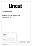
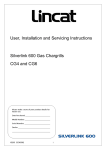
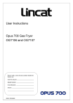
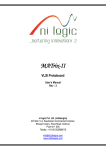
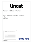
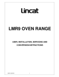
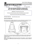
User, Installation and Servicing Instructions Opus 700 Electric Atmospheric Steamers OE7503 and OE7505 IS416 ECN3592 Dear Customer, Thank you for purchasing this Lincat product. This is just one of over 450 different items of catering equipment available which is constantly being extended and improved. Details are available from your local distributor or direct from us. Used for the purposes for which it is intended, and with careful maintenance as outlined in this User Guide, your Lincat product will give you years of trouble free service. IMPORTANT INFORMATION Please read all of the safety and operating instructions carefully before using this product. Please pay particular attention to all sections of this User Guide that carry warning symbols and notices. WARNING! This is a Warning symbol. This symbol is used throughout the user guide whenever there is a risk of personal injury. Ensure that these warnings are read and understood at all times. CAUTION! This is a Caution symbol. This symbol is used throughout the user guide whenever there is a risk damaging your Lincat product. Ensure that these warnings are read and understood at all times. NOTE NOTE: This is a Note symbol. This symbol is used throughout the user guide to provide additional information, hints and tips. IS416 ECN3592 2 CONTENTS Contents Page Customer Information………………………………………………………. 2 Warnings and Precautions…………………………………………………. 3 Technical Data………………………………………………………………… 4 Commissioning………………………………………………………………. 5 Check List of Enclosures…………………………………………………… 5 Installation…………………………………………………….………………. 6 User…………………………………………………………………………….. 7 Servicing ……………………………………………………………………… 8 Component Replacement ………………………………………….………. 9 Spare Parts List………………………………………………………………. 11 Fault Finding………………………………………………………………….. 13 Wiring Diagram……………………………………………………………….. 14 Service information………………………………………………………….. 15 Guarantee………………………………………………………….………….. 15 WARNINGS AND PRECAUTIONS It is mandatory that all appliances are installed, commissioned and serviced by a qualified and competent person as defined by the regulations in force in the country of installation. Failure to comply will invalidate the warranty. WARNING! This appliance must be installed by a qualified installation engineer in accordance with the installation instructions, and should conform to the following requirements: Do not obstruct or block the appliance flue. Installation must include sufficient ventilation to prevent the occurrence of unacceptable concentrations of substances harmful to health in the room in which they are installed. It is recommended that this appliance is sited under an extraction canopy for the comfort of the operator. After operation, some parts of the appliance will remain hot for a period of time. Please take care to avoid accidental burns. All equipment must be earth bonded. CAUTION! All equipment must be earthed to prevent shock. Do not connect directly to any flue, ducting or mechanical extraction system. Parts which have been protected by the manufacturer or his agent must not be adjusted by the installer or user. IS416 ECN3592 3 TECHNICAL DATA OE7503 Model Dimensions Overall height (mm) Width (mm) Depth (mm) Weight (kg) Usable oven capacity w x d x h (mm) Oven shelf size (mm) OE7505 1600 600 950 123 kg (Nett) 545 x 680 x 720 650 x 530 750 110 kg (Nett) 545 x 480 x 720 434 x 530 Water Connection Inlet Connection Pressure 15mm 20 – 1000kPa (0.2 – 10bar) Electrical Supply 9000W (3 Phase) 9000W (1 Phase) 3N~ +E 400V 50Hz 1N~ +E 230V 50Hz 39A IS416 ECN3592 4 COMMISSIONING PREPARATION Remove all packaging and protective coatings prior to installation. CHECK LIST OF ENCLOSURES Please ensure the following items are included with this piece of equipment: Model Warranty Card User Instructions OE7503 OE7505 Tick 1 1 SERIAL NUMBER NOTE Each appliance manufactured at Lincat has a unique identifying number found in the top right hand corner of the data plate, located behind the lower door on the LH chassis leg. Please record that number in the space provided should it be required for future reference. Serial Number MARK OF CONFIDENCE Every single product that leaves our factory bears a serial plate showing the assembler‟s initials. It‟s a mark of confidence we have in our people and our manufacturing process. IS416 ECN3592 5 INSTALLATION SITING The installer must ensure that all regulations are met and that there is an unobstructed minimum distance of 400mm from the top of the flue to the ceiling, which must be of noncombustible material. The appliance should be installed on a level surface ensuring the unit is stable and firmly located. It should be well lit and positioned to minimise the possibility of accidental touching. Any partitions, walls or kitchen furniture in close proximity must be of non-combustible materials and not be closer than 100mm from the sides and rear. A minimum clear space of 600mm to the front of the unit to allow for safe operation. WATER SUPPLY AND CONNECTION Install in accordance with BS EN 1717 and the National Water Regulations in Use. Connection is at the rear of the unit via a 15mm compression fitting with check valve. When making the connection to the appliance an isolating cock should be fitted into the supply line close to the unit, for emergency shutdown or servicing purposes. ELECTRICAL SUPPLY AND CONNECTION This appliance must be connected to the electricity supply by a qualified electrician, in accordance with the relevant regulations. This appliance should be connected to mains electricity via a suitable isolating switch, which should have at least a 3mm contact separation on all poles. The isolator should be easily accessible in the event of an emergency. Check that the power supply and the supply cable to be used is compatible with the rating of the unit. Connection of the supply cord is made at the rear of the unit behind the lower rear panel. Remove the protective cover using a small flat bladed screwdriver where indicated on the terminal cover housing and fit a suitable cable into the strain relief and then into the terminal inlet block. The unit is supplied for connection to a 3 Phase supply. Secure the earth to the indicated earth stud. OPERATIONAL CHECK Although all Lincat products are functionally checked during manufacture, commissioning must include an operational check of all controls. Operate the unit several times as per instructions, checking for correct and smooth operation. IS416 ECN3592 6 USER INSTRUCTION APPLIANCE USE This appliance is only for professional use and should only be used by qualified personnel. Ensure that the person responsible understands how to safely operate, clean and shutdown the appliance and is made aware of the position and operation of the isolating valves (water & electricity) in the event of an emergency. CONTROLS 1 4 3 6 2 5 7 1) 2) 3) 4) 5) 6) 7) Fig. 1 Drain Valve (Drip Trough) Re-Set Button (Safety Cut-Out Thermostat) Drain Valve (Oven Chamber) On-Off Switch (Green) Amber Neon Check Valve c/w Tap Water Inlet Tap WATER LEVEL WATER LEVEL PLATE Fig. 2 IS416 ECN3592 7 USER INSTRUCTION (cont.) OPERATING SEQUENCE Please ensure that the water and electrical isolation valves for the appliance are turned to the „OPEN‟ or „ON‟ position before attempting to operate the appliance. DO NOT OPERATE WHEN TANK IS EMPTY. Open the lower compartment door to gain access to the controls. Check water level is between indicator marks (see Fig.2). Press the green switch to the “ON” position, the switch and amber light will illuminate. All three heating elements will now be working. When the amber neon goes out the unit is up to cooking temperature. At this stage, only the maintenance (or rear) element is working. Note: Should the safety cut-out thermostat operate during normal use the unit will shut down. To proceed re-set the safety cut-out thermostat by depressing the red re-set button. The re-set button is located behind the lower compartment door on the underside of the controls cover. SHUT DOWN To turn the unit off completely, press the green switch to the “OFF” position and close water & electricity isolating valves. Drain tank and thoroughly dry inside of tank. Warning: When operating the controls behind the door care must be taken to avoid accidentally touching internal surfaces, which may become hot during normal operation. DRAINING OVEN CHAMBER Before draining it is recommended that the appliance be allowed to cool. To drain, place a suitable receptacle beneath the valve. Push catch to the left (Fig. 3) and open drain handle (Fig. 4). ENSURE THE CAVITY FILTER IS REMOVED AND CLEANED ON A DAILY BASIS, OR AS AND WHEN REQUIRED. Fig. 3 IS416 ECN3592 Fig. 4 Fig. 5 8 USER INSTRUCTION (cont.) OPENING THE STEAMER DOOR WHEN HOT: IMPORTANT – Do not fully open door when steamer is hot. First, slacken off door handle and allow steam to vent around door opening. Wait at least 15-20 seconds before slowly opening door fully. This precaution prevents a sudden discharge of steam into the operators‟ face. Always open door slowly and in two stages. CLEANING It is recommended that the appliance be drained and cleaned at the end of each working day in order to prevent any build-up of sediment and/or grease. Ensure the appliance is cool and the water and electricity supply is isolated before commencing cleaning. Open drain taps, remove oven furniture, filter (Fig.5) and clean all inner surfaces using a warm detergent solution. Rinse and dry thoroughly. After use wash the unit down with a warm detergent solution. Do not use any products containing chlorine or hydrochloric acid to clean stainless steel surfaces. Do not clean the appliance using a water jet. SERVICING For information on authorised service agents please see the section at the end of these instructions. ROUTINE SERVICE 1) Carry out a general check of the installation paying particular attention to the following: has the unit been installed using the correct supply cable? does the unit have separate isolation valves for water & electricity? is the connection to the supply via a suitable isolating switch? 2) Check all components for correct operation and replace where necessary, following the appropriate instructions. 3) Visually check the underside of the tank for any leaks.. 4) Ensure that the flue is clear. 5) Ensure that all water carrying components are sound and free from leaks. 6) Check the operation of the float valve. IS416 ECN3592 9 COMPONENT REPLACEMENT Ensure that the water and electricity supplies to the unit have been turned off before removing or dismantling any components. Element Drain the tank of water. From inside the lower compartment remove the control panel, secured by 5 screws. Disconnect the wires to the element (also remove the phial on the rear element) . Undo the element locking nut using a 45mm spanner/socket. Re-assemble in the reverse order. Switch From inside the lower compartment remove the control panel, secured by 5 screws. Disconnect the wires to the switch (noting their position). Squeeze the locating tabs together and remove the switch. Re-assemble in reverse order. Neon From inside the lower compartment remove the control panel, secured by 5 screws. Disconnect the wires to the neon (noting their position). Undo the locknut and remove the neon. Re-assemble in reverse order. Contactor From inside the lower compartment remove the control panel, secured by 5 screws. Disconnect the wires to the contactor (noting their position). Unclip the contactor from its mounting rail. Re-assemble in reverse order. Thermostat From inside the lower compartment remove the control panel, secured by 5 screws. Undo the 2 screws securing the thermostat to its bracket. Disconnect the wires (noting their position). Remove the upper back panel secured with 12 screws. Withdraw the phial through its gland and remove thermostat. Re-assemble in reverse order. Ensure that the thermostat phial is not kinked – has no sharp bends and is correctly located in its holder. IS416 ECN3592 10 COMPONENT REPLACEMENT (cont.) Safety Thermostat Unclip the safety thermostat phial from the rear element. From inside the lower compartment remove the control panel, secured by 5 screws. Disconnect the wires (noting their position). Working from the rear of the appliance remove both back panels. Withdraw the phial through its gland and remove safety thermostat. From the underside of the controls cover remove the 2 screws securing the safety thermostat. Re-assemble in reverse order. Ensure that the thermostat phial is not kinked – has no sharp bends and is correctly located in its holder. Lower Compartment Door Open door and remove 2 screws securing trim to chassis. Lift door away, together with securing trim taking care not to lose door bushes. Re-assemble in reverse order. At this stage the door is reversible. Upper Compartment Door Open door and remove oven furniture. Slacken off the screws securing the lower hinge block, whilst taking the weight of the door. The door can be lifted away. Take care not to lose door bushes. Re-assemble in reverse order. At this stage the door is reversible. IS416 ECN3592 11 SPARE PARTS LIST Description Shelf Shelf Hanger Door Bush Contactor Check Valve Element Float Valve Ball Float Magnetic Catch Neon (Amber) Door Seal Switch (Green) Safety Thermostat Operating Thermostat IS416 ECN3592 OE7503 OE7505 SH116 SH114 SH117 BU55 CO112 CV03 EL01 FL29 FL30 MC01 NE40 SE38 SW69 TH73 TH77 12 FAULT FINDING Explanation of the Control System The unit is fitted with a pre-set thermostat, together with a safety thermostat (neither are operator accessible). First open the water and electricity isolating valves. Turn on the water inlet tap (located in the bottom compartment ) this will allow water into the water reservoir then into the cooking chamber. Once the correct water level has been achieved, the green switch is pressed, the amber neon will glow and all three elements are energised. When the unit is up to temperature the front two elements are switched off and the amber neon goes out. The rear element remains energised. High limit thermostat operates Is the water level correct? Yes No Are the connections correct? Ensure Isolator valve is ON. Yes No Yes Check operating stat. Correct connections. Check float switch & solenoid No Yes Replace operating stat Manually reset over temp stat IS416 ECN3592 Manually reset over temp stat 13 No Turn ON & check level. Manually reset over temp stat. FAULT FINDING (cont.) Wiring Diagram IS416 ECN3592 14 SERVICE INFORMATION Electric catering equipment should be routinely serviced to ensure a long trouble free life. It is recommended that this appliance is serviced every 6 months by a competent engineer. For help regarding the installation, maintenance and use of your LINCAT equipment, please call:- LINCAT SERVICE HELP DESK +44 (0) 1522 875520 AUTHORISED SERVICE AGENTS We recommend that all servicing other than routine cleaning is carried out by our authorised service agents. We cannot accept responsibility for work carried out by other persons. Please quote both the model and serial numbers from the data plate attached to the unit. Give brief details of the service requirement. If possible please quote the product code of the part number you require. Work carried out under warranty will normally be undertaken only during normal working hours, i.e. Monday to Friday, 8.30 a.m. - 5.00 p.m. CONDITIONS OF GUARANTEE The guarantee does not cover:1) 2) 3) Accidental breakage or damage Operational misuse, wear and tear from normal usage, incorrect adjustment, or neglect. Incorrect installation, maintenance, modification or unauthorised service work. IS416 ECN3592 15 Notes IS416 ECN3592 16