1
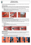
Safety-related checks and maintenance intervals
è All operating elements and fastening screws should be checked every month. The telescopic sliding plate should
remain free of dirt and sand.
è Please bear in mind that the screws and release handles etc. should be secured after each adjustment.
Please observe the following general safety instructions:
è When handling ThevoTwist, especially when setting up, please observe the recommendations in the user manual.
è Please keep packaging material away from children to avoid the risk of choking.
è We recommend that you adjust the seat depth and lower leg length according to the current body size of your child
at least every 3 months. If necessary, ask your therapist / orthopaedist for assistance.
è Please bear in mind to engage the locking device after adjusting the seat height, seat angle, and hip angle.
è Please be careful not to catch your fingers when carrying out adjustments.
è Be careful not to harm yourself when folding up the footrest or adjusting the seat height.
è IMPORTANT: Use the attached Allen key for all adjustments (Allen screw 3mm/0.1”).
è If you have doubts about the correct use of ThevoTwist consult your local dealer to avoid incorrect adjustments.
è For safety reasons accessories not mentioned in this user manual should be mounted by specialists only.
è Please do not overload your ThevoTwist and observe the maximum load capacity (see technical data).
è Do not leave your child unattended when getting in or off ThevoTwist. Excessive load of the footrest may lead to
slipping off or tipping.
è We recommend that you always secure your child with the 2-point pelvic belt (standard equipment) or another
retention belt (available as an accessory), and never leave the child unattended in ThevoTwist.
è Always lock the brake before placing or removing the child from ThevoTwist.
è Always lock the brake when the chair is stationary to avoid rolling.
è Avoid any obstacles in the way of the chair, do not push the chair into them.
è ATTENTION: Wet or flat wheels may affect the braking action. When stopping or halting for a longer period of time
you should apply the foot brake to prevent inadvertent rolling.
è When lifting ThevoTwist make sure to hold it at tightly welded or tightly screwed component parts only (frame tube at
front and rear wheels).
è Please avoid uneven ground, as this may cause ThevoTwist to tip over.
è Ground beams should be passed over only when the base frame is tilted to stand on the rear wheels (going upwards
– pull backwards, going downwards – lowering slowly).
è Wearing reflective clothing will increase your and your child’s visibility to other road users in the dark.
è Attaching heavy bags or string bags increase the danger of tilting. Use the basket in the J / A underframe.
è Please be careful when pushing on slopes to avoid ThevoTwist tipping over or rolling away, or your child falling out
of the chair.
è Parking ThevoTwist on slopes should be avoided.
è From time to time you should wipe off the dirt from the wheels. Use a damp cloth and make sure you dry thoroughly.
Do not use strong solvent.
è High solar radiation may lead to high surface temperature on the dark upholstery material.
è Do not expose the gas springs to high pressure or temperatures.
è Do not loosen or remove any screws unless otherwise stated.
è Keep ThevoTwist away from naked flames.
è Only one child should be transported in the rehabilitation stroller.
12
Purpose and use
The ThevoTwist size 1 and 2, seat together with a suitable underframe / undercarriage is appropriate for indoor and
outdoor transport of disabled children.
Risks and contraindications
Proper handling may avoid any use-related risks. No contraindications are known.
Technical data
ThevoTwist
size 1 seat
size 2 seat
Seat depth
Seating width
Back height
Lower leg length
Knee angle (adjustable in steps of 15°)
Hip angle
Foot angle
Seat tilt-in-space on J / A underframe
Size of footrest (w x d)
Overall dimensions (w x h x l)
Folded dimensions (w x h x l)
Carrying capacity
Weight
Seat turning range
19 - 30 cm / 7.5 – 11.8"
19 - 31 cm / 7.5 – 12.2"
47 - 65 cm / 18.5 - 25.6"
17 - 30 cm / 6.7 – 11.8"
90° to 180°
90° to 133°
78° to 100°
-15° to +45°
28.5 x 18 cm / 11.2 x 7"
38 x 78 x 64 cm / 15 x 30.7 x 25.2"
38 x 33 x 73 cm / 15 x 13 x 28.7"
35 kg / 77.2 lb
8,4 kg / 18.5 lb
180°
27 - 38 cm / 10.6 – 15"
25 - 36 cm / 9.8 – 14.2"
64 - 78 cm / 25.2 - 30.7"
25 - 36 cm / 9.8 – 14.2"
90° to 180°
90° to 145°
78° to 100°
-10° to +40°
33 x 21 cm / 12.9 x 8.3"
45 x 101 x 76 cm / 17.7 x 39.8 x 29.9"
45 x 35 x 91 cm / 17.7 x13.8 x 35.8"
40 kg / 88.2 lb
9,9 kg / 21.8 lb
180°
Setting up and assembly
The footrest is to be fixed to the knee joints. Place the grid joints one upon the other, and connect them with the screws
and the washers (coming from the inside) and wing nuts (coming from the outside).
Seat upholstery
Fix the two lower Velcro fasteners around the tubes of the footrest.
Engaging the seat unit
Insert the seat unit on the rear crossbar and engage forwards. The EASyS click-system snaps in automatically. (fig. 1)
Removing the seat unit
Push the EASyS click-lever under the seat unit forwards and take it off the underframe in forward direction.
Seat width
Loosen the hip seat guide screws from above using an Allen key and shift the hip guides accordingly. (fig. 2)
Seat depth
Loosen the front Allen screws (also for the adjustment of the seat width) on the seating surface and pull out the seat
plate. (fig. 3)
Tip:
For easy adjustment of the seat depth, grip the front edge of the seat with one hand and press against bottom
part of the backrest (concentric) with the other hand.
The depth of the hip guides can be adjusted, as well. Loosen the two screws, adjust the desired depth, and retighten the
screws. (fig. 4)
Back height
Loosen both knurled nuts at the back of the seat unit and adjust the desired height. (fig. 5)
Note:
The upper spring element should be removed for low back heights in order to facilitate an ergonomically
correct sitting posture. (s. Spring element)
Headrest
The height and angle of the headrest may be adjusted individually by loosening both wing nuts on the headrest. (fig. 6)
13
Backrest adjustment by gas spring
The release button at the top of the backrest has a safety lock. To unlock, slightly lift the release button and let it click
into place again after a quarter turn. Now, you can adjust the back angle. Hold the backrest with one hand and press
the release button down with the other hand. Adjust desired position by pushing or lifting the backrest. Then release the
button again. The seat unit automatically slides forwards on its rails, shifting the centre of gravity. Make sure to relock
the release button after each adjustment. (fig. 7)
Lower leg length
Release the locking device by loosening the knurled nuts on the right and left of the footrest. The height of the footrest
can be freely adjusted. (fig. 8)
Foot angle
Loosen the four screws on the right and left of the rear side of the footrest and adjust the desired foot angle. Re-tighten
the screws. (fig. 9)
Knee angle
Set the knee angle by loosening the side wing screws (on both sides). (fig. 10)
Tip:
The footrest can be flipped up to facilitate getting on and out of the stroller.
Spring element
The movable spring elements allow and facilitate the children’s individual mobility. (fig. 11)
Angle of rotation
Loosen the central Allen screw at the back of the seat unit and adjust the desired angle of rotation of the spring element.
Re-tighten the screw. (fig. 12)
Note:
To dismount the whole spring element, loosen the central Allen screw and remove the spring element
in forward direction.
Depth adjustment
In order to adjust the depth in the direction of the child, loosen the Allen screw for the adjustment of the rotation angle
(s. above). Now the upper and lower Allen screw at the back of the seat unit can be turned to the right, and the whole
spring element moves forward in the direction of the child. If the Allen screw is turned to the left, it moves back again.
After adjustment, the central Allen screw (for the rotation angle) should be re-tightened. (fig. 13)
Spring movement limiters
The red spring movement limiters are located inside the spring element. The displacement of the FGF track can be limited
as required.
To limit the spring travel, press the securing device inward until it engages into place. Press outward for loosening.
(fig. 14)
The adjustment of the spring movement limiters may be restricted when the belt bow is used. In such cases, slightly press
the spring element forward.
Tip:
Slightly lift the FGF track from the front for easier adjustment.
FGF track (flexible fibre glass track)
These tracks are made of fatigue-proof material using the latest fibre glass technology (pultrusion). Apart from high
durability, they also ensure optimal sitting comfort, which results in the child’s positive perceptive process.
Wing suspensions
The wing suspensions optimally fit the body contour of the children and transmit movement impulses. Each wing
suspension may be shifted or removed as necessary in order to ensure individual adaptation. To remove the wing
suspensions, press the top and bottom forward with both hands.
14
Recommendations for the adjustment of the ThevoTwist size 1 and 2, seat
1.
2.
3.
4.
5.
Place the child into the ThevoTwist.
Align the pelvis.
The spring elements can be adjusted to the child’s individual ergonomic requirements by regulating the angle
of rotation and depth of the spring elements.
The child’s care may be optimized with additional accessories.
The initial adjustment should be checked after 24 hours at the latest.
Cleaning, disinfection and care instructions
Cushions
All cushions may be removed in only a few steps. Both the fabric made of 100 % PES and the spacer fabric are top
quality textiles, washable at 40° C / 104° F. The fabrics are printed with non-poisonous, heavy metal-free dyes. Please
note that even high-quality fabrics may fade when exposed to permanent and intense sunlight. The cushion is made of
low flammability materials (BS 5852 part 1). (fig. 15)
Velcro fastening:
Occasionally, clean the Velcro ribbon with a brush in order to preserve the functionality of the Velcro fastening. Always
close the Velcro ribbons at washing.
Terms of guarantee / CE mark
Thomashilfen is certified in accordance with the ISO standard DIN EN ISO 13485:2003 and guarantees the quality of the
products they supply. Both material selection and processing meet the very highest of manufacturing standards. Every
single part is always subjected to final inspection.
Thomashilfen offers you a guarantee of 3 years for all frame parts, commencing on the date of purchase. This guarantee
incorporates all claims which influence functionality. Damages due to improper use (e.g. overloading), and natural wear
and tear are excluded.
ThevoTwist size 1 and 2, seat meets the requirements of the European standards EN 12182 and 12183 and is provided with a
CE marking.
Enjoy your ThevoTwist!
15