1
SECTION ONE
Reference Material/Terms
(1.0)
REFERENCE MATERIAL:
¾
DX2 User’s Manual and Field Maintenance Guide.
(1.1)
TERMS:
¾
CENTRAL CONTROL MODE indicates that two-way communications have been established
between the Evolution or DX2 controller and the Central Control PC. This means programming
data can be downloaded and uploaded, the Central PC can control all functions remotely, vital
controller information can be uploaded and stored on the Central PC, i.e. statistics, programs,
current limits, and flow limits.
¾
A SUBMASTER is a term used for an Evolution or DX2 controller, which is being operated in
conjunction with a Central PC. A Submaster is a controller that has specialized communications
capability. It can be set up for direct two-way communications with the Central PC either via
radio, telephone, or wire. Additionally, the Submaster is responsible for communications to any
Satellites that may be physically connected to it. Typical Submaster addresses are XXX-00, with
the –00 indicating a Submaster address.
¾
SATELLITE is a term used for any controller that is connected to a Central PC or a Submaster.
Yes, a Submaster is a Satellite, but a Satellite is not necessarily a Submaster. Typical Satellite
addresses are XXX-XX, with the –XX indicating a Satellite address. Also, -XX is any number
other than 00 from 01-99.
¾
The SATELLITE ADDRESS identifies each Satellite within a multiple controller system. The
address number is alternately displayed on the base screen of the controller.
¾
The MAIN PANEL assembly consists of a main microprocessor control board and an optional
sensor control board (attached to main board). Four cables from this assembly provide the
connections to the internal assemblies (Master Valve/Pump/Power, Communications (optional),
Sensor Terminal (optional), Station Output). Refer to DX2 User’s Manual page 2-12, for
assembly layout.
¾
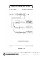
FLOW MAX is a multiple controller system configuration comprised of one Submaster and one or
more Satellites. This unique feature allows controllers to utilize a single point of connection to
share devices (flow sensors, master valves, pumps, etc.) and intelligently manage system
operation. Reference block diagram, FIGURE 1-1 of this Document.
Technical Bulletin 020
Sheet 2 of 18
3910-B Royal Avenue
Simi Valley, CA 93063
Tel: (805) 527-4498
Fax: (805) 527-2813