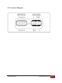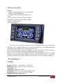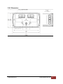
1
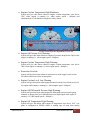
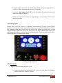
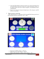
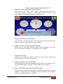
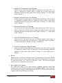
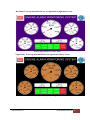
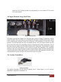
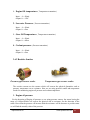
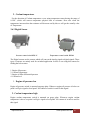
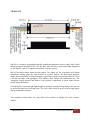
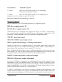
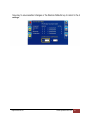
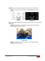
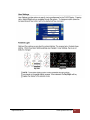
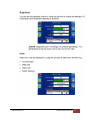
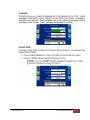
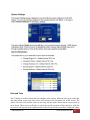
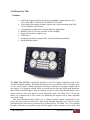
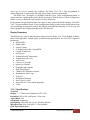
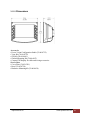
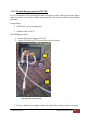
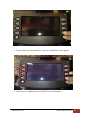
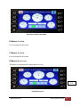
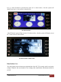
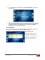
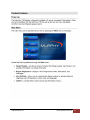
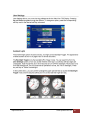
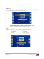
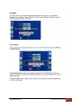
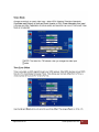
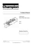
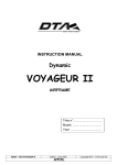
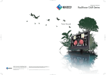
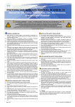
 User Manual Engine Safety Alarm Panel TABLE OF CONTENTS
Chapter 1: General Information
1.1 Illustrations………………………………………………………………………...4
1.2 Safety Requirements……………………………………………………………….4
1.3 General system safety practices…………………………………………................4
1.4 Replacing components…………………………………………………………......4
1.5 Routine Maintenance………………………………………………………………4
Chapter 2: General Safety Precautions
2.1 Electric Circuit Safety Precautions…………………………………………………5
2.2 Cable and Hoses Safety Precautions……………………………………………......6
2.3 Work Area Safety Precautions……………………………………………...............6
Chapter 3: System Description
3.1 Engine alarm monitoring system…………………………………………………....7
3.2 Block diagram representation: Engine AMS………………………………………..8
3.3 Block diagram description…………………………………………………………..8
3.4 Local Panel…………………………………………………………………………..8
3.4.1 Functions
1. Engine start/stop and emergency stop…………………………………9
2. Engine parameters monitoring…………………………………………10
3. Warning & Shutdown alarm monitoring………………………………11
4. Buzzer………………………………………………………………….13
5. Data Logging…………………………………………………………...13
3.4.2 Working Description……………………………………………………….14
3.5 Remote Panel…………………………………………………………………………15
3.5.1 Functions
1. Engine start/stop and emergency stop………………………………….15
2. Engine parameter monitoring…………………………………………..16
3. Warning and shutdown alarm monitoring……………………………...17
4. Buzzer…………………………………………………………………..19
5. Day/Night color change…………………................................................19
6. Service remainder settings………….......................................................21
7. Engine control status…………………………………………………....21
3.5.2 Working Description…………………………………………………………22
3.6 Engine mounted gauge panel plate………………………………………………..23
3.6.1 Analog Transmitter…………………………………………………………..23
Rajkot Marine LLC www.rajkotmarine.com 2 3.6.2 Resistive sensor………………………………………………………………..24
3.6.3 Digital Sensor……………………………………………………………….....25
3.7 Additional Sensor…………………………………………………………………......26
3.8 MeCAN………………………………………………………………………………..27
3.8.1 Maintenance and Operation……………………………………………………….29
3.9 XM 500…………………………………………………………………………………..31
3.9.1 Connector diagram………………………………………………………………..33
3.9.2 Wiring Diagram………………………………………………………………...34
3.10 Power View 450……………………………………………………………………...35
3.10.1 Specification……………………………………………………………………35
3.10.1 Dimension……………………………………………………………………....37
3.10.2 Downloading program in PV 450……………………………………………....38
3.10.3 Power View 450 Button Functions……………………………………………..42
3.10.4 Device Configuration Description……………………………………………..46
3.11 Helm View 750………………………………………………………………………….60
3.11.1 Specification…………………………………………………………………….62
3.11.2 Dimension……………………………………………………………………...63
3.11.3 Downloading program in HV 750……………………………………………...64
3.11.4 HV 750 Button Function……………………………………………………….68
3.11.5 Device Configuration Description of HV 750………………............................74
Chapter 4: Item List and Drawings
4.1 List of Items
4.1.1 Local Panel………………………………………………………………………….93
4.1.2 Engine mounted gauge plate………………………………………………………..94
4.1.3 Remote Panel……………………………………………………………………….94
4.1.4 AFT Panel…………………………………………………………………………..94
4.2 Drawings..............................................................................................................................95
Rajkot Marine LLC www.rajkotmarine.com 3 1. General Information
1.1 Illustration
This manual is intended for use by field engineering, installation, operation, and repair
personnel. Every effort has been made to ensure the accuracy of the information contained
herein. RAJKOT MARINE will not be held liable for errors in this material, or for consequences
arising from misuse of this material.
1.2 Safety Requirements
Personnel Training
All personnel performing installation, operations, repair, or maintenance procedures on the
equipment, or
those in the vicinity of the equipment, should be trained on ship safety, tool
operation, and maintenance to ensure their safety. Personnel should wear protective gear during
installation, maintenance, and certain operations.
1.3 General System Safety Practices
The equipment discussed in this manual may require or contain one or more utilities, such as
electrical, hydraulic, pneumatic, or cooling water.
¾ Isolate energy sources before beginning work.
¾ Avoid performing maintenance or repairs while the equipment is in operation.
¾ Wear proper protective equipment during equipment installation, maintenance, or repair.
1.4 Replacing Components
¾ Verify that all components (such as cables, hoses, etc.) are tagged and labeled during
assembly and disassembly of equipment to ensure correct installment.
¾ Replace failed or damaged components with parts mentioned in component list. Failure
to do so could result in equipment damage or injury to personnel.
1.5 Routine Maintenance
Equipment must be maintained on a routine basis. Failure to conduct routine maintenance could
result in equipment damage or injury to personnel.
Rajkot Marine LLC www.rajkotmarine.com 4 2. General Safety Precautions
2.1 Electric Circuit Safety Precautions
Certain safety precautions must be exercised regarding the electric circuits of the control system.
These precautions will prevent damage to equipment and injury to personnel.
¾ Personnel engaged in electrical work should receive proper instruction in accident
prevention and first aid procedures.
¾ An electric source power must be supplied at correct voltage, current, and phase to enable
safe and correct operation of equipment.
Exercise caution when working around exposed electrical conductors, terminals, and remotely
activated equipment. Avoid damage to the mating surfaces (flame path) of explosion-proof
Electrical junction boxes and the associated covers,
¾ Connections and circuit breakers. This will prevent fires or explosion that might result
from a spark during electrical switching.
¾ Do not override or tamper with electrical or mechanical interlocks and safety devices.
Before attempting any corrective action on the electrical circuit, verify that all electric
power sources have been removed from the circuit. Ensure that all electrical switches are
set to 'Off' and the appropriate breakers are set to 'Open'.
¾ Do not service or adjust the electrical circuits alone. Always verify that a qualified person
is present who can render aid in case of accident and who is familiar with emergency
shutdown procedures.
¾ Appropriate warning tags labeled 'Requiring Open Circuit Condition' shall be placed on
all necessary switches and circuit breakers to prevent accidental application of power to
units of the system during maintenance procedures.
¾ Wear suitable protective clothing while working within 4 feet of exposed electrical
equipment. Do not wear rings, wristwatches, or clothing with exposed metal buttons,
zippers, or fasteners.
¾ Metal handles of hand-held tools should be insulated by an approved taping, coating, or
sleeve method. Whenever it is necessary to work on electrical circuits or equipment in
wet or damp locations, dry, wooden (or similar non conducting material) platforms
should be provided to prevent the possibility of contact between the wet floor and the
workman's shoes.
Rajkot Marine LLC www.rajkotmarine.com 5 2.2 Cable and Hoses Safety Precautions
Protect all hydraulic hoses from cutting, scraping, pinching, abrasion, or any physical damage.
Route all cables and hoses outside of the crew's traffic patterns and away from mechanical
equipment. Welding or acetylene cutting must not be done near unprotected cables or hoses, as
this may result in damage to cables or hoses. Consideration must always be given to the
prescribed minimum bend radius for cables and hoses. Twisting or bending cables or hoses
beyond the minimum bend radius can damage the insulation, conductors, or reinforcing wire
shield.
2.3 Work Area Safety Precautions
Work in an area free of any dangerous obstructions, chemicals, or hazards. If any dangerous
obstruction is located overhead, to the side, or on the surrounding floor of the work area, the
hazard must be removed as safely and quickly as possible by appropriate personnel. If any
flammable materials are located in or are spilled within or in proximity to the work area, the
hazardous materials must be removed and cleaned from the work area. Flammable materials
include but are not limited to the following materials:
¾ Oily rags, paper products, or any combustible solid
¾ Kerosene, gasoline or any combustible liquid
¾ Oxygen tanks, acetylene tanks, or any combustible gas
Should any condition, situation, or circumstance occur that might pose serious hazard(s),
appropriate action must be taken to correct or remove the hazard(s) from the work area.
Rajkot Marine LLC www.rajkotmarine.com 6 3. System description
3.1 Engine Alarm Monitoring System
Features:
1.
2.
3.
4.
5.
6.
Monitor engine parameters and alarms locally and remotely.
Start/Stop engine locally and from remote (From wheel house).
Engine parameters and alarm logging into USB (From engine room panel).
Password protected service reminder settings.
Day/night color changing through key.
Easily programmable using USB stick.
Rajkot Marine LLC www.rajkotmarine.com 7 3.2 Blocck Diagra
am Representation: Engine AM
MS
3.3 Blocck diagram
m descripttion:
Above figure shows block diagraam representtation of enggine control panel system
m. This system is
designedd for controllling and monnitoring enggine system. Also it will display all important enngine
data (oil pressure, co
oolant tempeerature, speeed, etc ), saffety alarms and emergenncy indication in
wheel hoouse as well as in enginee room. Thiss system uses Murphy’s HV750 as a monitoringg cum
controllinng device wh
hich is very user friendlyy.
Rajkot M
Marine LLC ww
ww.rajkotmariine.com 8 3.4 Local Panel
Local panel serves the purpose of controlling and monitoring of engine necessary data
parameters. It incorporates engine start/stop and emergency stop in local (engine room) as well
as in remote (wheel house). Also it will shutdown engine when it will detect any safety alarm
(engine oil pressure low, coolant temperature high, engine over speed, etc). Panel uses CAN
open communication protocol for transmitting engine data to local and remote panel display
units. Communication process will be explained in detail in communication chapter.
Engine room panel
3.4.1 Functions:
1. Engine start/stop and emergency stop
•
•
•
Engine start/stop from local panel will be in action only when Local/Remote
selector switch is in “Local” position.
Green color PB mounted on front door of panel serves engine start function. Red
color PB mounted on front door of panel serves engine stop function. (Engine can
be stopped anytime from local or remote irrespective of Local/Remote selector
switch position.
During stop mode, stop relay will remain ON until engine speed drops below 100
rpm. Stop relay is resetted with XM500 DOUT1. DOUT 1 is turned on through
J1939 network by HV750 whenever engine rpm drops below 100 rpm
Rajkot Marine LLC www.rajkotmarine.com 9 •
Engine can be stopped in emergency through anyone of the emergency stop PBs
in local or remote panel.
2. Engine parameter monitoring
All the engine parameters are monitored by PV450 throughX500.
Following is the list of engine parameters which are monitored in local
panel
1st Screen display in Local panel (PV450)
2nd Screen display in Local panel (PV450)
•
•
•
•
•
•
•
Engine speed in RPM. ( Range 0---3000 rpm )
Engine oil pressure in PSI. ( Range 0---100 psi )
Engine coolant temperature in degree Celsius. ( Range 0---150C )
Engine oil temperature in degree Celsius. ( Range 0---150C )
Sea water pressure in BAR. ( Range 0---6 bar )
Engine coolant pressure in BAR. ( Range 0---6 bar )
Gear oil pressure in BAR. ( Range 0---40 bar )
Rajkot Marine LLC www.rajkotmarine.com 10 •
•
•
3.
Gear oil temperature in degree Celsius. ( Range 0---150 C )
Battery supply voltage in VOLTS. (Range 18---32VDC).
Engine running hours.
Warning and shutdown alarm monitoring
• Main Power Fail.
System will give this alarm whenever main power is cut-off.
• Backup Power Fail.
System will give this alarm whenever backup power is cut-off.
• Emergency Shutdown.
System will give this alarm whenever emergency push button is pressed from
local or remote panel and then after will shut down engine.
• Engine Over speed Shutdown.
System will give this alarm whenever engine speed is above 3500rpm.
Simultaneously it will shutdown engine for safety reason.
• Engine Oil Pressure Low Shutdown.
System will give this alarm whenever engine oil pressure drops below 10psi while
engine is running (i.e. when engine speed > 600rpm) and simultaneously it will
shutdown engine for safety reason.
.
Engine oil pressure shutdown indication in PV 450
Rajkot Marine LLC www.rajkotmarine.com 11 • Engine Coolant Temperature High Shutdown.
System will give this alarm whenever engine coolant temperature rises above
110C while engine is running (i.e. when engine speed > 600rpm) and
simultaneously it will shutdown engine for safety reason.
Engine coolant temperature high Shutdown in PV 450
• Engine Oil Pressure Low Warning.
System will give this alarm whenever engine oil pressure drops below 20psi while
engine is running (i.e. when engine speed > 600rpm ) .
• Engine Coolant Temperature High Warning.
System will give this alarm whenever engine coolant temperature rises above
100C while engine is running (i.e. when engine speed > 600rpm ) .
• Protection Override.
System will give this alarm whenever protection override toggle switch is turn
ON either from local or from remote panel.
• Engine Coolant Level Low Warning.
System will give this alarm when engine mounted coolant level switch gives level
low signal while engine is running (i.e. when engine speed > 600rpm ) .
• Engine Oil Differential Pressure High Warning.
System will give this alarm when engine oil differential pressure switch gauge
mounted on gauge plate gives differential pressure high signal while engine is
running ( i.e. when engine speed > 600rpm ) .
• Engine Oil Temperature High Warning.
System will give this alarm when engine oil temperature rises above 105C ( set
point is configured in XM500 which is reading eng oil temp from analog
Rajkot Marine LLC www.rajkotmarine.com 12 transmitter mounted on gauge plate) while engine is running ( i.e. when engine
speed > 600rpm ) .
• Engine Coolant Pressure Low Warning.
System will give this alarm when sea water pressure drops below 0.2bar ( set
point is configured in XM500 which is reading sea water pressure from analog
transmitter mounted on gauge plate) while engine is running ( i.e. when engine
speed > 600rpm ) .
• Seawater Pressure Low Warning.
System will give this alarm when engine coolant pressure drops below 0.2bar (set
point is configured in XM500 which is reading eng coolant pressure from analog
transmitter mounted on gauge plate) while engine is running (i.e. when engine
speed > 600 rpm ) .
• Gear Oil Clutched Pressure Low Warning.
System will give this alarm when gear oil clutched pressure switch gauge on
engine mounted gauge plate gives pressure low signal while engine is running (
i.e. when engine speed > 600rpm ) and gear is clutched IN.
• Gear Oil Temperature High Warning.
System will give this alarm when gear oil temperature rises above 105C (set point
is configured in XM500 which is reading gear oil temp from analog transmitter
mounted on gauge plate) while engine is running (i.e. when engine speed > 600
rpm ) .
4. Buzzer:
Whenever there is warning or shutdown alarm in system buzzer will turn ON. XM500
DOUT2 turns ON buzzer which in turn is turned ON by HV750 through J1939 network.
To silent buzzer there is black color PB mounted on front door of local panel.
5. Data Logging:
All the above engine parameters and alarms can be logged into USB from local panel.
For this one has to open local panel and plug USB stick into USB cable connected to
PV450 display unit.
Rajkot Marine LLC www.rajkotmarine.com 13 3.4.2 Working Description:
Local panel consist of four major components viz., MeCAN 1, MeCAN 2, XM500 and PV450.
These components read engine parameter from engine mounted gauge plate (details of gauge
plate will be covered later in this manual ) and display on PV450.
1. MeCAN 1: ( J1939 address = 8 )
MeCAN is a convertor that converts resistive/ switch input to CAN data. Engine oil
pressure low, coolant temperature high and over speed shutdown is through MeCAN
1. MeCAN 1 reads E.O.P.L and E.C.T.H shutdown signals from switches mounted on
engine gauge plate. MeCAN 1 provides these signals to PV450 in local panel and
HV750 in remote p-panel for monitoring of shutdown alarms. Signals are exchanged
through J1939 communication protocol.
2. MeCAN 2: ( J1939 address = 7 )
MeCAN 2 reads engine oil pressure, coolant temperature and speed from engine
mounted resistive senders and MPU (Magnetic Pick Up) sensor. Beside these
parameters it also provides battery voltage, engine running hours and warning signals
for E.O.P.L and E.C.T.H. Warning signal is triggered when engine speed is above
600rpm. MeCAN 1 provides these signals to PV450 in local panel and HV750 in
remote p-panel for monitoring of shutdown alarms. Signals are exchanged through
J1939 communication protocol.
MeCANs are preprogrammed from factory and cannot be reprogrammed.
Detail explanation for MeCAN is covered under MeCAN section which will come
later in this manual.
3. XM500: ( J1939 address = 6 )
XM500 reads engine oil temperature, sea water pressure, coolant pressure, gear oil
temperature, engine coolant level low, engine oil differential pressure high, gear oil
clutched pressure low from transmitters and switches mounted on engine mounted
gauge plate. It provides all data to PV450 and HV750 display unit through J1939.
Programming XM500 requires “XM500 Config” programming software along with
cable accessories.
Details for XM500 and procedure for programming is covered under XM500 section
later in this manual.
4. PV450: ( J1939 address = 242 )
PV450 is a display unit used for monitoring engine parameters, warning and alarms.
It reads data to be monitored from MeCANs and XM500 through J1939 network.
Also it communicates with HV750 in remote panel through J1939 network.
Rajkot Marine LLC www.rajkotmarine.com 14 It displays engine parameters in colorful gauge format and in text gauge format as
well so as to make monitoring clear and easy for analysis.
It provides “data logging into USB” screen for logging all engine parameters and
alarms into USB stick anytime.
Details for PV450 and procedure for programming is covered under PV450 section
later in this manual.
3.5 Remote Panel
Remote panel serves the purpose of controlling and monitoring of engine necessary data
parameters. It incorporates engine start/stop and emergency stop in remote (wheel house). Also it
will shutdown engine when it will detect any safety alarm (engine oil pressure low, coolant
temperature high, engine over speed, etc). Panel uses CAN open communication protocol for
transmitting engine data to local and remote panel display units. Communication process will be
explained in detail in communication chapter.
Remote panel in wheel house
3.5.1 Functions
1 Engine start/stop and emergency stop
•
Engine start/stop from remote panel will be in action only when Local/Remote
selector switch is in “Remote” position.
Rajkot Marine LLC www.rajkotmarine.com 15 •
•
2.
Green color PB mounted on front door of panel serves engine start function. Red
color PB mounted on front door of panel serves engine stop function. (Engine can
be stopped anytime from local or remote irrespective of Local/Remote selector
switch position).
Engine can be stopped in emergency through anyone of the emergency stop PBs
in local or remote panel.
Engine parameter monitoring
All the engine parameters are monitored by HV450 throughX500.Following is the list of
engine parameters which are monitored in local panel
1st Screen display in wheelhouse (HV750)
2nd Screen display in wheelhouse (HV750)
•
•
•
Engine speed in RPM. ( Range 0---3000 rpm )
Engine oil pressure in PSI. ( Range 0---100 psi )
Engine coolant temperature in degree Celsius. ( Range 0---150C )
Rajkot Marine LLC www.rajkotmarine.com 16 •
•
•
•
•
•
•
•
3.
Engine oil temperature in degree Celsius. ( Range 0---150C )
Sea water pressure in BAR. ( Range 0---6 bar )
Engine coolant pressure in BAR. ( Range 0---6 bar )
Gear oil pressure in BAR. ( Range 0---40 bar )
Gear oil temperature in degree Celsius. ( Range 0---150 C )
Battery supply voltage in VOLTS. ( Range 18---32VDC ).
Engine running hours.
Warning and shutdown alarm monitoring
• Main Power Fail.
System will give this alarm whenever main power is cut-off.
• Backup Power Fail.
System will give this alarm whenever backup power is cut-off.
• Emergency Shutdown .
System will give this alarm whenever emg push button is pressed from local or
remote panel and then after will shut down engine.
• Engine Over speed Shutdown.
System will give this alarm whenever engine speed is above 3500rpm.
Simultaneously it will shutdown engine for safety reason.
• Engine Oil Pressure Low Shutdown.
System will give this alarm whenever engine oil pressure drops below 10psi while
engine is running (i.e. when engine speed > 600 rpm ) and simultaneously it will
shutdown engine for safety reason.
.
Rajkot Marine LLC www.rajkotmarine.com 17 Engine oil pressure shutdown indication in HV 750
• Engine Coolant Temperature High Shutdown.
System will give this alarm whenever engine coolant temperature rises above
110C while engine is running (i.e. when engine speed > 600 rpm ) and
simultaneously it will shutdown engine for safety reason.
Engine coolant temperature high Shutdown in HV 750
• Engine Oil Pressure Low Warning.
System will give this alarm whenever engine oil pressure drops below 20psi while
engine is running (i.e. when engine speed > 600 rpm ) .
• Engine Coolant Temperature High Warning.
System will give this alarm whenever engine coolant temperature rises above
100C while engine is running ( i.e. when engine speed > 600rpm ) .
• Protection Override.
System will give this alarm whenever protection override toggle switch is turn
ON either from local or from remote panel.
• Engine Coolant Level Low Warning.
System will give this alarm when engine mounted coolant level switch gives level
low signal while engine is running (i.e. when engine speed > 600rpm ) .
• Engine Oil Differential Pressure High Warning.
System will give this alarm when engine oil differential pressure switch gauge
mounted on gauge plate gives differential pressure high signal while engine is
running ( i.e. when engine speed > 600rpm ) .
Rajkot Marine LLC www.rajkotmarine.com 18 • Engine Oil Temperature High Warning.
System will give this alarm when engine oil temperature rises above 105C ( set
point is configured in XM500 which is reading eng oil temp from analog
transmitter mounted on gauge plate) while engine is running ( i.e. when engine
speed > 600rpm ) .
• Engine Coolant Pressure Low Warning.
System will give this alarm when sea water pressure drops below 0.2bar (set point
is configured in XM500 which is reading sea water pressure from analog
transmitter mounted on gauge plate) while engine is running ( i.e. when engine
speed > 600rpm ) .
• Seawater Pressure Low Warning.
System will give this alarm when engine coolant pressure drops below 0.2bar ( set
point is configured in XM500 which is reading eng coolant pressure from analog
transmitter mounted on gauge plate) while engine is running ( i.e. when engine
speed > 600rpm ) .
• Gear Oil Clutched Pressure Low Warning.
System will give this alarm when gear oil clutched pressure switch gauge on
engine mounted gauge plate gives pressure low signal while engine is running (
i.e. when engine speed > 600rpm ) and gear is clutched IN.
• Gear Oil Temperature High Warning.
System will give this alarm when gear oil temperature rises above 105C (set point
is configured in XM500 which is reading gear oil temp from analog transmitter
mounted on gauge plate) while engine is running ( i.e. when engine speed >
600rpm ) .
4. Buzzer:
Whenever there is warning or shutdown alarm in system buzzer will turn ON. XM500
DOUT2 turns ON buzzer which in turn is turned ON by HV750 through J1939 network.
To silent buzzer there is key on HV750 with name “ Hide”. This screen will appear
whenever there is an alarm detected in system.
5. Day/ Night Color Change:
Day/ night color change is very much required in Marine application where light
intensity need to be reduced during night time using dimmer switch. In this system this
can be done just pressing one of the functional key of HV750. This key will function like
a toggle switch for day and night color change.
Rajkot Marine LLC www.rajkotmarine.com 19 Day Mode: Press top most function key on right hand of night mode screen
Remote panel startup screen in day mode.
Night Mode: Press top most function key on right hand of above screen
Remote panel startup screen in night mode.
Rajkot Marine LLC www.rajkotmarine.com 20 6. Service Reminder Settings:
Service reminder settings can be done in HV750. Total five service reminder are
provided, those are.,
i. Change engine oil.
ii. Change air filter.
iii. Change hydraulic oil.
iv. Service engine.
v. Service machine.
Only authorize person will be allowed to change the settings because there is password
protection for making any changes in settings.
7. Engine Control Status:
This screen shows important engine data which need to be monitored before starting, while
running and during engine shutdown conditions. It is present only in start up screen of HV750
display unit.
Rajkot Marine LLC www.rajkotmarine.com 21 i.
RUN:
This shows engine run and stop status. Status turns green whenever engine is running at
speed above 500rpm. Other when engine is stopped (speed below 100rpm) status is gray.
ii.
LOCAL MODE:
This shows engine control mode. When engine control is set to local from local panel
then status will turn green otherwise it turn gray showing that engine control is set to
remote from local panel.
iii.
PROT OVERRIDE:
This shows status of protection override toggle switch in local as well remote panel.
Whenever toggle switch is set in then the status will turn green otherwise it remains gray
showing that toggle switch is in OFF position.
iv.
COMMON ALARM:
This shows presence of any warning or shutdown alarm in engine AMS. It will turn
green whenever there is any alarm active in system otherwise it will turn gray indicating
that there is no alarm present in system.
v.
EMG STOP:
This shows status of emergency PB in local as well remote panel. Whenever EMG PB is
pressed irrespective of engine control mode it will turn green otherwise it turns gray
indicating healthy state of EMG PBs.
3.5.2 Working Description:
Remote panel consist of HV750 display unit, key switch, stop PB, EMG PB and a buzzer. Here
main component is HV750 and also it is master on entire engine AMS. HV750 is controlling
J1939 data communication within the network.
1. HV750: ( J1939 address = 127, CAN PORT 1 )
HV50 is a display unit used for monitoring engine parameters, warning and alarms. It
reads data to be monitored from MeCANs and XM500 through J1939 network. Also
it communicates with PV750 in local panel through J1939 network.
It displays engine parameters in colorful gauge format and in text gauge format as
well so as to make monitoring clear and easy for analysis.
It allows user to set service reminder for engine parameters. Also, only authorize
person is allowed to make changes in service reminder settings due to password
protection.
Day and night mode color changing option is provided through one of the functional
key.
Rajkot Marine LLC www.rajkotmarine.com 22 Details for HV750 and procedure for programming is covered under HV750 section
later in this manual.
3.6 Engine Mounted Gauge Panel Plate
Engine mounting Plate
This panel is present in the Engine side. The gauge plate consist of Gauges, Transmitters, and the
control Switches. Here two Gauges are present one for the Engine oil differential pressure which
is an switched gauge and other for the Gear oil pressure. The transmitters are used for Coolant
pressure, Sea water pressure and Gear oil clutched pressure. The two control switches are also
present that will used for the controlling of Engine oil pressure and Coolant Temperature. The all
the connections are going to the JB which present in the Gauge plate. The functions of gauges
which is used for the showing the Values respected pressure and controlling. The transmitter
which we used will converts the physical value to amps rating(4-20ma).The main function of the
Control switch which will having the specific set points pressure and temperature when the value
will reached the set point it will give the status to the respective system.
3.6.1 Analog Transmitters
Analog transmitter
The Analog transmitter converts physical quantity into 4—20mA signal. It can be pressure
transmitters, temperature transmitters, etc.
Rajkot Marine LLC www.rajkotmarine.com 23 1. Engine Oil temperature: ( Temperature transmitter )
Input : 4----20mA
Output: 0----150C
2. Sea water Pressure: ( Pressure transmitter )
Input : 4----20mA
Output: 0----6bar
3. Gear Oil Temperature: ( Temperature transmitter )
Input : 4----20mA
Output: 0----40bar
4. Coolant pressure: ( Pressure transmitter )
Input : 4----20mA
Output: 0----6bar
3.6.2 Resistive Senders
Pressure type resistive sender
Temperature type resistive sender
The resistive sensors are the sensors which will convert the physical Quantities such as
pressure, temperature etc to resistance. Here we are using pressure sender and temperature
sender for monitoring engine oil pressure and coolant temperature.
1. Engine oil pressure
For the detection of Engine oil pressure we are using pressure sensors. the sensor having the
range of 0-100psi.Which will convert the physical unit to resistance for the detection of the
status. Here when the pressure will increase then the resistance will be decrease as per this status
we will find the actually value of the pressure
Rajkot Marine LLC www.rajkotmarine.com 24 2. Coolant temperature
For the detection of Coolant temperature we are using temperature sensor having the range of
0-120C ,which will convert temperature physical unit to resistance .Here also when the
temperature increases then the resistance will decrease and by this we will get the actually value
of Temperature.
3.6.3 Digital Sensor
Pressure control switch KPS-31
Temperature control switch KPS 80
The Digital sensors are the sensors which will convert the Analog signal to digital signals. These
types of sensors are mainly used for switched application. In this we are using this sensors for
finding the below status.
1. Engine Oil pressure
2. Coolant Temperature
3. Engine oil filter differential pressure
4. Coolant level
1. Engine oil pressure low
Engine oil pressure switch is mounted on gauge plate. Whenever engine oil pressure is below set
point it will give signal to local panel. NO contact of switch is used for this signal.
2. Coolant temperature high
Engine coolant temperature switch is mounted on gauge plate. Whenever engine coolant
temperature is above set point it will give signal to local panel. NO contact of switch is used for
this signal.
Rajkot Marine LLC www.rajkotmarine.com 25 3. Engine oil filter differential pressure high
Engine oil filter differential pressure high signal is taken from switch gauge mounted on gauge
plate. Whenever engine oil differential pressure is above set point switch gauge contact will give
signal to local panel. NO contact is used for this signal.
4. Coolant level low
This signal is provided by coolant level switch mounted on engine coolant tank. Switch will give
a signal whenever coolant level is below its set point. NO contact is used for this signal.
3.7 Additional sensors
1. MPU: Magnetic Pick Up
M PU is used for monitoring engine speed. It takes engine rotation as an input and gives
PWM output as output to local panel. Further in local panel it goes to two MeCANs for
monitoring and shutdown purpose.
2. Thermocouple: ( Optional )
This sensor can be used for monitoring engine exhaust cylinder temperature. This can be
connected to XM500 thermocouple input. Drawing must be referred before connecting so
as to avoid any damage to XM500.
Rajkot Marine LLC www.rajkotmarine.com 26 3.8 MeCAN
MeCAN is a compact, encapsulated interface module that translates resistive sender, fault switch
and speed signals into SAE J1939 CAN bus data. MeCAN allows quick and simple integration
of ‘mechanical’, non-ECU engines into modern CAN bus systems.
MeCAN has three sensor inputs and one output. Two inputs are for oil pressure and coolant
temperature sensing, either by fault switches or resistive senders. The third input measures
engine speed, using MPU or charge alternator signal. Input signals are translated into SAE J1939
CAN bus messages with appropriate PGN address, data scaling and transmission rate. The
‘shutdown’ output operates and latches if the pressure, temperature or speed inputs deviate
outside preset fault limits.
A fourth input is connected and light enough for inclusion in many wiring harness, but can also
be surface mounted via four fixing holes. The case is fully sealed in epoxy resin for high impact
and environmental resistance.
Two standard versions allow use with either fault switches or Murphy ES series resistive
senders:
Rajkot Marine LLC www.rajkotmarine.com 27 Part numbers
Model/description
79.70.0096
.
MEC301-1 MeCAN I/O module, for use with Murphy
ES pressure & temperature senders
79.70.0097
MEC301-2 MeCAN I/O module, for use with pressure & .
temperature switches ( closing to negative DC on fault)
Electrical Connection & Mounting : MeCAN
Electrical Connection
MeCAN connection is via 9 color-coded flying leads ( see diagram on page 8)
RED: Power supply positive DC
BLACK: Power supply negative DC
Connect these wires to a smooth DC power supply in the range 7 to 35VDC. A 1amp anti surge
fuse is recommended in the DC line. MeCAN operates with negative earth/ground or fully
insulated DC systems. DO NOT use MeCAN with positive earth/ground systems.
VIOLET: Speed input signal
YELLOW/ GREEN: Speed input return
GREY: Speed calibration input ( 5 kOhm potentiometer )
Connect the violet wire to a magnetic pickup or speed sensor signal output. Connect the
yellow/green wire to the speed signal return wiring (or battery negative on ground/negativereturn systems). This input requires a speed signal of 3-30 VAC rms.
Before calibrating the speed input connect a 5kOhm potentiometer between grey wire and
battery negative DC. MeCAN allows adjustment for speed signals between 10 and 180 pulses
per engine revolution. The potentiometer can be removed in normal operation.
WHITE: Coolant temperature sender/switch input
ORANGE: Oil pressure sender/switch input
Part number 79.70.0096 is designed for use with Murphy ES series resistive senders. For best
measurement accuracy, use insulated return (2-wire) senders. Connect one terminal of each
sender to the appropriate MeCAN input lead; connect the other sender terminals to MeCAN’s
Sender Common (black) wire. Where 1-wire (negative DC/ground return) senders are used,
connect the black (sender common) wire to battery negative.
79.70.0097 is configured for use with low oil pressure and high coolant temperature switch
contacts that close to negative DC on fault. For insulated return (2-wire) switches, connect one
switch terminal to the appropriate MeCAN input; the second terminal from ach switch ( on 2Rajkot Marine LLC www.rajkotmarine.com 28 wire switches) or the body ground ( on 1-wire switches) must be connected to MeCAN’s
sender/switch common ( black) wire.
BLUE: Shutdown output
This open collector transistor output gives a negative DC signal, rated 250mA max, on detection
of fault conditions. The output latches following the fault condition, and can be deactivated by
removing the DC power supply. The output can be used to drive a warning lamp, audible alarm,
suppressed relay coil or ECU shutdown circuit.
3.8.1 Operation and Maintenance
Operation
MeCAN begins transmitting J1939 CANbus immediately after power-up. Data can be viewed
using a J1939 compatible display, e.g. The Murphy PV101, or used as a part of a J1939 control
system, eg. Murphy CANstart or CASCADE modules.
Engine oil pressure and coolant temperature
Model 79.70.0096 transmits pressure and temperature data when the resistive sender inputs are
within normal range. MeCAN also transmits appropriate J1939 SPN (Suspect Parameter Number
) and FMI ( Fault Mode Indicator) codes if:
•
•
•
Input resistance is out of normal sender range, e.g. open or short circuit.
Oil pressure drops below 20psi (warning message) and 10psi(shutdown/derate message)
Coolant temperature rises above 100C/212F (warning message) or 110C/230F(shutdown
message)
Model 79.70.0097 transmits pressure and temperature data in accordance with the input switch
position:
Oil pressure data
Coolant temperature data
Input switch closed( to –DC)
Input switch open
0 psi & SPN/FMI code
100 psi
105C / 221F & SPN/FMI code 90C / 194F
Oil pressure fault codes are not transmitted until 10 seconds after engine starting, once speed has
risen above 800 RPM.
Engine speed data
RPM data is transmitted whenever a valid speed signal is present ( above the minimum 3V rms).
If engine speed exceeds 3500 RPM, MeCAN also transmits the appropriate J1939 over speed
fault SPN and FMI code.
Rajkot Marine LLC www.rajkotmarine.com 29 Battery voltage
MeCAN measures its DC power supply voltage and transmits this as J1939 ‘electrical potential’
data (PGN 65271).
Hours run
MeCAN transmits ‘engine hours run’ data (PGN 65253). The hours run value is stored in nonvolatile flash memory and increases only while engine speed is above 500 RPM. To prolong
internal flash memory life, hours run data is updated at 3 minute intervals.
Maintenance
MeCAN contains no user-serviceable parts. Maintenance is therefore limited to the following
preventative checks:
•
•
Check that MeCAN electrical connections are secure.
Check that the case is mounted securely, with vibration and environmental exposure
minimized where possible. The case may be wiped with a clean, damp cloth. Do not use
cleaning solvents
Rajkot Marine LLC www.rajkotmarine.com 30 3.9 XM 500 :
Features
•
•
•
•
•
Adds I/O to J1939 Network
Works with Standard J1939 Display Modules
Wide Operating Temperature range
Industry standard Deutsch enclosure and connectors
Custom programming available
• Easy-to-use Configuration Tool available
The XM500 Module is a configurable Input/Output (I/O) module designed to bring analog and
digital inputs and output onto the SAE J1939 Controller Area Network. The XM500 Config Tool
provides a user friendly interface allowing the user to create or change the configuration used on
the XM500 module.
XM500 is ideally suited to bring the additional information you need onto the J1939 CANbus,
and can be configured to broadcast fault codes and activate digital outputs per input condition
such as Fuel Level Low, Hydraulic oil Temperature High, etc. Because the XM500 broadcasts
information using the J1939 standard protocol, the information can be displayed using standard
J1939 display modules, such as the PowerView PV101.
In this application XM500 is used for transmitting Gear Oil Temperature, Gear Oil Pressure,
Coolant Pressure, Sea Water Pressure, Engine Oil Temperature, Exhaust Temperature (
Rajkot Marine LLC www.rajkotmarine.com 31 Thermocouple I/P can be used), Engine Oil Differential Pressure High, etc onto CAN bus
network for displaying on PV450 and HV750 respectively.
Specifications
Power Input: 8 to 28VDC
Operating Temperature: -40 to 85C ( -40 to 185F )
Digital Inputs: 4 – Ground or battery positive activation
Digital Outputs*: 2 Sinking (500mA)
*(outputs are NOT reverse polarity protected. Damage will occur if B+ is connected to the
outputs. Damage incurred from improper installation is not covered under the
manufacturer warranty policy)
Thermocouple Input: Type K and Type J
Analog Inputs:
1- Battery Supply Voltage (dedicated)
2- Configurable as 0-5VDC, 4-20mA, resistive senders or used as an additional Digital Input
Speed Sensing Input: Magnetic Pick-up (2 to 120VAC RMS from 30 to 10,000Hz )
Communication Ports: CAN J1939
Product Weight: 10 ounces
Shipping Weight: 12 ounces
Shipping Dimensions: 4” X 6” X 2”
Note:
1. When the thermocouple input is used, only 5 resistive, 4-20mA, 0-5VDC can be used
instead of 7.
2. Analog inputs can be exchanged for digital inputs (battery ground activation only),
for a total of eleven digital inputs.
3. Other resistive senders can be supported.
Rajkot Marine LLC www.rajkotmarine.com 32 3.9.1 Connector Diagram :
Rajkot Marine LLC www.rajkotmarine.com 33 3.9.2 Wiring Diagram :
Rajkot Marine LLC www.rajkotmarine.com 34 3.10 Power View 450 :
Features
• Compact CAN-based display to fit your application
with freely configurable design
• Customize the bezel, buttons, I/O interface and
more
• Easy-to-use Power Vision Configuration Studio
• Bonded LCD screen viewable in direct sunlight
• Rugged / Reliable Design
• Endless possibilities
The Power View 450 display features a freely configurable design. Any of the major
components can be custom engineered to meet your exact needs. It’s an incredible amount of
customization with minimal non-recurring engineering costs.
You can change the shape of the bezel and buttons. You can rework the I/O board to add extra
inputs. You can add custom graphics and company branding to the interface.
The Power View 450 display is compatible with Power Vision Configuration Studio, so you can
continue to make quick and easy changes to the display. The PV450 display is also highly
durable. See the full specs on the back of this sheet for a full overview of its technical features.
3.10.1 Specifications
Technical
Display: Bonded 4.3” color transmissive TFT LCD
Resolution: WQVGA, 480 x 272 pixels, 16-bit color
Aspect Ratio: 16:9
Orientation: Landscape or portrait
Backlighting: LED, 500-650 cd / m2 (30,000 hr lifetime)
Microprocessor: Free scale iMX35 32bit, 532Mhz
QNX Real-Time Operating System
Rajkot Marine LLC www.rajkotmarine.com 35 Flash Memory: 256 MB (expandable to 8GB)
RAM: 128 Mbytes DDR2 SDRAM
Operating Voltage: 6-32 VDC, protected against reverse polarity and load-dump
Power Consumption: 10W max
CAN: Two CAN 2.0B; optional NMEA 2000 isolation
RS-485: 1 MODBUS Master/Slave
Video input (Optional): Two NTSC/PAL input channels with one displayed at a time.
Protocols: J1939, NMEA 2000, CAN open
Connection: 4 Deutsch DT 6-pin connectors
Keyboard: 8 tactile buttons
USB 2.0 host (full speed), optional OTG support
Output: (1) Open-drain, capable of syncing 500 mA
Input: (1) Resistive, 0-5 V, or 4-20 mA (software configurable)
Real-time clock with battery backup
Environmental
Operating Temperature: -40°C to +85°C
Storage Temperature: -40°C to +85°C
Protection: IP 66 and 67, front and back.
Emissions and Immunity: Electromagnetic Compatibility: 2004/108/EC
EN 61000-6-4
EN 61000-6-2 (immunity)
EN 501121-3-2
EN 12895
J1113/2, 4, 11, 12, 21, 24, 26 and 41
Vibration: Random vibration, 7.86 Grms (5-2000 Hz), 3 axis
Shock: ± 50G in 3 axis
Additional Options
LCD Touch screen (projected capacitance) capability
Rajkot Marine LLC www.rajkotmarine.com 36 3.10.2 Dimensions
Rajkot Marine LLC www.rajkotmarine.com 37 3.10.3 Downloading program into PV450:
PV450 configuration can be downloaded either with laptop or with a USB stick. But since laptop
and its accessories is not easily available when required we will focus on USB stick downloading
procedure.
Requirements:1. 1GB USB stick of any manufacturer.
2. USB data cable for PV450.
Downloading procedure:1. Switch off the power supply of PV450.
2. Connect USB stick to PV450 as per shown in below image.
Connecting USB stick to HV750
3. Press two function keys together as shown in figure before turning on the power supply.
Rajkot Marine LLC www.rajkotmarine.com 38 4. Do not release the keys until device is power up and below screen appears.
5. Once device is completely power ON below screen will appear.
Rajkot Marine LLC www.rajkotmarine.com 39 6. Now press the key show in above image then below screen will appear.
7. Again press the same key as shown in above image to start downloading process. Once
downloading starts below screen will appear.
Rajkot Marine LLC www.rajkotmarine.com 40 8. Above image shows downloading under process and once downloading completes
following screen will appear.
9. After this device will once again reboot and then start-up screen will appear. With this
downloading process is completed.
Rajkot Marine LLC www.rajkotmarine.com 41 3.10.4 Power
P
view
w 450 Buttton Functtions
This PV 450 has eight functio
onal buttonss. These bu
uttons can be program
mmed based on applicatio
on requirem
ment. F1 Butto
on Not assiggned in this ssystem F2 Butto
on Not assiggned in this ssystem F3 Butto
on This buttton is prograammed for d
displaying previous screeen. F
F3
ay in PV 450
2nd SScreen displa
Rajkot M
Marine LLC ww
ww.rajkotmariine.com 42 For eg: if above screen appears and user press this button then below screen will be displayed. 1st screen display in PV 450 F4 Button: Also called Menu Button This button is programmed for displaying device configurations screen . From this menu user
can make modification in device settings like brightness, date and time, J1939 source address,
monitoring parameter units, etc. Details on this are provided later under PV450 device
configuration descriptions.
User can enter into this screen by pressing F4 button on 1st screen.
F4
1st screen display in PV 450 Following screen will be displayed. Rajkot Marine LLC www.rajkotmarine.com 43 Device configuration screen in PV 450 F5 Button Not assigned in this system
F6 Button Not assigned in this system
F7 Button This button is programmed for displaying next screen. F7
1st Gauge display screen in PV 450 For eg., if above screen appears and user press this button then below screen will be displayed.
Rajkot Marine LLC www.rajkotmarine.com 44 2nd screen Gauge display screen in PV 450 F8 Button Not assigned in this system
Rajkot Marine LLC www.rajkotmarine.com 45 3.10.5 Device Configuration Description in PV 450: Rajkot Marine LLC www.rajkotmarine.com 46 Rajkot Marine LLC www.rajkotmarine.com 47 Rajkot Marine LLC www.rajkotmarine.com 48 Rajkot Marine LLC www.rajkotmarine.com 49 Rajkot Marine LLC www.rajkotmarine.com 50 Rajkot Marine LLC www.rajkotmarine.com 51 Rajkot Marine LLC www.rajkotmarine.com 52 Rajkot Marine LLC www.rajkotmarine.com 53 Rajkot Marine LLC www.rajkotmarine.com 54 Rajkot Marine LLC www.rajkotmarine.com 55 Rajkot Marine LLC www.rajkotmarine.com 56 In this menu F1 button is used for log in to the System settings .F2 is used for log in to
Service reminders. And also the F3 soft button will helps to log in Date and time setting
screen. Below explaining about the Sub menu functions.
Rajkot Marine LLC www.rajkotmarine.com 57 Date and Time The F3 button is used for setting the time and date in the system. When the user log in to the date
and time setting screen, here two arrows will present in the left hand side of the screen. The
yellow UP arrow will used the cursor to move up ,and the yellow Down arrow is used cursor to
move down. These arrows will helps to select the specific position of date and time. And also
two arrows will present in the right hand side of the screen which will used for editing the values
Rajkot Marine LLC www.rajkotmarine.com 58 of date and time. The F5 Soft button has the function of saving the reset values. Below showing
the Date and Time Screen.
Date and Time Screen in PV 450 Rajkot Marine LLC www.rajkotmarine.com 59 3.11 Helm View 750 :
Features
•
•
•
•
•
•
•
•
ABS Type Approved display for Marine and Offshore Applications on ACC,
ACCU and ABCU Classed Vessels (Model HV750 only)
Color display for modern electronic engines and vessel monitoring using SAE
J1939 Controller Area Network
Customizable for additional Commercial Marine applications
Bonded 7-inch LCD screen viewable in direct sunlight
Rugged design that is simple to use
Video input
Configuration Software option offers virtually unlimited possibilities
Blackout Mode Option
The Helm View HV750 is specifically designed to meet the engine monitoring needs of the
Commercial Marine industry. Its durable design and easy to use interface offers a complete view
of your vessels engines. Monitor propulsion, auxiliary, transmission, and genset engines all on
one display. It is equipped with the ability to switch between Day and Night mode operations
and even has a blackout option. There are multiple screens to choose from and the ability to turn
screens on/off to meet your specific marine application needs. The Helm View 750 has the
ability to be connected to a video camera for monitoring the engine room or other important
areas of the vessel.
This multi-functional display allows you to monitor multiple engines, transmissions, fuel
usage, and more using only one device, thus greatly reducing operating costs. It has ten tactile
push buttons that can easily be pressed with or without gloves. The Helm View 750’s sunlight
viewable, full-color screen makes seeing life-like gauges, alarm warnings, service codes, and
Rajkot Marine LLC www.rajkotmarine.com 60 video easy to view in virtually any condition. The Helm View 750 is fully programmed to
display Diagnostic Trouble Codes showing critical alarms and text explanations.
The Helm View 750 display is compatible with the Power Vision Configuration Studio so
custom software configurations can be quickly developed. With the Power Vision Configuration
Studio it is easy to define the user interface screens, monitoring
Requirements and specifications those are unique to the Commercial Marine industry. The Helm
View 750 paired with the Power Vision Configuration Studio extends custom configuration from
only monitoring to equipment control, data logging, and additional alarming. You can even add
custom graphics and company branding to the user interface.
Display Parameters
The following are some of the parameters displayed by the Helm View 750 in English or Metric
units (when applicable, consult engine or transmission manufacturer for SAE J1939 supported
parameters).
• Engine RPM
• Engine Hours
• System Voltage
• % Engine Load at the Current RPM
• Coolant Temperature
• Oil Pressure
• Transmission Oil Temperature
• Transmission Oil Level
• Tank Levels
• Course over Ground*
• Speed over Ground*
• Longitude and Latitude*
• Real Time Display*
• *NMEA GPS Antennae required
• Instantaneous Fuel Usage
• Trip Fuel
• Navigational Bearing
• Active Service codes
• Stored Service Codes (when supported)
• Video
3.11.1 Specifications
Technical
Display: 7” / 178mm color transmissive TFT LCD
Resolution: WGA, 800 x 480 pixels, 16-bit color
Aspect Ratio: 16:9
Orientation: Landscape
Backlighting: LED, 400-500 cd / mC (50,000 h lifetime)
Microprocessor: Free scale iMX.31 32bit, 400Mhz
QNX Operating System
Rajkot Marine LLC www.rajkotmarine.com 61 Flash Memory: 2 GB
RAM: 128 Mbytes SDRAM
Operating Voltage: 8-35 VDC, protected against, reverse polarity and Load-dump
Power Consumption: 10w full backlight; 22w full backlight with heater (at Temperatures below
-10 °C)
CAN: 3 CAN ports according to CAN specification 2.0A or 2.0B; one port
Isolated according to NMEA 2000 (GPS)
RS485: 1 MODBUS Master/Slave port, PVA Gage
Video input: NTSC/PAL
Protocols: J1939, NMEA 2000 (GPS), CAN Open protocol support.
Connection: 5 Deutsch DT 6-pin connectors
Keyboard: 10 tactile buttons
USB 2.0 host (full speed)
Output Digital: (1) capable of syncing 500mA
Inputs: (3) 0-5 VDC analog inputs. (1) input configurable to support measurement
Frequencies from 2Hz - 10 kHz and PWM values from 0-100% Duty cycle.
Environmental
Operating Temperature: -40°C to +85°C (-40°F to +185°F)
Storage Temperature: -40°C to +85°C (-40°F to +185°F)
Protection: IP67, front and back.
Emissions: IEC 60945, 95/54/EC
Immunity: SAE J1113, ISO 11452
Vibration: Random vibration, 7.86 Grms (5-2000 Hz), 3 axis
Shock: +/- 50G in 3 axis
Mechanical
Dimensions: 8.37 x 6.0 in. (212.5 x 152.3 mm) landscape
Unit Depth: 3.57 in. (90.8 mm)
Case material: Polycarbonate back case
Mounting: Front or Rear
Optional Gimbals Mount available
Rajkot Marine LLC www.rajkotmarine.com 62 3.11.2 Dimensions
Accessories
• Power Vision Configuration Studio (78-00-0752)
• Visor Kit (78-00-0732)
• GPS Kit (78-00-0601)
• Gimbal Mounting Kit (78-00-0697)
• Contact FW Murphy for cable and wiring accessories
Service Parts
• Cover Plate (78-05-0701)
• Bezel (78-05-0720)
• Hardware Mounting Kit (78-00-0638)
Rajkot Marine LLC www.rajkotmarine.com 63 3.11.3 Downloading program into HV750:
HV750 configuration can be downloaded either with laptop or with a USB stick. But since laptop
and its accessories is not easily available when required we will focus on USB stick downloading
procedure.
Requirements:1. GB USB stick of any manufacturer.
2. USB data cable for HV75.
Downloading procedure:1. Switch off the power supply of HV750.
2. Connect USB stick to HV750 as per shown in below image.
Connecting USB stick to HV750
3. Press two function keys together as shown in figure before turning on the power supply.
Rajkot Marine LLC www.rajkotmarine.com 64 4. Do not release the keys until device is power up and below screen appears.
5. Once device is completely power ON below screen will appear.
Rajkot Marine LLC www.rajkotmarine.com 65 6. Now press the key show in above image then below screen will appear.
7. Again press the same key as shown in above image to start downloading process. Once
downloading starts below screen will appear.
Rajkot Marine LLC www.rajkotmarine.com 66 8. Above image shows downloading under process and once downloading completes
following screen will appear.
9. After this device will once again reboot and then start-up screen will appear. With this
downloading process is completed.
Rajkot Marine LLC www.rajkotmarine.com 67 3.11.4 Helm
H
View
w 750 Buttton Functiions
1st sscreen of HV7
750 after reb
boot/restart.
HV 750 have ten fun
nctional keys as shown above.
a
Functionns assigned to
o these keys are given ass follows;
F1 Butto
on: Servicce Remindeer Settingss Press F1 button for e
editing servicc reminders.. After presssing F1 below
w screen will appear for entering presetted p
password forr making chaanges in servvice remindeer settings. word entering
g screen for seervice remind
ders settings
Passw
User cann enter the password
p
usiing this screeen. Once coorrect passw
word is deteccted by system it
will dispplay service reminder seettings screen as shown below. If password
p
enttered is incoorrect
st
then systtem will disp
play main scrreen i.e., 1 screen.
Rajkot M
Marine LLC ww
ww.rajkotmariine.com 68 Selection of password digits can be done using F5 AND F6 buttons respectively. Individual
password digits can be increase or decrease using F5 AND F7 respectively. For entering
password into the system F1 button should be pressed and for cancelling it press F4 button
respectively.
When set and entered password matches then following screen will be displayed for editing
service reminders .
Sevice remainder screen in Hv 750 Details on editing service reminder is explained in further section. F2 Button: Disabled It is not assigned in this system
F3 Button: Disabled It is not assigned in this system
F4 Button: Next Screen This button is programmed for displaying previous screen.
Rajkot Marine LLC www.rajkotmarine.com 69 F4
HV 750 Screen No.2 For e.g., when F4 button is pressed from screen no.2 as shown above then the system will
display screen no.1 ( previous screen) as shown below.
HV 750 Screen No.1 Menu: HV750 Internal Settings This button is programmed for displaying device configuration screen. From this screen user can
modify system settings based on application requirement. Details about device configuration
screen is explained well in later section.
Device configuration Screen in HV 750 Rajkot Marine LLC www.rajkotmarine.com 70 F5 Button: Day/ Night Toggle This button is programmed to toggle between day and night color mode. By default system will
display day mode. When user will press F5 button from screen no.2 as shown below
F5
HV 750 Screen No.2 In Day Mode On pressing F5 button from screen no.2(day mode) as shown above, system will display same
screen in night mode as shown below. F5
HV 750 Screen No.2 In Night Mode On pressing F5 button from screen no.2 ( night mode) as shown above, system will display same
screen in day mode as shown below.
Rajkot Marine LLC www.rajkotmarine.com 71 HV 750 Screen No.2 In Day Mode F6 Button: Disabled It is not assigned in the system
F7 Button: Disabled It is not assigned in the system
F8 Button: Next Screen This button is programmed fro displaying next screen.
F8
HV 750 Screen No.1 Rajkot Marine LLC www.rajkotmarine.com 72 For e.g., when F8 button is pressed from screen no.1 as shown above, then the system will
display screen no.2 ( next screen) as shown below.
HV 750 Screen No.2 when F8 button is pressed from screen no.2 as shown above, then the system will display screen
no.3 ( next screen) as shown below.
HV 750 Screen No.2: Camera View Enter button: Save The enter button present at bottom on right hand side of the HV 750 is mostly used for saving the
settings. Whenever the user intends to save settings after modification, this button need tp be
pressed.
Rajkot Marine LLC www.rajkotmarine.com 73 3.11.5 Device Configuration Description of HV 750: Rajkot Marine LLC www.rajkotmarine.com 74 Rajkot Marine LLC www.rajkotmarine.com 75 Rajkot Marine LLC www.rajkotmarine.com 76 Rajkot Marine LLC www.rajkotmarine.com 77 Rajkot Marine LLC www.rajkotmarine.com 78 Rajkot Marine LLC www.rajkotmarine.com 79 Rajkot Marine LLC www.rajkotmarine.com 80 Rajkot Marine LLC www.rajkotmarine.com 81 Rajkot Marine LLC www.rajkotmarine.com 82 Rajkot Marine LLC www.rajkotmarine.com 83 Rajkot Marine LLC www.rajkotmarine.com 84 Rajkot Marine LLC www.rajkotmarine.com 85 Rajkot Marine LLC www.rajkotmarine.com 86 Rajkot Marine LLC www.rajkotmarine.com 87 Rajkot Marine LLC www.rajkotmarine.com 88 Rajkot Marine LLC www.rajkotmarine.com 89 Rajkot Marine LLC www.rajkotmarine.com 90 Rajkot Marine LLC www.rajkotmarine.com 91 Rajkot Marine LLC www.rajkotmarine.com 92 4. Items list and drawings
4.1 LIST OF ITEMS
4.1.1 Local Panel:
Rajkot Marine LLC www.rajkotmarine.com 93 4.1.2 Engine Mounted Gauge Plate:
4.1.3 Remote Panel:
4.1.4 AFT Panel:
Rajkot Marine LLC www.rajkotmarine.com 94 4.2 Drawings
Rajkot Marine LLC www.rajkotmarine.com 95