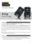
1
Water Drop Kit User Manual Author Peter Lin Editor Hugh Letheren Version 01 3/12/2013 Introduction The Water Drop Kit is an innovative, powerful, easy to use high speed water/liquid drop photography system. It consists primarily of a control unit (the controller) with LCD display and IR remote, plus water tank/bottle(s), solenoid valve(s) and drop nozzle(s) subsystems. It is innovative because of its IR remote feature which allows easy manipulation of parameters without making physical contact with the controller. The IR remote control also allows quick access to parameter settings, without the need to flip through a series of menus to find the parameter to be edited, just the single push of a button on the remote control. All parameter values can be digitally manipulated via up and down arrows on the remote, just like changing the volume on a modern digital stereo system. With a single push of a button on the IR remote control, the whole water/liquid drop process can be started once you have everything set up, remotely! This can make water/liquid drop photography much easier and less stressful. Without remote control, wires will be all over the place increasing the risk of poor connections and possibly creating hazardous situations, or even causing damage to equipment. Because of this remote control feature, the very few wires that are required can be grouped together at a central place, away from expensive equipment. It is powerful because, despite its small size, the controller can control up to three solenoid valves, referred to later as three channels. For each channel (solenoid valve), the number of drops, drop size (the same for all drops) and the delay between drops can be specified. In addition, it supports a special feature -- execution with a presettable automatic increment in flash delay. This feature allows water/liquid splashes to be captured at different stages such as during a collision Finally, the setting parameters can be saved to the controller so that when it is powered up next time, these parameters can be recalled easily. Hardware Specification The Water Drop Kit (TM) is made up of the controller, the liquid/water container bottle(s) and the solenoid valve(s) with specially designed nozzle(s). The controller has five output ports, three channels for solenoid valves, one camera port, and one flash port. It has one input that can be used to trigger the controller electronically. Illustration 1 -- WDK Controller Power Supply The Water Drop Kit (TM) can operate from 7.5V to 12V. The actual voltage and power rating (i.e. current rating) depends upon what type of solenoid valve is used because this power supply is used to drive them. For example, if a 12V DC solenoid valve (the supplied one) is used, a 12V DC power supply is needed. The supplied solenoid valve is a 12V DC 6VA pneumatic valve with 2.5mm orifice area, so the power supply provided is 12V DC, 24VA, which provides enough power to drive up to 3 valves and the controller. If the WDK controller is used without any solenoid valves connected it can be powered by batteries that can supply 7.5V to 12V DC to make use of its delay capability for sound photography, etc. It has a detachable screw-on type phoenix connector as shown in illustration 1. By default, it has a 2.1mm power jack extension attached. Output Ports There are three output ports for solenoid valves with a detachable screw-on type phoenix connector; they are marked as VR, VG, and VB as in illustration 1. Each solenoid valve output port can supply up to 800mA current and is thermally protected and limited at 1000mA -- when the current exceeds this amount, the port is shutdown. In most cases, this is more than enough to drive commonly available solenoid valves. The solenoid valve output port is also designed to drive the inductive load provided by the valve, with a clamping diode to protect the circuit from back EMF. Both the flash and camera ports are low current ports and can supply no more than 50mA. The camera port is a black 3.5mm stereo phone jack and it is marked CAM. The flash port is an orange 3.5mm stereo phone jack and it is marked FLASH as in illustration 1. Illustration 2 shows how the detachable phoenix connector works. Illustration 2 -- Phoenix Connector Input Port The only input port is simply a TTL level input with a 10K pull-up resistor. There is no amplification on this port. It is used to connect an external device to trigger the WDK controller electronically. This can be any device that can pull the input port to ground (logic zero). These include, but are not limited to Laser sensor. A simple photodiode or phototransistor with reverse biased configuration can be used. Sound sensor. When used with a sound sensor, the timer function is useful. Lightning sensor. You can use lightning as a water drop background. Radio triggers for flash. This is useful to remotely trigger the WDK controller when the IR remote is out of range or if the camera is in the bulb mode and the camera is used to send a out flash signal to the WDK to start the water drop process. IR Remote The IR technology used in the Water Drop Kit (TM) is very sensitive with excellent range -up to 3 meters (10 feet). It has been tested to have a range of 5 meters (15 feet) when the battery in the remote is fresh. Sometimes, even if the remote is not pointing at the controller, the IR signals can still be picked up, making it very easy and reliable to use. The IR remote control has 21 buttons on it as shown in Illustration 3 and it is powered by a single 3.0V lithium button battery CR2025. Illustration 3 -- IR Remote Control Remote Description Select Red Channel Select Green Channel Select Blue Channel Increase Parameter Value by One (+1) Decrease Parameter Value by One (-1) Increase Parameter Value by Ten (+10) Decrease Parameter Value by Ten (-10) Start Execution with Default Flash Delay Start Execution with Default Flash Delay + Advance Set Default Flash Delay for All Channels Set Advance for All Channels Set Camera Shutter Lag Value for All Channels Set Number of Drops for the Selected Channel (R, G, or B) Set Synchronization Delay for the Selected Channel (R, G, or B) Set Drop Size for the Selected Channel (R, G, or B) Set First Drop Delay for the Selected Channel (R, G, or B) Set Second Drop Delay for the Selected Channel (R, G, or B) Set Third Drop Delay for the Selected Channel (R, G, or B) Set the Size of First Drop for the Selected Channel (R, G, or B) Set the Size of Second Drop for the Selected Channel (R, G, or B) Set the Size of Third Drop for the Selected Channel (R, G, or B) Save Current Parameters to Permanent Memory in Controller. Typical Setup Water Drop System Setup Illustration 4 shows a typical setup for a complete single water drop system using the supplied equipment. Illustration 4 -- Typical Setup A -- Water Bottle B -- Bottle Clamp C -- Solenoid Valve and Nozzle Subsystem D -- Right Angle Bracket E -- Anodized Aluminum Bar F -- WDK Controller G -- PT-04 Wireless Flash Trigger (Optional) H -- Camera Tripping Extension Cable In the illustration above a tripod is used to hold everything and there is a sandbag on the far right leg of tripod to counterbalance the weight of the whole setup. If an alternative arrangement is used, it will make life a lot easier if all the wires are kept together and short: The controller should be mounted close to the valves to keep the valve wires short Keep the controller mounted on a uni-directional base so that it can be viewed from different angles. The tripod used to support the water drop system should be sturdy enough to hold everything together in a stable condition. The use of a sandbag as a counterweight on the tripod is recommended because, as the bottle is filled with liquid/water, the tripod may tilt. Camera and Flash Setup Before setting up the camera and flashgun(s) to the WDK controller, it is necessary to understand some basic high speed photography techniques. To capture high speed events, such as water drop collisions, a high speed camera with a super fast shutter can be used to capture the exact moment of interest. However, to capture good frozen motion water drop collision requires a shutter speed much higher than 1/10,000 of a second. Cameras with such a capability are very expensive and beyond the reach of many consumers. High speed events can also be captured using fast flash. Normally with this technique, the camera’s shutter is set to a very low speed or even kept open (bulb mode) for the duration of the capture. The aperture is kept very small so that without flash, the image captured is close to a black image. When the high speed event is synchronized with a very fast flash, the camera will have enough light from the flashgun(s) to properly expose an image of the high speed event. This technique is called stroboscopic photography. The WDK controller is designed around stroboscopic photography and its function is to synchronize a water drop collision with the camera and flash triggering. Illustration 5 shows a typical setup using a radio wireless trigger. In this setup, shutter speed does not have to be in bulb mode because the WDK controller can synchronize the camera shutter as well. This allows moderate ambient light to be used, making it a much easier environment in which to work. To start the process, the IR remote can be used. Here are some typical settings: Set the camera to manual focus mode, to prevent the delay introduced by the autofocus action. The camera shutter speed is set to 1/8 of second The camera aperture is set to f/9 with two flashguns. On the WDK controller, the camera lag is set to 200 (approximately 200ms) The camera is connected to the WDK controller’s camera output (black colored stereo jack in the middle) The flash output is connected to the transmitter of a wireless radio flash trigger. This radio trigger can be replaced with a wired cable to trigger the flashguns. Set the flash power to 1/128 and the ISO to 200. It may be necessary to vary flash power, aperture and ISO, all of which interact, to obtain the correct exposure. Illustration 5 -- Typical Camera & Flash Connection A - Camera port of the WDK controller B - Flash port of the WDK controller C - Flash wireless radio trigger (optional), it can be a wired cable. D - IR remote control E - Camera’s remote release port. Concepts & Glossary In most documents, the glossary is usually found at the end of documents, but since the Water Drop Kit (TM) is designed around some concepts that are critical to understanding how to achieve the best results and to better understand this manual, it is shown here. Concepts Related to WDK(TM) Channel -- a channel refers to a solenoid valve; they are named R channel, G channel, and B channel accordingly. These channel names loosely corresponds to Red, Green, and Blue for the liquid color each valve might control. But, for example, the R Channel does not have to control red water/liquid, it is merely a convention. The same applies to the G and B channels. To select a channel, press , , or Flash Delay -- the time delay between when the system starts and the flash output is triggered. This delay is independent of all other timing parameters. This parameter applies to the whole system and is independent of the channels. To set this value, press Execution -- an execution means a complete process from releasing water/liquid drops, delays, triggering the camera, and finally firing the flash. This is accomplished by pressing the button on the remote. Incremental Execution -- an execution process that has an increment parameter, namely Advance, added to the Flash Delay each time it is run by pressing . It is designed to help capture a sequence of similar events, such as a collision, each with a pre-defined increase in Flash Delay parameter. It is cumulative, meaning that every time Incremental Execution is run, the Advance value is added to the previous run. Advance -- a time increment parameter that is added to the Flash Delay when Incremental Execution is run. This parameter applies to the whole system and is independent of channels. To set it, press Camera Shutter Lag -- this is the delay between when camera is triggered and when the camera shutter is actually open. It is a physical function of the camera itself and varies from camera to camera (even for the same brand and same model). This parameter applies to the whole system and is independent of the channels. To set it, press Number of Drops -- this specifies the number of water/liquid drops for each Channel. For example, it is possible, in a multi channel system, to choose to produce two red liquid/water drops and only one blue drop. To specify this parameter, press . To change channels, press , , or First Drop Size -- this parameter specifies the size of the first water/liquid drop. Each channel can have its own value. To set it, press and to change channels, press , , or Second Drop Size -- this parameter specifies the size of the second water/liquid drop. Each channel can have its own value. To set it, press and to change channels, press , , or Third Drop Size -- this parameter specifies the size of the third water/liquid drop. Each channel can have its own value. To set it, press and to change channels, press , , or Sync -- this parameter sets the time delay from the Execution button press to the point when the drops are released for each channel. This is channel dependent -- each channel has its own value. To set it, press . To change channels, press , , or Drop Delay 1 -- this value specifies the time delay between the first drop and the second drop. It is irrelevant if Number of Drop is less than two (i.e, zero or one drop) and each channel can have its own value. To set it, press . To change channels, press , , or Drop Delay 2 -- this value specifies the time delay between the second and the third drops. It is irrelevant if Number of Drop is less than three and each channel can have its own value. To set it, press . To change channels, press , , or Drop Delay 3 -- this value specifies the time delay between the third drop and the fourth drop. It is irrelevant if Number of Drop is less than four and each channel can have its own value. To set it, press . To change channels, press , , or General Glossary Timeline -- a timeline is a sequence of events in chronological order. There are three timelines in the Water Drop Kit (TM) control system, namely: flash timeline, camera timeline, and water drop timeline. All three timelines are executed concurrently. Surface Tension -- is a contractive tendency of the surface of a liquid that allows it to resist an external force. The stronger the surface tension, the lower the Worthington jet will be. Surfactant -- is a compound, which when added to a liquid reduces surface tension. Flash Duration -- when an electronic flash fires, a pulse of light of predetermined length is produced, this time is called the flash duration. Modern portable electronic speedlites/speedlights use electronic switches and the power level is set by varying the flash duration. The longer the duration the higher output level. For water drop photography, the shorter duration, the less motion blur there is, producing a cleaner image. Stroboscopic Photography -- is a photographic technique which relies upon the flash power level to achieve the correct exposure. The shutter is kept open for a relatively long period of time and the aperture is kept small to reduce the contribution from ambient light. Camera Shutter Lag -- this is an inherent property of the camera being used. It refers to the time between the shutter being triggered, either by the button on the camera or an electrical command and when the shutter is fully open. It varies from camera to camera, even within the same brand and model. For a good DSLR it is about 200ms. Dropping Height -- the height from the opening of the drop forming nozzle to the catching surface. Worthington Jet, or simply Jet -- is the column of liquid which forms after a drop of liquid hits a liquid surface. Please see illustration 6. Illustration 6 -- Worthington Jet Understanding of Timeline In order to design a collision sequence, it is essential to understand how the Water Drop Kit (TM) controller controls timing sequences -- timelines. There are three timelines running concurrently – the flash firing timeline, the camera tripping timeline, and the water drop timeline. The camera timeline is dependent on flash timeline, but both camera and flash timeline are independent of the water drop timeline. Here are some important factors: The Flash firing timeline is the driving timeline -- it starts when the Execution button is pressed and ends with the flash being triggered, capturing the image, even if the water drop timeline is not finished. This means the flash timeline dominates both the water drop and camera timelines. The camera timeline is dependent on the flash timeline -- the camera is tripped when the timing reaches Flash Delay minus Camera Shutter Lag. Please note that if Camera Shutter Lag is larger than Flash Delay, the camera is tripped at the beginning of Execution and if the camera lag is set too short, the camera will not be tripped at all. The water drop timelines for all the channels are executed concurrently and are independent of each other. Synchronization between water drop timelines between channels is achieved by setting Sync timing delay for each channel – the Sync parameter for each channel can be considered as the delay between the start of Execution and the first drop for that channel. Because of Sync parameter and water drop timeline concurrency, the water drop timeline of each channel can be designed independently. When all water drop timelines reach their respective end for all channels, the controller simply waits for the flash timeline to end to finish the Execution. The delays between drops for a particular channel start when the previous drop finishes, i.e. when the solenoid valve closes after it has opened to start dropping. Techniques & Tips Water Solution Additives It is a well known secret amongst water drop photography enthusiasts that “thicker” water is easier to control. To make water “thicker”, additives can be mixed with water. The following are some commonly used additives: Guar gum powder. This is usually used to make ice cream thicker. Xanthan gum powder. This is also another additive used when making ice cream. Corn syrup. Glycerine. Milk. While it is not strictly an additive, milk is thicker than water and easier to control. The only purpose of these additives is to make the water drop solution thicker. Some of the additives make the resultant solution less clear and appear “cloudy”. The best and most often used is probably guar gum solution. Surface Tension Reduction The cohesive forces between liquid molecules are responsible for the phenomenon known as surface tension. The molecules at the surface do not have other like molecules on all sides of them and consequently they stick more strongly to those directly associated with them on the surface. This forms a surface "film" which makes it more difficult to move an object through the surface than to move it when it is completely submersed. When a water (or liquid) drop falls onto a water surface, if the surface tension is high, the water drop will not bounce up very far, so the jet coming back up will not be very high and the collision with a second drop (or a third, fourth . . .) will not be high, making it less attractive to capture. To reduce surface tension and increase dramatically the shape and dynamics of the collision, a surfactant -- an additive which reduces surface tension, is added to the catching tray. Here are some popular surfactants: Detergent Rinse Aid Coloring It is probably not very interesting to see plain water/liquid colliding, so the addition of color or colors to the dropping water/liquid and catching water/liquid can be very interesting. If different colors are added to the dropping and catching water, it could be even more interesting. Food dyes are commonly used for coloring purpose. Food dyes are: Safer. They are transparent. Easy to use. There is a large selection of colors available. They can be easily washed off. Flashgun Selection A flashgun is an electronic device that stores a large amount of energy in capacitors and then releases the stored energy in a short period of time. There are, for the purpose of water drop photography, basically two types of flashgun. The first type is often called studio strobes which are very powerful but very slow relative to the other type. These strobes are not suitable for water drop photography because their duration is very long, in the range from one to tens of milliseconds depending upon the power level. The other type, are often referred to as speedlites (Canon term), speedlights (Nikon term), or simply IGBT flash (other manufacturers). The way this type of flash works is to use an electronic device called an IGBT, to cut the flash duration short to achieve a defined power output level. Some of these flashguns can produce a 1/10,000 of second duration at 1/128 power output level. Therefore this is the type of flashgun that is well suited to this system. Depending upon the functionality and manufacturer, the price for this type of flashgun varies greatly. If the requirement is limited to water drop photography, then it is better to obtain so called “manual” flashguns which do not have the capability of following commands from a specific camera brand. You will always be short of flash power when doing water drop photography, so always obtain those with the highest output power possible and use them at their lowest power level, which will produce the shortest flash, and therefore freeze motion very well, which increases the sharpness of the captured images. Use of Wireless Flashgun Trigger There are two types of wireless flashgun trigger; one uses light, the other radio signals. These remote triggers can make a setup less messy and allow more flexibility in positioning the flashguns. Almost all modern IGBT based electronic flashguns have a built-in light sensor and will fire when it sees a single flash, often emitted by a so called master flash. This type of setup has one potential problem -- there is some delay caused by the sensor circuitry. If the master flash is part of the contributing light, this delay (latency) will cause a double or even multiple exposures within one frame. To solve the issue caused by light sensor latency, a lower power flash can be used, triggered by the WDK controller, but it should not be used to contribute any (or much less) light to the capture. The best way is to point it away from the scene. Another type of wireless trigger is based on radio signals. This type of trigger normally consists of two types of unit – a transmitter and receiver. One transmitter can drive multiple receivers. These remote triggers work well if used correctly. Just like the light sensor based trigger, there is a certain amount of delay between the transmitter and receiver. This delay can cause double, or multiple exposures, if each flashgun has its own receiver. The correct way to use it is to use only one transmitter and receiver pair and use the receiver to drive all the flashguns. Some radio triggers can only drive up to two flashguns, so in this case, specially designed electronic devices are needed. Regardless of what types of flashguns are used, the use of the same brand and same model flashguns for those that contribute to exposure is recommended. Better Practices In order to capture water drop collisions with good repeatability, it is critical to follow some basic practices: Patience-- as always, patience is a key element to success. After every drop, wait until the catching surface settles down. Ripples and disturbances in the surface will create different conditions for the next drop, making it really hard to get repeatable results. So wait until the surface has settled. Start with “simple” -- do not try to run before you can walk. Always start with simple things and take it step by step. Before trying to make a collision, set the number of drops to just one. It has been observed that the height of the Worthington Jet (water column bounced back up) varies with drop size. Try to obtain the best height for the first drop for a collision with the second, or third and so on. When satisfied with the jet height, increase the number of drops to two and capture the collision. Once collisions can be obtained consistently, vary the drop intervals (D1, D2, or D3) Adjust the distance between nozzle to catching water surface to observe the different effects. It may be necessary to go back to a single drop again to find the correct drop size. Surface Tension Reduction -- many beginners are quick to start capturing collisions but are then disappointed because it is very hard to produce a high enough jet to form a good collision with plain water. Reducing the water surface tension makes a big difference, like between night and day. Additives in the (dropping) Water Solution can also make it more manageable than without. Pre-Focus can greatly affect the sharpness of outcome. Use something that has a lot of texture and focus on it. Flash Setup and Configuration can also influence the outcome of the capture. If a one-to-many electronic device cannot be obtained and all the flashguns have to be triggered optically, put the optical master far away, pointing away from the collision so that it will not contribute any light to the exposure. Always clean up after a session When additives are added to the water solution in the bottles, they can cause the solenoid valve to become contaminated. Clean out the valves thoroughly. All electronic flashguns have high voltages (300+ volts) inside, impure water, particularly when filled with additives, can make it conductive, so make sure these liquids do not leak into the inside of the flashguns. Basic Skills All the exercises shown here are done with the setup shown in illustration 6 and all the pictures are taken with guar gum water solution in the water bottles and rinse aid in the catching water. In illustration 6, a large bowl is used as the catching container. However, many enthusiasts use a special tray in order to capture reflections of collisions. These basic skills are very important for the successful capture of a collision and for the more advanced exercises. Nozzle Preparation The nozzle is an integral part of the system and it needs to be cleaned often so that there is nothing clogging it or affecting the drops. A dirty nozzle can cause stray drops and make it very difficult to produce repeatable collisions, as drops will not follow the same path from one trial to another. Another important factor with the nozzle is air bubbles inside the nozzle. These bubbles cannot be seen with a metal or opaque nozzle but with the help of a semi-transparent plastic nozzle, it is easy to see how an air bubble is destroying the formation of clean water drops and changing the fall path. Illustration 7.1 shows air bubbles and what a well prepared nozzle looks like. Illustration 7.1 -- Preparation of Nozzle As can be seen in the illustration above, when a nozzle is first screwed onto the valve and the first few drops are produced, there is a large air gap between the nozzle opening and the inlet of the nozzle (outlet of valve). This air gap can cause abnormal drops, making it difficult for the drops to follow the same path. Even after quite a few drops, there may still be an air gap inside the nozzle. It is very hard to get rid of this air gap without following the proper procedure as described here. There are two ways to get rid of the air gap inside the nozzle: Pre-fill nozzle method Before screwing the nozzle onto the valve, fill it with water/liquid and block the opening of the nozzle so that liquid will not escape. Screw the nozzle onto the valve but only screw it in a little bit, enough to hold it onto the valve without falling. Put something at the opening of nozzle, partially blocking it, but leaving a tiny hole and start the dropping process. Water/liquid can escape from the tiny hole but not fully. Repeat the above process until there is enough water/liquid inside the nozzle. Now screw the nozzle all the way in but still blocking the opening of the nozzle fully. This action will cause the space inside the nozzle to shrink and the air inside can escape. Running water/liquid method Screw the empty nozzle all the way into the valve’s outlet. Press FD on the IR remote. Press R (or G or B) associated with the valve once and release. Press R (or G or B) and hold until water/liquid starts running out of the nozzle. Now partially block the nozzle opening, leaving a small hole to let water out a bit, but not fully. Do this until there is no air gap inside the nozzle as show in Illustration 7.1. Camera Preparation Plug in the camera tripping cable into the camera and WDK controller. If the camera being used has an auto focus feature, put your camera into auto focus (AF) mode. Prepare a focus aid, such as a small piece of cardboard, a piece of paper marked with a symbol, or anything with a lot of texture on it. While the camera is in auto focus (AF), put the focus aid at the same plane as the water would drop along. Once the camera is focused, put it into manual focus mode immediately. A plumb line (a length of thread with a small weight attached) blu-tacked to the water drop nozzle can be used to identify the point at which the drop will land. Of course, you can always put your camera into manual focus (MF) mode and focus on the focus aid manually -- adjusting the focus ring on the lens. Take a picture and see if the lighting conditions are satisfactory, increase or decrease aperture, ISO as well if necessary Move the flashgun(s) around to get a better background, this is a creative judgment and it is really up to the individual’s taste. Important note, the smaller the aperture, the sharper the image will be. Once everything is satisfactory, do not move anything, get ready for shooting! Flashgun Preparation Set the output of the IGBT Flashgun to its lowest possible setting to freeze the motion and thereby get a sharper image. If there is not enough light, add more flashguns. If it is not possible to add more flashguns, increase the power output level, but to no more than 1/32 for most flashguns on the market, based on experience. If a radio wireless flash trigger is used, it will probably be necessary to have a device to allow multiple flashguns to be hooked up to ONE receiver. If flashguns have to be triggered optically by one master flashgun, put the master flashgun far away and pointing away from the subject so that it does not contribute any light to the exposure. Please see illustration 8. Use of the same brand and model is recommended, preferably from the same manufacturing batch, for the optical slave flashguns so that they react to the trigger at the same time. Illustration 8 -- Comparison of Flash Setups Illustration 8 shows the difference between two flash setups. It compares two flash configurations. The configuration on left uses two flashguns, the first one is triggered by wireless radio and the other is triggered by the first one optically. As can be seen, it has significant double exposure. On the other hand, the configuration on the right uses three flashguns, the first one is triggered by wireless radio and acts as optical master and the other two are triggered by the first one (master) optically. However, the optical master flashgun is placed far away so, pointing away from the splash, so that it does not contribute any exposure to the final scene. The two flashguns which do contribute to the exposure are of the same brand and model. As evidenced by the comparison, the configuration on the right is much better. Getting a Worthington Jet from a Single Valve The first exercise is to get a Worthington jet as high as possible. It may be simple and easy to do but it is critical for any subsequent shoots. This exercise can be done with the naked eye, so there is no need to setup flashguns and camera. Initially, turn off the camera and flash trigger because it can be observed visually, with the naked eye. Fill the container bottle with water/liquid until its level is in the middle of the bottle. Set Drop Count, (press on you remote) to 1. Set First Drop Size (press ) to a moderate amount, for example, 40. Execute (press ) to see how high the Worthington jet is. If the jet is very low, increase drop size and try again. If a hollow sound can be heard or bubbles are forming on the catching surface, the drop size is too big so decrease drop size. Repeat until the height of the jet is satisfactory or the height is at peak -- when any attempt to increase it actually decreases it. If the height is still not satisfactory, try adding some surface tension reduction agent into the catching water/liquid. Alternatively, adjust the dropping height – the height from the nozzle mouth to the catching surface. Illustration 7 shows an example of this process. Illustration 7 -- Effect of Drop Size on Jet Height This illustration shows that as drop size increases, the height of the Worthington jet is also increases. Of course, when drop size increases to a certain point, the jet actually collapses and normally a hollow sound can be heard and bubbles form if the catching tray has surfactant. Note keep Flash Delay at a constant value so that there is no variation caused by it. There is an important thing to keep in mind during this exercise -- keep the water/liquid level in the container bottle at nearly the same level. If after many trials without a satisfactory jet height, add water to at least its original level. Learning the Effects of the Water Level in the Bottle In the previous exercise, an important note must be observed -- keeping the water level in the container bottle approximately the same. This is important as it has a significant effect on how the Worthington jet is formed. Now, instead of filling the bottle to the middle, fill it all the way up to almost full. The higher the water/liquid level in the bottle, the more pressure there is at the nozzle opening, producing a larger drop size which drops more quickly. It is less controllable than when the level in the bottle is lower. Instead of filling it full, fill it to about 1/4 full, this has the opposite effect on drops compared with a higher level in the bottle. It is much more controllable and produces less stray drops. Getting Two Drops to Collide From a Single Valve After getting a satisfactory Worthington jet, the next step is to get two drops colliding in mid air. However, during this exercise, the intention is to observe and grasp some of the key skills required for advanced collision capture – including the effects of Flash Delay, Delay 1, and Drop Size. So, it is recommended to do this exercise over and over again. Prepare the Worthington jet with a drop count of 1 to a satisfactory height, the skill learned from last exercise. Turn on the camera and connect the camera release port to the WDK controller Connect flashgun(s) or triggers to the WDK controller Adjust the Flash Delay to capture the tallest Worthington jet Start with some low value for the flash delay. Rule of thumb -- put in 350 if the height from the tip of the nozzle to the surface of catching water is 0.5 m If you are mathematically inclined, the formula is sqrt(H/4.9) where H is the height from the tip of the nozzle to the surface of the catching water measured in METERS If you are mathematically inclined, the formula is sqrt(H/16) where H is the height from the tip of nozzle to the surface of the catching water measured in FEET If the water drop is in mid air in the captured image, increase Flash Delay If the jet is NOT as tall as seen with the naked eye, increase Flash Delay Repeat until the tallest jet is captured with the camera. One trick here is to use the Incremental Execution feature of the WDK controller. Start with Flash Delay at some reasonably low value Set Advance to 5 Start pressing Incremental Execution (on the remote) repeatedly until the tallest jet is captured Set Drop Count to 2 Set Drop Size to be the same as the first drop Set Delay 1 (time delay between the first and second drops) to a moderate value. If you do not see a collision in the captured image: It is probably because the delay between drops is too long, so decrease it Or Flash Delay is too short, so increase it until at least the second drop can be seen in the captured image Again, Incremental Execution can be very helpful to capture the moment of collision correctly Illustration 9 -- Example of Using Incremental Execution Here is one example of Incremental Execution with Advance = 5. As can be seen in the picture, the second drop approaches the jet caused by first drop every 5 ticks (Advance) until it collides with the jet and forms a splash. As time goes by, the splash collapses, as can be seen in the last picture. Once the right Flash Delay and Delay 1 are found and the collision is captured by the camera, here are some more exercises which are very important for future captures: Increase or decrease Flash Delay and observe how it affects the shape of the collision. The longer the Flash Delay, the bigger the collision/splash until the point where Flash Delay is too long and the shape actually collapses and disappears. See Illustration 10. Increase or decrease Delay 1 and observe. The larger the value of Delay 1 is, the higher the collision is up the jet column until when Delay 1 is too large, there will be no collision at all. This effect is shown in Illustration 10. Another important factor is the Drop Size for the second drop. Vary it from small to large and observe the effect it has on the shape of collision. Illustration 10 -- Effect of Delay 1 on Height of Collision When the delay between the first and second drop (Delay 1) increases, the collision height increases as well. The above picture shows this effect. The Flash Delay should be increased by a similar amount to the increase in Delay 1.