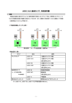
1
SoC Reference Kit User Manual
Fujitsu Microelectronics America, Inc.
Corporate Headquarters
1250 East Arques Avenue, M/S 333
Sunnyvale, California 94088-7470
Tel: (800) 866-8608 Fax: (408) 737-5999
E-mail: [email protected] Web Site: www.fma.fujitsu.com
© 2005. All rights reserved.
PN 5720-6104 Rev.1.1
SoC Reference Kit User Manual
TABLE OF CONTENTS
1.
1.1
1.2
1.3
1.4
Overview ...................................................................................................................................1
Reference Kit Content...............................................................................................................1
SoC Reference Board Specifications........................................................................................1
1.2.1 General..........................................................................................................................1
1.2.2 Power Supply ................................................................................................................3
1.2.3 Processor ......................................................................................................................3
1.2.4 Upper Media Access Control (UMAC) Processor Peripherals......................................3
1.2.5 Clocks............................................................................................................................3
1.2.6 I/Q Output......................................................................................................................3
1.2.7 Baseband and RF Interface Connector ........................................................................4
1.2.8 External Processor Interface Connector .......................................................................4
1.2.9 Debugger Board Interface Connector ...........................................................................4
1.2.10 RS232 Connector..........................................................................................................4
1.2.11 ARM Debug Connector .................................................................................................4
1.2.12 ARM Embedded Test Module (ETM) Connector ..........................................................4
SoC Baseband Board Specifications ........................................................................................4
SoC Debugger Board Specifications ........................................................................................4
2.
2.1
2.2
2.3
2.4
Quick Start Guide......................................................................................................................5
Host PC Requirement ...............................................................................................................6
How To Configure HyperTerminal ............................................................................................6
Installing Heatsink and Powering Up ........................................................................................8
Setting Up SoC Reference Boards for a Traffic Test................................................................8
2.4.1 Baseband Traffic Procedure .........................................................................................8
2.4.2 RF Traffic Procedure.....................................................................................................8
3.
3.1
Using the Reference Kit Software...........................................................................................10
Terminal Setup........................................................................................................................10
3.1.1 SoC Main Menu ..........................................................................................................10
3.1.2 System Configuration Menu........................................................................................11
3.1.3 RF Board Configuration Menu ....................................................................................12
3.1.4 ARM Subsystem Tests Menu......................................................................................14
3.1.5 802.16 PHY Tests Menu .............................................................................................16
3.1.6 Traffic Application Menu..............................................................................................17
3.1.7 Upgrade Menu ............................................................................................................18
3.1.8 Save and Restore Configurations Menu .....................................................................19
Appendix 1: Definitions and Acronyms ........................................................................................... A-1
Appendix 2: Reference Board Functional Description.................................................................... A-2
Appendix 3: Connector PinOuts ................................................................................................... A-15
Appendix 4: Reference Board Bill of Materials (BOM) ................................................................. A-32
Appendix 5: Reference Board Schematics ................................................................................... A-37
i
September 2005
SoC Reference Kit User Manual
1.
OVERVIEW
The System on Chip (SoC) Reference Kit is designed for Institute of Electrical Electronic Engineers
(IEEE) 802.16-2004/WiMAX product developers for evaluation of WiMAX solutions from Fujitsu.
The SoC Reference Kit includes the necessary software and hardware components to achieve a
cost effective, fixed Broadband Wireless Access (BWA) system solution for
•
Low-cost subscriber stations (SS),
•
Enterprise SS, and
•
Base stations (BS).
The Fujitsu 802.16 platform enables a BWA platform for SS or BS. It includes:
•
Compliance with IEEE 802.16-2004 standard specification.
•
Media Access Control (MAC) portability to different Real Time Operating System (RTOS).
•
MAC security sublayer for SS authentication and data encryption.
•
Multiple service class support to differentiate service quality.
•
Dynamic service management to activate the service class when needed.
1.1
Reference Kit Content
The SoC Reference Kit consists of a combination of hardware and software components. The three
(3) main components are the
•
SoC Reference Board with the 802.16/WiMAX SoC Integrated Circuit (IC) core processor,
•
Software package to run the SoC and the Reference Board, and
•
Software package to install the SoC Reference Kit as a half-duplex WiMAX SS.
Figure 1 shows the hardware components included in the SoC Reference Kit, while Figure 2
illustrates the relationships between hardware and software components of the SoC Reference Kit.
The SoC Reference Board has a high-density connector that can be attached to either a Baseband
Adaptor Board or an Radio Frequency (RF) Evaluation Board from SiGe Semiconductor.
Use two (2) SoC Reference Kits to create a simple point-to-point network, or purchase additional
SoC Reference Kits to expand to a point-to-multipoint network. Additional RF boards can be
purchased to evaluate other RF configurations (e.g., duplex mode or channel bandwidth). The
software included in the SoC Reference Kit allows the user to customize operational configurations.
1.2
SoC Reference Board Specifications
1.2.1 General
•
Duplexing: Half Duplex-Frequency Division Duplexing (HD-FDD) or Time Division Duplexing (TDD).
•
Channel BW: 1.75 to 20MHz.
•
Wire Interface: Ethernet 10/100BT.
•
Radio Interface: Baseband, 3.5GHz Band.
•
Operating Temperature Range: -40°C to +85°C.
1
September 2005
SoC Reference Kit User Manual
Figure 1: Hardware—SoC Reference Kit
Figure 2: Relationships between Hardware and Software—SoC Reference Kit
2
September 2005
SoC Reference Kit User Manual
1.2.2 Power Supply
•
Power Requirements: 15W Max standalone or 25W Max with external processor board.
•
Input: 48VDC.
•
Connector: 5.5mm OD, 2.5mm ID, Center Positive DC Connector.
•
Power Reset: Voltage supervisor resets processor when rails drop below 20% nominal value.
•
Power Sequencing: Voltage rails are sequence to requirements of processor.
1.2.3 Processor
One (1) Fujitsu MB87M3400 WiMAX SoC.
1.2.4 Upper Media Access Control (UMAC) Processor Peripherals
•
Processor: ARM 926 internal to SoC.
•
Memory:
– Synchronous Dynamic Random Access Memory (SDRAM): 128Mb 4Mx32 Micron
MT48LC8M32LF-F5-10.
– Flash: 4Mb.
•
Ethernet Physical Layer (PHY):
– AMD 79C874.
•
General Purpose Input/Output (GPIO) Light Emitting Diode (LED) status:
– LED status indicators for each 24 GPIOs for software development.
– Dual In-line Package (DIP) switch pull down for 10 GPIOs for software development.
1.2.5 Clocks
•
Clock Source: 20MHz Voltage Controlled Temperature Compensated Oscillator (VCTCXO),
±10ppm control, ±4.5ppm stability.
•
Front End (FE) PHY Clock: Generated by programmable Direct Digital Synthesis (DDS),
Analog Devices AD9834.
•
Reference Board VCTCXO can be bypassed by a jumper when RF Boards are used.
1.2.6 I/Q Output
•
Transmit (Tx) Analog Output:
– 10mA outputs requiring 75ohm termination resistor.
– Differential outputs.
•
(Receive) Rx Analog Input:
– 0.5VPP inputs.
– 0.55V common mode differential inputs.
– 1.2Kohm impedance.
•
Digital to Analog Converter (DAC) Outputs:
– 10-bit DAC outputs for option of using external DACs.
– Outputs provided on 38-pin Mictors for logic analyzer access.
•
Digital Analog to Digital Converter (ADC) Inputs:
– 10-bit ADC inputs for option of using external ADC.
– Inputs provided on 38-pin Mictors for logic analyzer access.
3
September 2005
SoC Reference Kit User Manual
1.2.7 Baseband and RF Interface Connector
•
Connector: Samtec TOLC-125-02-F-Q-LC.
•
Supported Boards:
– Baseband Adapter Board.
– SiGe SE7351L-AK1.
– SiGe SE7351L-AK2.
– SiGe SE7351L-AK3.
– SiGe SE7351L-AK4.
– SiGe SE7351L-AK5.
– SiGe SE7351L-AK6.
1.2.8 External Processor Interface Connector
•
Connector: 152-pin Mictor Receptacle.
•
External Processor Board: GDA Technologies MPC8560 Mezzanine Card.
1.2.9 Debugger Board Interface Connector
•
Connectors: One (1) Samtec SOLC-130-02-S-LC and One (1) Samtec SOLC-150-02-S-LC.
•
Interfaces to Debugger Board.
1.2.10 RS232 Connector
Connector: Micro D-Sub 9-Pin.
1.2.11 ARM Debug Connector
•
Connector: 2x10 0.1” shrouded male header.
•
Debugger: ARM Multi-Ice.
1.2.12 ARM Embedded Test Module (ETM) Connector
•
Connector: 38-pin MICTOR Receptacle.
•
ETM: ARM Multi-Trace.
•
Supported Mode: Multiplexed, half clock mode.
1.3
SoC Baseband Board Specifications
The SoC Baseband Board and the SoC Reference Board interface via the baseband and RF
interface connector.
•
Connector: Samtec TOLC-125-02-F-Q-LC.
•
Channel BW: 3.5MHz and 7MHz baseband filters selectable by shunt jumper.
•
Rx Inputs: I & Q single-ended inputs on MCX cables.
•
Tx Outputs: I & Q single-ended outputs on MCX cables.
•
Power Supply: ±5VDC powered by the SoC Reference Board, via the power cable.
1.4
SoC Debugger Board Specifications
The SoC Debugger Board and the SoC Reference Board interface via the debugger connector.
•
Connectors: One (1) Samtec TOLC-130-02-S-Q-LC and One (1) Samtec TOLC-150-02-S-Q-LC.
•
ARC Debugger: DB25 female connector attached at the Personal Computer (PC) parallel port.
•
Logic analyzer Interface: Five (5) 38-Pin MICTOR receptacles and ARM external memory
interface, Serial Peripheral Interface (SPI), I2C, Automatic Gain Control (AGC), RF control.
4
September 2005
SoC Reference Kit User Manual
2.
QUICK START GUIDE
Refer to Figure 3 to identify the components of the SoC Reference Board that are required for host
PC requirements (Section 2.1) and Heatsink installation (Section 2.3).
J23: RF Connector
J11
J8
J9
J16: SED
J20: External Processor
U3: SoC
S3: Reset
J5
J19: MultiTrace
J1: MultiICE
J3 (bottom): Debug Connector
S1: DIP
Switch
S2: DIP
Switch
J14 (bottom): Debug
Connector
DU
PL
10
LIN10 EX
0BCO
T L RXTXK BT
J10
J2
J4
To PC Serial
Port
48V Power
Supply
Figure 3: SoC Reference Board
5
September 2005
SoC Reference Kit User Manual
2.1
Host PC Requirement
A host PC is required to change the default SoC Reference Kit software configuration and to initiate
tests. To communicate with SoC you must have a computer system that meets the following
hardware and software requirements:
•
One (1) available, standard hardware serial port (DB9).
•
An operating system that provides a standard RS-232 terminal program for the available
hardware serial port (e.g., Microsoft Windows HyperTerminal).
2.2
How To Configure HyperTerminal
The procedure for configuring HyperTerminal on a Windows-based PC is detailed below.
1. Select File, Properties from the main menu to display the Serial Properties screen.
2. The Serial Properties screen defaults to the Connect To tab. Under the Connect Using
dropdown menu select an available COM port then click Configure to configure this port.
6
September 2005
SoC Reference Kit User Manual
3. The Com Properties screen shows the Port Settings tab. Configure the port settings as
shown below, then click OK to confirm and return to the Serial Properties screen.
4. In the Serial Properties screen, select the Settings tab and configure it as shown below.
5. Return to the main HyperTerminal window. Select Call, Call to initiate communication with the
SoC Reference Board.
7
September 2005
SoC Reference Kit User Manual
2.3
Installing Heatsink and Powering Up
The procedure for installing Heatsink and powering up the SoC
Reference Board is given below. Figure 3 identifies the components
mentioned in this procedure.
1. Remove the clear plastic cover from the back of Heatsink to
expose the adhesive.
2. Adhere SoC (U3) to the corresponding flat, square surface on
the Reference Board (the red circle in the adjacent photo).
3. Connect (J4) to a serial terminal (e.g., 115200 Band, 8 bits, no
start bit, 1 stop bit) using the serial cable included in the SoC Reference Kit.
4. Plug in the 48V power supply into a wall outlet (100-240 Vac, 1.25A, 50-60Hz).
5. Connect the barrel connector from the 48V power supply to the SoC Reference Board (J10).
6. The LEDs light up on Reference Board and HyperTerminal display the following:
2.4
Setting Up SoC Reference Boards for a Traffic Test
Depending on if you install a Baseband Board or an RF Board on the SoC Reference Board, you
can generate Baseband or RF traffic tests. The procedures for each are given below.
2.4.1 Baseband Traffic Procedure
1. Configure two (2) SoC Reference Boards as shown in Figure 4.
2. Install a Baseband Board on each of the SoC Reference Boards.
3. Connect the Tx/Rx I/Q ports of the Baseband Boards with the MCX cables provided in your
SoC Reference Kit (refer to Figure 1).
4. Make sure that the shunts at J11 and J9 are installed and the shunt at J8 is removed.
5. From the SoC Main Menu (Section 3.1.1) select (5) Traffic Application, (a) Run Traffic to
start traffic generation (see also Section 3.1.6).
2.4.2 RF Traffic Procedure
1. Configure two (2) SoC Reference Boards as shown in Figure 5.
2. Install an RF board on each of the SoC Reference Boards.
3. Access 60db of RF attenuation rated to at least 3.6GHz. Then, use adapters to couple the
attenuation between the two RF Boards to prevent damage.
8
September 2005
SoC Reference Kit User Manual
4. Make sure that the shunt at J8 is installed and the shunts at J11 and J9 are removed.
5. From the SoC Main Menu (Section 3.1.1) select (5) Traffic Application, (a) Run Traffic to start
traffic generation (see also Section 3.1.6).
J4: Tx I
J5: Rx I
J5: Tx Q
J6: Rx Q
-5V +5V
J4: Tx I
J5: Rx I
J5: Tx Q
J6: Rx Q
-5V +5V
Tx EN
Tx EN
J23: RF Connector
J23: RF Connector
J11
J11
J8 J9
J8 J9
J16: SED
J16: SED
U3: SoC
J20: External Processor
S3: Reset
J5
J19: MultiTrace
J1: MultiICE
J14 (bottom): Debug
Connector
J3 (bottom): Debug Connector
100BT
COL
RX
TX
LINK
10BT
DUPLEX
S1: DIP
Switch
S2: DIP
Switch
S3: Reset
J5
J19: MultiTrace
J1: MultiICE
J10
S1: DIP
Switch
S2: DIP
Switch
J2
J4
Ethernet Traffic
Generator (SmartBits)
J14 (bottom): Debug
Connector
J3 (bottom): Debug Connector
To PC Serial
Port
100BT
COL
RX
TX
LINK
10BT
DUPLEX
J20: External Processor
U3: SoC
J10
J2
J4
48V Power
Supply
Ethernet Traffic
Generator (SmartBits)
To PC Serial
Port
48V Power
Supply
Figure 4: Baseband Traffic Test Configuration
RF Coax Cable
Spectrum
Analyzer
T-Adapter
-20 dB
RX EN
RF Coax Cable
RF Coax Cable
-20 dB
TX EN
RX EN
JXX: RF
TX EN
JXX: RF
SiGe Evaluation Board
SiGe Evaluation Board
IF LD
RF LD
IF LD
RF LD
J23: RF Connector
J23: RF Connector
J11
J11
J8 J9
J8 J9
J16: SED
J16: SED
J5
J19: MultiTrace
J1: MultiICE
J3 (bottom): Debug Connector
S1: DIP
Switch
S2: DIP
Switch
J14 (bottom): Debug
Connector
J10
S1: DIP
Switch
S2: DIP
Switch
J4
To PC Serial
Port
J19: MultiTrace
J1: MultiICE
J3 (bottom): Debug Connector
J2
Ethernet Traffic
Generator (SmartBits)
S3: Reset
J5
48V Power
Supply
J14 (bottom): Debug
Connector
100BT
COL
RX
TX
LINK
10BT
DUPLEX
J20: External Processor
U3: SoC
S3: Reset
100BT
COL
RX
TX
LINK
10BT
DUPLEX
J20: External Processor
U3: SoC
J10
J2
J4
Ethernet Traffic
Generator (SmartBits)
To PC Serial
Port
48V Power
Supply
Figure 5: RF Traffic Test Configuration
9
September 2005
SoC Reference Kit User Manual
3.
USING THE REFERENCE KIT SOFTWARE
3.1
Terminal Setup
Windows HyperTerminal is the suggested interface for setting up the host PC and SoC Reference
Board (Section 2.2 details how to configure HyperTerminal). However, any VT100 terminal will
work with the following setup:
•
Baud rate: 115200, 8-bit data, no parity bit, 1 stop bit, and no flow control.
•
VT100 emulation must be chosen as terminal emulation type.
•
Do not send line ends with line feeds.
•
Do not echo locally typed characters.
3.1.1 SoC Main Menu
Once your PC has been setup, the SoC software defaults to the SoC Main Menu. Navigate through
the submenus to setup the SoC Reference Board. On your keyboard, type the number
corresponding to the submenu you want to access. At any stage during setup, you can return to a
previous submenu hitting the ESC key or return to the Main Menu by hitting ESC a few times
consecutively. Each submenu is described below.
1. System Configuration—Setup the SoC Reference Board system configuration. Examples of
system configurations include Baseband or RF operation mode, TDD or FDD operation, and
Modulation type.
2. RF Board Configuration—Manipulate the RF Board and its registers from this submenu.
3. ARM Subsystem Tests—Access useful memory and I2C tests for the ARM subsystem.
4. 802.16 PHY Tests—Interact with 802.16 PHY. Peak the values for each register and configure
registers using the poke command.
5. Traffic Application—Start traffic between the Master and the Slave.
6. Upgrade—Upgrade firmware using the XModem protocol. Erase the contents of Flash under
this menu and retrieve firmware version information [see also Section 3.1.7, (b)].
7. Save and Restore Config—Save customized configurations for the SoC Reference Board that
are maintained on reboot. Factory default settings are also available from this menu.
10
September 2005
SoC Reference Kit User Manual
3.1.2 System Configuration Menu
Use the System Configuration Menu to change default settings for the SoC Reference Board. Develop
custom configurations for Baseband/RF, TDD/FDD and Modulation. Each submenu is described below.
a. Station Type—Choose the station type of the board for the traffic tests. In Master mode the
board initiates the PHY traffic. In Slave mode the Slave board will listen for the Master board and
then sync to the Master before it can transmit uplink data.
b. RF/BASEBAND—Setup the board to allow RF or Baseband traffic. In Baseband mode the RF
Board is not initialized, and AGC and Automatic Frequency Control (AFC) are not operational.
c.
FDD/TDD—For an RF system, define the duplexing mode as either FDD or TDD. In FDD mode,
Rx and Tx frequencies differ, while in TDD mode they are the same. Rx and Tx frequencies are
set under the RF Board Configuration Menu (see Section 3.1.3).
d. Modulation—Change the modulation scheme. Choose from BPSK, QPSK, QAM16, and QAM64.
e. Ethernet—Configure the Ethernet PHY to Auto Negotiate, 100BT half Duplex, 100BT full Duplex,
10BT half Duplex or 10BT full Duplex.
f.
AFC Enable—Enable or disable the Automatic Frequency Control (AFC). This feature is only
applicable to Slave mode and cannot be enabled in Master mode. (Refer to VCTCXO Setting,
below, to understand AFC requirements for system configuration.)
g. VCTCXO Setting (0x0-0xFFF)—Fine-tune the RF Center Frequency. This is critical for data
transfer on an RF system (i.e., does not affect data transfer on a Baseband system).
The VCTCXO Setting is the binary value of the VCTCXO adjustment, which is written to a 12-bit
DAC that controls voltage at the control pin of the oscillator. AFC on the Slave board must be
disabled in order for the VCTCXO value to take effect.
To fine-tune the frequency write the value of 0x7FF to DAC on both Master and Slave boards.
The ideal value for 0x7FF differs for each board due to its unique electrical characteristics.
Determine the ideal value using lab equipment (i.e., a frequency counter and spectrum analyzer)
to ensure the RF Center Frequency is closely matched on Master and Slave.
h. AGC Enable—Enable or disable the Automatic Gain Control (AGC) of the receiver.
i.
AGC Atten Value—Specify a desired level of constant attenuation to control the Rx signal. This
setting is used when AGC is disabled but a specific amount of attenuation is desired.
j.
Bandwidth Setting—Choose between the 3.5 MHz and 7.0 MHz data bandwidth.
11
September 2005
SoC Reference Kit User Manual
Refer to Figure 6 for items k, l and o, below.
k.
TX Start Delay—Time between when Tx is enabled and data is actually transmitted. Maintain
the default setting of 0x25.
l.
TX Stop Delay—Time delay between the end of Tx and when the system returns to the Tx
enable low setting. Maintain the default setting of 0x25.
m. TX_RX Delay— Time delay between a Tx enable low setting and an Rx enable high setting.
Maintain the default setting of 0x50.
n. RX Start Delay—Time delay between an Rx enable high setting and data being received.
Maintain the default setting of 0x0.
o. TR_Switch Delay—Time delay between Tx enable high and TR_SWITCH high. Maintain the
default setting of 0x0.
p. I/Q DAC ADC Int/Ext—Maintain the default setting of internal, as the external DAC and ADC
are not connected to the I/Q output and can only be used to capture data.
q. I/Q DAC Output Control BB—DAC output amplitude adjustment setting for baseband configuration.
r.
I/Q DAC Output Control RF—DAC output amplitude adjustment setting for RF configuration.
s.
Bit Error Rate (BER) Resolution—Ratio of incorrect bits to the correct bits. The BER
Resolution conveys the accuracy of the BER. For example, a 10:3 ratio reflects a BER out of
1000 bits and a 10:9 ratio reflects a BER rate out of 1 billion bits.
Figure 6: Tx and Rx Start/Stop Delay
3.1.3 RF Board Configuration Menu
Use the RF Board Configuration Menu to configure the RF Board. Each submenu is detailed below.
12
September 2005
SoC Reference Kit User Manual
a. Program with Default Settings—Program the RF Board to factory default settings. The
contents of the registers will reflect these default settings.
b. Power down pin—Control the digital line connected to the power down pin of the RF chip.
This pin should be off for normal operation of the RF Board.
c.
Rf chip PM bit—Manipulate the PM bit of the SYS0 register of the RF chip.
d. Set Center Freq (KHz)—Setup the RF center frequency. When the system is configured for
TDD mode, you are prompted for a single center frequency that will be used for both Tx and
Rx. In FDD mode you are prompted to enter a Tx frequency and an Rx frequency [Refer to
Section 3.1.2, (c)]. Enter all frequencies in KHz.
Tx and Rx frequencies must be reversed between Slave and Master for proper operation. It is
important to ensure that the RF Board is capable of FDD mode operation before attempting
this configuration. In FDD mode, Tx and Rx frequencies must be separated by 1MHz and the
frequency channels must be 1MHz apart.
The possible ranges of frequencies are:
•
3.5MHz BW TDD radios:
Center frequency range between 3,401,750 to 3,500,000KHz in 250KHz increments, e.g.,
Fc = 3,401,750 + 250n where n=0..393
•
3.5MHz BW HD-FDD SS (Slave) radios:
Tx center frequency range between 3,401,750 to 3,500,000KHz in 250KHz increments,
e.g., Fc = 3,401,750 + 250n where n=0..393
Rx center frequency range between 3,501,750 to 3,600,000KHz in 250KHz increments,
e.g., Fc = 3,501,750 + 250n where n=0..393
•
3.5MHz BW HD-FDD BS (Master) radios:
Tx center frequency range between 3,501,750 to 3,600,000KHz in 250KHz increments,
e.g., Fc = 3,501,750 + 250n where n=0..393
Rx center frequency range between 3,401,750 to 3,500,000KHz in 250KHz increments,
e.g., Fc = 3,401,750 + 250n where n=0..393
•
7MHz BW TDD radios:
Center frequency range between 3,403,500 to 3,500,000KHz in 250KHz increments, e.g.,
Fc = 3,403,500 + 250n where n=0..386
•
7MHz BW HD-FDD SS (Slave) radios:
Tx center frequency range between 3,403,500 to 3,500,000KHz in 250KHz increments,
e.g., Fc = 3,403,500 + 250n where n=0..386
Rx center frequency range between 3,503,500 to 3,600,000KHz in 250KHz increments,
e.g., Fc = 3,503,500 + 250n where n=0..386
•
7MHz BW HD-FDD BS (Master) radios:
Tx center frequency range between 3,503,500 to 3,600,000KHz in 250KHz increments,
e.g., Fc = 3,503,500 + 250n where n=0..386
Rx center frequency range between 3,403,500 to 3,500,000KHz in 250KHz increments,
e.g., Fc = 3,3403,500 + 250n where n=0..386
e. Transmit Power Attenuation (0-95 dB)—Control Tx power by attenuating the maximum
possible Tx power by the given amount of attenuation. Values range between 0 to 95 dB of
effective attenuation.
13
September 2005
SoC Reference Kit User Manual
The next four (4) items under the RF Board Configuration Menu display current, read only values
for the four attenuators on the RF Board.
f.
20dB attenuator pin
g. Tx fe Agc Gain 0-35 (5dB steps)
h. Tx agc gain 0-50 (1dB steps)
i.
Tx mixer gain (0, 6, 12, 18 dB)
j.
Show Registers—Display the read only RF Board Registers Menu. The RF Board is not
automatically programmed with a modified register value. If you need to program the RF, do
this after you manually modify each register value.
a. Set REG0 Value—Modify the SYS0 register of the RF chip.
b. Set REG1 Value—Modify the SYS1 register of the RF chip.
c.
Set REG2 Value—Modify the SYS2 register of the RF chip.
d. Set REG3 Value—Modify the SYS3 register of the RF chip.
e. Set REG4 Value—Modify the SYS4 register of the RF chip.
f.
Set REG_C Value—Modify the SYS_C register of the RF chip.
g. Set REG_PD Value—Modify the SYS_PD register of the RF chip.
3.1.4 ARM Subsystem Tests Menu
The Arm Subsystem Tests Menu lists six (6) specific sets of tests for ARM as described below.
a. Memory—Internal and external memory tests for ARM as follows:
•
SDRAM tests (a-d) are for the external SDRAM chip interfaced with the ARM subsystem.
•
Code Random Access Memory (CODERAM) tests (e-h) verify the RAM memory
contained in the ARC subsystem. This memory module is where the ARC executable is
loaded and executes.
14
September 2005
SoC Reference Kit User Manual
•
Load/Store (LD/ST) tests (i-l) verify the load store RAM memory contained in the ARC
subsystem. This memory module is where the interface between ARC and ARM occurs.
•
FLASH tests (m-p) are geared to the external FLASH chip interfaced with the ARM
subsystem. FLASH tests do not erase the software image.
b. Direct Memory Access (DMA)—Test the general DMA of SoC in Descriptor or Simple mode.
c.
GPIO—Test the input/output functionality of the GPIO pins (4-11) of the ARM subsystem.
d. I2C —Read the temperature (°C) of the SoC chip as measured by the on-chip sensor.
15
September 2005
SoC Reference Kit User Manual
e. Timers & WDT—Verify that Timers 1, 2, 3, and the Watchdog Timer (WDT) are working.
Testing the Timers and WDT does not reset the SoC Reference Board.
f.
Debugging—Access two (2) ways to probe the ARM subsystem. Poke allows you to set a 32-bit
value at a specific address location. Peek allows you to see the contents of a memory location.
3.1.5 802.16 PHY Tests Menu
The PHY Test Menu allows read and write access to the PHY registers. When writing to the PHY
registers, the software default value to the registers is overwritten. By having PHY register access,
the user can experiment with different PHY settings.
The PHY Test Menu has three (3) options that are used to interface the ARM to the PHY registers.
For the PHY register memory map listing see the MB87M3400 data sheet.
a. Poke—Manipulate the PHY control registers. You are prompted to provide a PHY register
address and the desired value of that register in Hexadecimal.
b. Peek—Read the contents of a PHY register. You are prompted to enter a PHY register address
in Hexadecimal in order to display the contents of the register.
c. Phy Test Tone—Generate a sinusoidal signal. Turn the test tone utility on/off and manipulate
the phase, size and tone of the test tone.
16
September 2005
SoC Reference Kit User Manual
3.1.6 Traffic Application Menu
The Traffic Application Menu has only one option: Run Traffic.
a. Run Traffic—Start the Traffic application. In Master mode, Run Traffic commands SoC to
transmit the Ethernet packets received at the RJ45 jack out through the PHY. In Slave mode
with no Master connected, Run Traffic does not transfer data because the Slave is dependant
on the Master Board to start the traffic process.
If a Master and Slave are both used in either a Baseband or RF setup, the Slave will
immediately sync to the signal transmitted from the Master to establish bi-directional traffic
between the Slave and the Master Boards [see Section 3.1.2 (a)].
Run Traffic also provides some statistics such as number of Ethernet packets
received/transmitted and the number of PHY frames received/transmitted. Receiver Sensitivity
Signal Strength (RSSI) and (BER) are also displayed on the screen.
The screenshots below show the traffic startup sequence for each type of Master/Slave
configuration.
17
September 2005
SoC Reference Kit User Manual
Traffic Startup Sequence
When Running and Connected on Master
When Running on Slave
3.1.7 Upgrade Menu
The Upgrade Menu has three (3) operations, as described below.
a. Upgrade XMODEM—Load a new version of the SoC software into the Flash chip using
HyperTerminal. When the PC displays the HyperTerminal main menu, select Transfer, Send
File. (Refer to Section 2.2 for details on how to configure HyperTerminal).
18
September 2005
SoC Reference Kit User Manual
Ensure XMODEM 1K is selected as the transfer protocol, then locate the *.bin file (i.e., PreSoC-Ref-1-x.bin). Choose the *.bin file to begin Modem transfer. When the transfer is complete
the firmware begins to update the contents of the Flash chip. Wait until the Upgrade Menu
screen reappears, with a confirmation that the upgrade was successful. To run the newly
upgraded software, you must reboot the system.
b. Erase Flash—This option is provided for advanced Flash chip programming purposes.
Caution: selecting this option completely erases the contents of the Flash chip. This is
not recommended, as the firmware will be lost.
c.
Version Information—Display version information for the SoC Reference Board software.
3.1.8 Save and Restore Configurations Menu
The Save and Restore Configurations Menu has three (3) options as described below.
a. Restore Config Defaults—Rollback the configuration parameters to factory default settings.
b. Reload Last Saved Config—Load the last saved configuration parameters into the system.
c.
Save Config—Once you are satisfied with the configuration settings, save them on the Flash
chip for future access.
19
September 2005
SoC Reference Kit User Manual
APPENDICES
September 2005
SoC Reference Kit User Manual
APPENDIX 1: DEFINITIONS AND ACRONYMS
ADC
AFC
AGC
AHB
APB
BER
BS
BWA
CODERAM
DAC
DDS
DIP
DMA
DSI
ETM
FDD
FE
GPIO
HD
IC
IEEE
IF
LD/ST
LED
MAC
PC
PHY
PLL
RF
RSSI
RTOS
Rx
SDRAM
SoC
SPI
SS
TDD
Tx
UART
UMAC
VCTCXO
Analog to Digital Converter
Automatic Frequency Control
Automatic Gain Control
Advanced High Performance Bus
Advanced Peripheral Bus
Bit Error Rate
Base Station
Broadband Wireless Access
Code Random Access Memory
Digital to Analog Converter
Direct Digital Synthesis
Dual In-line Package
Direct Memory Access
Direct Slave Interface
Embedded Test Module
Frequency Division Duplexing
Front End
General Purpose Input Output
High Density
Integrated Circuit
Institute of Electrical Electronic Engineers
Intermediate Frequency
Load/Store
Light Emitting Diode
Media Access Control
Personal Computer
Physical Layer
Phase Locked Loop
Radio Frequency
Receiver Sensitivity Signal Strength
Real Time Operating System
Receive
Synchronous Dynamic Random Access Memory
System on Chip
Serial Peripheral Interface
Subscriber Station
Time Division Duplexing
Transmit
Universal Asynchronous Receiver Transmitter
Upper Media Access Control
Voltage Controlled Temperature Compensated Oscillator
A-1
September 2005
SoC Reference Kit User Manual
Appendix 2: Reference Board Functional Description
1.
INTRODUCTION
The SoC Reference Board consists of the following modules:
•
802.16 SoC.
•
20 MHz VCTCXO and DDS for generation of all system clocks.
•
Memory components: Flash and SDRAM.
•
Debug/development connectors: ARM MultiICE, ARM MultiTRACE, ARC Debugger, RS232
serial port.
•
Ethernet PHY and connector.
•
PowerPC connector for half-duplex BS testing.
•
RF Board connector for connecting a RF deck such as the Radio Board.
•
LEDs and DIP Switches for aiding software development/system integration.
•
External high speed I&Q ADC and DAC.
•
Reset supervisory and push button.
With the Radio Board the SoC Reference Board implements an 802.16 SS.
In the BS build configuration the SoC Reference Board can interface to a GDA MPC8560 PowerPC
board to implement a half-duplex BS.
802.16 SoC Reference Board
Main Eval Board
DC PWR
CONNECTOR
RJ45
Reset Push
Button
and Supervisory
ARM TRACE
0R
PLL1
20MHz
VCTCXO
LOAD
SW
Ethernet PHY
RESET
I2C
Buffer
0R
ARM ICE
PLL2
SED
PLL3
PowerPC
Evaluation
Board
RS232
+8.5VPA
VCTXCO CONTROL
TX_EN
Memory & External Device
Interface (EMB)
802.16 SOC
SPI
DDS CLK
DDS
(9834)
+6V ANALOG
Tx I & Q Data
Rx I & Q Data
Sampling Clock
0R
+6V RF
SDRAM
8Mx32/
4Mx32
(SS variant)
LBCLK &
FEEDBACK
Sampling Clock
Tx Analog
Rx Analog
ARM
IRQs
FLASH
32Mbit
(2Mx16)
(SS variant)
-5V ANALOG
+3.3V I/O
ARC GPIO & IRQs
PowerPC
Interface
Connector
(BS variant)
+3.3V for PowerPC
Logic
Analyzer
Connector
Qty: 2
+1.8V CORE
1.8V
LDO
+1.8V ANALOG
+6V ANALOG
5V
LDO
+5V ANALOG
Tx
DAC
VCTXCO CONTROL
+6V ANALOG
PLL
CONFIG
Rx
ADC
2 x 8 POLE
DIPSW
Jumpers
ARC
DEBU
G
AGC, RF
CONTROL
LOGIC
Tx/Rx I&Q
analog
signals
SPI
VCTCXO
I2C
Note: There will be two variants of the
SOC Evaluation board: a Subscriber
Station (SS) variant and a Base Station
(BS) variant. Components that are only
required on one variant will be
designated as "SS variant" or "BS
variant".
LEDs
Tx
ARM
GPIO
Rx
RF BOARD CONNECTOR
Debugger Connector (J14)
Debugger Connector (J3)
Debug Board
AGC, RF
CONTROL
LOGIC
SiGe EVALUATION BOARD
EMB
ARM GPIO
ARM IRQs
Logic
Analyzer
Connector
Logic
Analyzer
Connector
LBCLK
Logic
Analyzer
Connector
Qty: 3
ARC
GPIO &
IRQs
Logic
Analyzer
Connector
ARC DEBUG
(DB25 & 1284)
Figure A-1: SoC Reference Board Block Diagram
A-2
September 2005
SoC Reference Kit User Manual
2.
POWER SUPPLY
The SoC Reference Board requires a 48VDC input voltage @ 1A when configured as an SS. When
configured as a BS the current requirement is 1.5A. The input voltage range can be 37VDC to
60VDC. The 48V power supply can be connected to the SoC Reference Board via a 2.5mm ID/
5.5mm OD DC power jack [barrel connector, (J6)]. Inner pin is positive. Diode protection against
polarity reversal is provided.
The 48V power supply feeds an isolated 48V to 12V power module. This power module feeds DCto-DC converters to generate the following voltages:
•
1.8VDC@4A: SoC core voltage.
•
[email protected]/6A: SoC I/O voltage and digital components (0.5A)⎯Provides power to
PowerPC Board in BS configuration (6A).
•
[email protected]: Analog components on SoC Reference Board. RF circuitry on Radio Board.
•
[email protected]: Tx power amp on Radio Board.
•
[email protected]: Analog components on SoC Reference Board.
The 1.8V core and 3.3V I/O rails are generated by Point of Load (POL) modules. The 6.0V and
8.5V rails are generated by LT1765 DC-to-DC converters. As RF circuitry is sensitive to power
supply noise, the power supply rails for the Radio Board are kept separate from power supply rails
for the SoC Reference Board. The 6.0V rail is partitioned into the 6.0VRF rail, which feeds the
Radio Board and the 6.0VA rail, which feeds analog components on the SoC. The 8.5V power
supply rail only feeds the Tx power amp on the Radio Board.
The SoC requires that power supplies be sequenced as follows: 1.8V core -> 3.3V I/O -> 1.8V
analog on power up. The Intersil ISL6123 provides this sequencing. On power up it will sequentially
turn on load switches that are gating these power supply rails.
3.
DIGITAL ENGINE
3.1
Clocks
A 20 MHz VCTCXO is the main clock source for SoC Reference Board. It outputs a sinusoidal
signal and feeds the RF LO, (intermediate Frequency) IF LO on the RF Board and digital Phase
Locked Loops (PLLs) on the SoC.
The SoC’s PLLs generate the following clocks:
•
160MHz ARM subsystem Clock (REFCLK1*8).
•
160MHz ARC subsystem Clock (REFCLK2*8).
•
100MHz PHY subsystem Clock (REFCLK3*5).
•
40 MHz DDS Synthesis Clock. (ARCCLK/4).
All of the above clocks are shown with default rates. However, each clock can be set to different
rates as follows:
•
ARM clock: 140, 160, 180 or 200 MHz;
•
ARC clock: 140, 160, 180 or 200 MHz;
•
PHY clock: 60 or 100 MHz; and
•
DDS clock: 40, 80 or 160 MHz.
A-3
September 2005
SoC Reference Kit User Manual
The VCTCXO frequency is centered on 20 MHz and is adjustable ±10ppm by the AFC function in
the SoC. The AFC adjusts the VCTCXO frequency such that errors in the receive data from the
access point are minimized.
The front-end clock for PHY subsystem is required to be variable to implement variable bandwidth.
This is also used as the sampling clock for I & Q ADC and DAC. The front-end clock is generated
by a Direct Digital Synthesis (DDS) device (U7, AD9834).
Table 1 shows the bandwidths supported by the SoC Reference Board. Each bandwidth has
different filtering requirements in Baseband/IF/RF domain. The Radio Board only supports a
bandwidth of either 3.5 or 7.0 MHz, depending on the build configuration (SAW filter).
Table 1: Supported Bandwidths
Bandwidth
1.5 MHz
3.0 MHz
5.5 MHz
1.75 MHz
3.5 MHz
7.0 MHz
10.0 MHz
14.0 MHz
20.0 MHz
3.2
Sampling Clock/
Front End Clock
3.440 MHz
6.880 MHz
12.640 MHz
4.000 MHz
8.000 MHz
16.000 MHz
23.040 MHz
32.000 MHz
46.080 MHz
Reset and Power Management
Power management is controlled by a voltage-monitoring supervisor, which holds the SoC at reset
until the 3.3V I/O and 1.8V core supplies are up. If the 3.3V I/O falls below 88% or the 1.8V supply
falls below 95% the voltage-monitoring supervisor will reset the SoC.
SoC can be reset manually by pressing push button S3, or by the voltage monitoring supervisor.
After SoC is resent, the ARM subsystem boots up and holds ARC and PHY in reset mode. ARM
then loads the ARC software into the on-chip ARC code memory and releases it from reset mode.
When ARC boots up it releases the PHY from reset mode.
3.3
Digital Engine
•
Interfaces to flash memory (16-bit data bus), and SDRAM memory (32-bit data bus)
•
Interfaces to ARC core through internal Advanced High Performance Bus (AHB) bus
•
MII interface to Ethernet Transceiver (AM79C874VI)
•
RS-232 terminal interface to provide user interface to SoC Reference Board configuration
•
Configures PLL synthesizers and Tx power settings on RF board
•
Configures sampling clock frequency synthesizer (AD9834 DDS) through SPI port
A-4
September 2005
SoC Reference Kit User Manual
Table 2: ARM I/O Pin Assignment
Signal
VPEN
/M_RESET
/RF_MEM_WP
N/A
FE_AGC2
FE_AGC1
FE_AGC0
SIGE_DATA
SIGE_CLK
ANT_A_B_SW
N/A
N/A
N/A
N/A
N/A
N/A
N/A
N/A
N/A
N/A
PD _SE7051L
SIGE_LE
ATT20
Description
Flash Program Enable
Ethernet Transceiver Reset
RF EEPROM Write Protect
Not Used
FE Tx Attenuation
FE Tx Attenuation
FE Tx Attenuation
SE7051L Microwire Data
SE7051L Microwire Clock
Antenna A/B Switch
Not Used
Not Used
Not Used
Not Used
Not Used
Not Used
Not Used
Not Used
Not Used
Not Used
Power down for SE7051L
SE7051L Microwire Latch Enable
Tx Power-amp 20 dB Attenuation
Type
Output
Output
Output
N/A
Output
Output
Output
Output
Output
Output
N/A
N/A
N/A
N/A
N/A
N/A
N/A
N/A
N/A
N/A
Output
Output
Output
Location
ARM_GPIO0
ARM_GPIO1
ARM_GPIO2
ARM_GPIO3
ARM_GPIO4
ARM_GPIO5
ARM_GPIO6
ARM_GPIO9
ARM_GPIO10
ARM_GPIO11
ARM_GPIO12
ARM_GPIO13
ARM_GPIO14
ARM_GPIO15
ARM_GPIO16
ARM_GPIO17
ARM_GPIO18
ARM_GPIO19
ARM_GPIO20
ARM_GPIO21
ARM_GPIO22
ARM_GPIO23
ARM_GPIO24
Comments
Table 3: Interrupt Assignment
IRQx
0
1
Signal
ARM_EXT_IRQ0
ARM_EXT_IRQ1
Device
SoC
Not Used
Description
FT_INT from SoC
Table 4: Chip Selects
Csx
0
1
2
3
4
5
Signal
/ECS0
/ECS1
/ECS2
/ECS3
/ECS4
/ECS5
Device
Flash
None
None
None
SDRAM
None
Width
16-bit
N/A
N/A
N/A
32-bit
N/A
Description
Flash Read/Write
Not Used
Not Used
Not Used
SDRAM Read/Write
Not Used. Spare SDRAM chip select
A-5
September 2005
SoC Reference Kit User Manual
Table 5: Configuration Pins
Signal
Description
CMODE
BOOT[1:0]
PLL1_SPEED[1:0]
Disables ARM subsystem when high. Used for BS mode
Selects 8, 16 or 32 bit boot device
Selects ARM subsystem PLL clock freq: 140, 160, 180,
or 200MHz
Selects ARC subsystem PLL clock freq: 140, 160, 180
or 200MHz
Selects PHY subsystem PLL clock freq: 60 or 100 MHz
ARM PLL enable
ARC PLL enable
PHY PLL enable
PLL2_SPEED[1:0]
PLL3_SPEED
PLL1_S
PLL2_S
PLL3_S
3.4
Default state
SS mode
0 (ARM Enabled)
01 (16-bit)
01 (160MHz)
Default state
BS mode
1 (ARM Disabled)
00
00 (N/A)
01 (160MHz)
01 (160MHz)
1 (100MHz)
1 (enabled)
1 (enabled)
1 (enabled)
1 (100MHz)
0 (disabled)
1 (enabled)
1 (enabled)
LEDs
ARM_GPIO[0:24] and ARC_GPIO[0:3] are routed to LEDs to aid testing and development with the
SoC Reference Board.
Table 6: LED Routings
GPIO
ARM_GPIO0
ARM_GPIO1
ARM_GPIO2
ARM_GPIO3
ARM_GPIO4
ARM_GPIO5
ARM_GPIO6
ARM_GPIO7
ARM_GPIO8
ARM_GPIO9
ARM_GPIO10
ARM_GPIO11
ARM_GPIO12
ARM_GPIO13
ARM_GPIO14
LED
LD1
LD2
LD3
LD4
LD5
LD6
LD7
LD8
LD9
LD10
LD11
LD12
LD13
LD14
LD15
GPIO
ARM_GPIO15
ARM_GPIO16
ARM_GPIO17
ARM_GPIO18
ARM_GPIO19
ARM_GPIO20
ARM_GPIO21
ARM_GPIO22
ARM_GPIO23
ARM_GPIO24
ARC_GPIO0
ARC_GPIO1
ARC_GPIO2
ARC_GPIO3
A-6
LED
LD16
LD17
LD18
LD19
LD20
LD21
LD22
LD23
LD24
LD25
LD26
LD27
LD28
LD29
September 2005
SoC Reference Kit User Manual
3.5
DIP Switches
DIP switches on the SoC Reference Board allow for ARM_GPIO level settings and PLL settings. For
all DIP switches, setting the position to OFF causes logic level HIGH, while setting the position to ON
causes logic level LOW. DIP switch settings for PLLs assume a REFCLK frequency of 20MHz.
Table 7: DIP Switch Default Settings
DIP SW
S1-1
S1-2
S1-3
S1-4
S1-5
S1-6
S1-7
S1-8
Signal
ARM_GPIO8
ARM_GPIO9
ARM_GPIO10
ARM_GPIO11
ARM_GPIO12
ARM_GPIO13
ARM_GPIO14
ARM_GPIO15
Default Setting
OFF
OFF
OFF
OFF
OFF
OFF
OFF
OFF
DIP SW
S2-1
S2-2
S2-3
S2-4
S2-5
S2-6
S2-7
S2-8
Signal
ARM_GPIO16
ARM_GPIO17
PLL1_SPEED0
PLL1_SPEED1
PLL2_SPEED0
PLL2_SPEED1
PLL3_SPEED
Not Used
Default Setting
OFF
OFF
OFF
ON
OFF
ON
OFF
N/A
Table 8: DIP Switch PLL Frequencies
S2-3
ON
OFF
ON
OFF
S2-4
ON
ON
OFF
OFF
PLL1 Multiplier
7
8
9
10
PLL1 Frequency (ARM)
140MHz
160MHz (default)
180MHz
200MHz
S2-5
ON
OFF
ON
OFF
S2-6
ON
ON
OFF
OFF
PLL2 Multiplier
7
8
9
10
PLL2 Frequency (ARC)
140MHz
160MHz (default)
180MHz
200MHz
PLL3 Multiplier
3
5
PLL3 Frequency (PHY)
60MHz
100MHz (default)
S2-7
ON
OFF
Table 9: Jumper Settings
Designator
J7
Description
RF Board FE_AGC routing
J5
J8,J9 (only present
on Rev. D)
ARM_BYPASSYNC control
20MHz Clock
Settings
1-2: ARM_GPIO[6-4] routed to FE_AGC
2-3: AGC_CTRL[6-8] routed to FE_AGC (default)
Must be installed for MultiICE to work
J8 installed: RF board drives clock
J9 installed: On board VCTCXO drives clock
Either J8 or J9 to be installed not both.
If no RF board is installed J9 must be installed for SoC to boot.
A-7
September 2005
SoC Reference Kit User Manual
3.6
Memory Devices
•
SDRAM—128Mb of SDRAM is configured as 4M x 32b. SDRAM is used for program execution
and data storage. The SDRAM clock is 80MHz generated by the ARM subsystem’s 160MHz
clock (ARMCLK/2). The footprint is compatible with 256Mb and 512Mb devices. The SDRAM
device is Micron P/N MT48LC4M32LFB5-10IT.
•
Flash—The 32Mb of flash memory is configured as 2M x 16b. Flash memory is used for the
boot loader and program images for the ARM and ARC subsystems. The footprint is
compatible with 64Mb and 128Mb devices. The Flash device is Micron P/N MT28F320J3BS-11
ET. Signal VPEN, ARM_GPIO0 is used for write protection.
4.
RS-232 INTERFACE
An RS-232 Interface connects to a terminal port to provide a menu-driven user interface for SoC
configuration. Universal Asynchronous Receiver Transmitter (UART) in the ARM subsystem is
connected to a RS-232 transceiver to provide a RS-232 port. The RS-232 port connector is a 9-pin
Micro D-Sub connector. Molex P/N 83611-9006. Micro D-Sub to standard Dsub cables suitable for
interfacing to a PC are available from Molex in 18”, 36” and 72” lengths: 83421-9039, 83421-9040,
83421-9041. The RS-232 port connector pins are as follows:
1)
2)
3)
4)
5)
5.
Not Used
Transmit
Receive
Not Used
Ground
6)
7)
8)
9)
Not Used
Not Used
Not Used
Not Used
POWERPC CONNECTOR
The PowerPC connector (J20) is used in BS mode to interface to a PowerPC board. Power is
provided to the PowerPC Board from 3.3V rail. The interface is designed for a GDA MPC8560
PowerPC board. The connector interfaces with the MPC8560 local bus data and address signals to
the Direct Slave Interface (DSI) of SoC as well as IRQ signals and GPIOs.
Table 10: PowerPC Connector Signals
MPC8560 Signal
LA[15:31]
LD[0:31]
LWE[0:3]
LGPL[0:2]
/LCS1
LGPL4
LGPL3
/IRQ[0:2]
PA23
PA24
SoC Signal
LB_A[16:0]*
LB_D[31:0]*
LB_BE[3:0]*
LBSIZE[0:2]
/LB_CS
LB_RDY
LB_W_/RD
ARC_GPIO[0:2]
ARC_EXT_IRQ0
ARC_EXT_IRQ1
* A Big Endian to Little Endian interface requires the bus order to be
reversed for these signals (i.e. LD[31] -> LB_D[0], LD[0] -> LB_D[31]).
A-8
September 2005
SoC Reference Kit User Manual
6.
ETHERNET TRANSCEIVER
Ethernet signals come into the SoC Reference Board through the 8-pin RJ45 and go through an
Ethernet isolation transformer. This secondary transformer interfaces to the Ethernet transceiver.
The Ethernet transceiver supports a MAC interface for 10/100Base-T operation and interfaces to
the MAC module of the SoC’s ARM subsystem via the MII interface.
LED Status indicators are provided on the PCB for the following:
•
Transmit LD36
•
Receive LD35
•
Link
LD37
•
Duplex
LD39
•
Collision LD34
•
100BT
LD33
•
10BT
LD38
A SEMTECH diode array for ESD and Latch-up protection is on the primary side of the isolation
transformer.
6.1
I2C bus
The I2C bus consists of a CSDA and a CSCL signal. Pull-up resistors are present on both these
lines on the SoC Reference Board. These signals are present on the RF board connector (J23) to
allow for storing of radio calibration data.
ARM_GPIO2 (/RF_MEM_WP) is used as a write protect for this device. An LM77 temperature
sensor is placed on the I2C bus to allow testing of this interface.
6.2
ARC Subsystem
The ARC subsystem is intended to handle lower layer MAC functions. ARC interfaces to either the
ARM subsystem in SS mode or to an external processor (e.g. PowerPC) in BS mode. ARC also
interfaces to the 802.16 PHY and provides the only access to PHY from elsewhere in the system.
The ARC subsystem operates at a default 160MHz but can also operate at 140, 180 and 200MHz.
Features of ARC include:
•
ARC-4 RISC Core, Harvard Architecture.
•
DES, AES-CCM, HCS, and CRC-32 hardware blocks.
•
Extended Instructions for DEC, AES-CCM, HCS, and CRC-32.
•
64KB Load/Store Memory, 32KB CODERAM, 16KB Scratch Pad RAM.
•
6 Input Interrupts Lines.
•
15 GPIOs.
•
Two (2) Timers.
•
AHB Bus Interface for downloading to CODERAM and data transfer to/from LD/ST memory.
•
DSI Bus Interface for External PowerPC processor or any other processor for BS functions.
•
PHY Interface extended through the peripheral I/F.
•
JTAG Debug Interface.
A-9
September 2005
SoC Reference Kit User Manual
Table 11: I/O Assignments
Signal
PPC IRQ0
PPC IRQ1
PPC IRQ2
CMODE
GPIO
ARC_GPIO0
ARC_GPIO1
ARC_GPIO2
ARC_GPIO3
Description
PowerPC Interrupt when operating as BS
PowerPC Interrupt when operating as BS
PowerPC Interrupt when operating as BS
Indicates to ARC if configured as BS or SS
Table 12: Interrupt Assignments
Signal
PPC PA23
PPC PA24
6.3
IRQ
ARC_EXT_IRQ0
ARC_EXT_IRQ1
ARM Multi-ICE and ARM MultiTrace Ports
The ARM Multi-ICE port enables you to debug software running on the ARM processor. This port
requires a Multi-ICE Interface unit with a 20-pin JTAG connector and debug software on the host PC.
The ARM MultiTrace port works in conjunction with ARM Multi-ICE to provide RealTrace
functionality. The Multi-ICE connector plugs on to the MultiTrace debugger. A data port width of 8bits has been implemented on the SoC.
The MultiTrace port must be run at half clock speed. This is configurable in the MultiTrace-enabled
debugger running on the host PC.
6.4
ARC Debugger
The ARC debug signals are routed to a 200-pin Samtec SOLC connector (J3). The Debug
Connector Board is required to connect to (J3) and bring the ARC debug signals to a DB-25
connector suitable for interfacing to a PC parallel port.
6.5
Debug Connectors
The Debug Connectors are two (2) Samtec SOLC connectors (200-pin and 120-pin) on the bottom
of the SoC Reference Board [(J3) and (J14)]. Most of the digital signals that are useful for
troubleshooting are routed to these connectors.
The Debug Connector Board makes these signals available on 38-pin MICTOR connectors suitable
for connecting to a logic analyzer. It also serves double duty as an ARC debugger board.
6.6
SoC PHY Subsystem
Physical Layer Functionality for SoC includes:
•
Mandatory Functionality:
– Frequency Range: 2 – 11 GHz.
– 256-point FFT.
– 192 data carriers + 8 pilot carriers = 200 active carriers.
– Forward Error Correction (FEC)—Concatenated Reed-Solomon/Viterbi.
Mapping—BPSK, QPSK, 16-QAM with coding rates 1/2, 3/4.
– Channel Quality Measurements.
A-10
September 2005
SoC Reference Kit User Manual
•
Optional Functionality:
– 64-QAM with coding rates 2/3, 3/4.
– Reed-Solomon Bypass (BPSK, Subchannels).
•
Special Functions:
– Alternate syncs.
– Manufacturing Functions.
6.7
PHY Interface
PHY interface signals are described in Section 7, below.
PHY I & Q outputs are internally routed to on-chip high-speed ADC and DAC. These signals are
also available in digital format for interfacing to external ADC and DAC.
6.8
Symbol Error Display (SED)
SED allows monitoring of PHY parameters for the purpose of debugging. Debugging is not limited
to PHY testing but also RF testing in the field. Some parameters can be monitored without a
software interface, while others require a software interface to read registered values.
The SED output is a 3-wire SPI interface designed to support a 12-bit serial DAC, such as Texas
Instruments TLV5616.
On the SoC Reference Board SED interfaces with TLV5616. The output of TLV5616 is available on
an MCX connector (J16).
7.
RF AND ANALOG
7.1
RF Circuit Interface Signals
The RF circuit signals interface with the SoC on the Radio Board.
Table 13: RF Circuit Interface Signals
Signal
AGC_CTRL[9:0]
AGC_STRB
/LD
LD
TX_EN
RX_EN
TR_SW
RF_ENABLE
Signal
Type/Direction
Digital Output
Digital Output
Digital Input
Digital Input
Digital Output
Digital Output
Digital Output
Digital Input
TX_PWR_DETECT
RX_PWR_DETECT
ATX_I_OUT+/ATX_Q_OUT+/ARX_I_IN+/-
Analog Input
Analog Input
Analog Output
Analog Output
Analog Input
Description
Automatic Gain Control bus to control the Rx signal level on the Radio Board
Strobe for AGC_CTRL bus
PLL Lock detect from RF circuit
PLL Lock detect from RF circuit
Transmitter Enable. Enables Tx path on Radio Board
Receiver Enable. Enables Rx path of Radio Board
Tx/Rx switch
RF_ENABLE. Signal to allow external processor to enable the PHY RF
interface when operating in BS mode
Input to power monitoring ADC
Input to power monitoring ADC
High-speed 10-bit DAC differential analog output pair. Current output
High-speed 10-bit DAC differential analog output pair. Current output
High-speed 10-bit ADC differential analog input pair
A-11
September 2005
SoC Reference Kit User Manual
Table 13: RF Circuit Interface Signals (continued)
Signal
ATX_Q_OUT+/ARX_I_IN+/ARX_Q_IN+/ADC_DAC_CLK
Signal
Type/Direction
Analog Output
Analog Input
Analog Input
Digital Output
BS_SYNC_OUT
BS_SYNC_IN
FT_INT
SED_CLK
SED_DATA
SED_FS
DTX_I_OUT[9:0]
DTX_Q_OUT[9:0]
DRX_I_IN[9:0]
DRX_Q_IN[9:0]
Digital Output
Digital Input
Digital Output
Digital Output
Digital Output
Digital Output
Digital Output
Digital Output
Digital Input
Digital Input
7.2
Description
High-speed 10-bit DAC differential analog output pair. Current output
High-speed 10-bit ADC differential analog input pair
High-speed 10-bit ADC differential analog input pair
Clock for digital I&Q outputs and inputs. For interfacing to external DAC and
ADC.
BS Synchronization Output
BS Synchronization Input
Frame Timer Interrupt
Clock for Symbol Error Display (SED).
Data for SED
Frame Synchronization for SED
Digital outputs for interfacing to external DAC
Digital outputs for interfacing to external DAC
Digital inputs for interfacing to external ADC
Digital inputs for interfacing to external ADC
RF Analog Interface
Due to differences in common mode voltage requirements between the SoC and the SE7051L a
level shifting circuit is required on the receive path. On the SoC Reference Board Rev D this is
implemented by differential op-amps U24 and U27. The SoC has common mode voltage
requirement of 0.55V.
Since the output of the SoC DAC is in current mode, a resistor network is required on the Radio
Board to provide a voltage level with the appropriate common mode voltage. This circuit needs to
be physically close to the SE7051L modulator chip to minimize noise coupling. The SE7051L input
requirements are 75 mVrms differential (nominal ) and 13V-1.6V common mode.
7.3
FE_AGC[2:0] Multiplexing
FE_AGC[2:0] on SE7351L serves two functions:
•
Tx mode: Transmit path attenuation at RF frequency.
•
Rx mode: Receive path attenuation at RF frequency.
SoC is required to use AGC lines to control Rx attenuation. As a result, the AGC lines cannot be
used for Tx attenuation. An external multiplexer (U35, SN74CB3Q3257) is required to properly
interface these signals to the SE7351L.
The external multiplexer is controlled by a TR_SW signal. In Tx mode GPIOs are routed to the
FE_AGC signals of SE7351L, while in Rx mode AGC signals are routed to SE7351L.
7.4
Power Monitoring
Monitor the power of the ADC radio receiver and transmitter. The voltage range for power
monitoring is set internally in SoC at 0.825V-2.475V. This range can be overridden by driving the
ADC2_VRH and ADC2-VRL pins of the SoC.
A-12
September 2005
SoC Reference Kit User Manual
SoC pins for power monitoring are RX_POWER_DETECT and TX_POWER_DECTECT. These are
exposed at the RF Board connector (J23).
The Radio Board has an AD8318 RF logarithmic power detector for Tx power detection. It is
connected to the TX_POWER_DETECT pin of the SoC.
7.5
AFC
AFC is implemented by tuning 20MHz VCTCXO by +/- 10 ppm. SoC has a 12-bit AFC DAC for
interfacing to the VCTCXO adjustment signal. DAC output comes out at pin VCTCXO_CNTL.
The AFC DAC voltage range is set to 0.5V – 2.5V at pins ADC2_VRH, ADC2_VRL to match
Temex DVT4564A tuning voltage requirement of 1.5V +/- 1.0V for an adjustment of +/- 10 ppm.
7.6
RF Power Control and Monitoring
Tx power is controlled by the RF chipset through the Microwire interface and through the
FE_AGC[2:0] and ATT20 signals (ARM_GPIO[4:6], ARM_GPIO24). This is controlled by the ARM
subsystem.
The Radio Board has an AD8318 power monitoring device for monitoring Tx power. The RF signal
is converted to a voltage that represents the power in dBm.
Power control for the Radio Board is user settable for up to 30 dBm. This device is connected to
the TX_PWR_DETECT signal of SoC which is connected to an on-chip 10-bit ADC. ADC is read by
the ARM subsystem through the APB bus.
7.7
RF Chipset Configuration
The ARM subsystem is responsible for writing configuration data to the SE7051L chip on the Radio
Board in order to set the IF and RF frequencies and Tx power.
The signals required for the Radio Board configuration are:
•
SIGE_DATA: SE7051L configuration data.
•
SIGE_CLOCK: Clock for sending SE7051L configuration data.
•
SIGE_LE: Latch enable for updating SE7051L with configuration data.
•
FE_AGC[2:0]: SE7351L Tx power setting.
•
ATT20: Tx power amp 20dB attenuation
7.8
RF Amplifier Control
/LD, LD⎯Lock detection signals that indicate when the RF PLLs are locked. /LD = LOW., while LD
= HIGH. The /LD signal is active when the IF and RF PLLs on the Radio Board are locked. Both
the /LD and LD signals must be locked for the TX_EN, RX_EN and TR_SW signals to operate.
TX_EN⎯Enables the transmit amplifier and the transmit paths for the SE7351L and SE7051L on
the Radio Board.
RX_EN⎯Enables the receive paths for the SE7351L and SE7051L on the Radio Board.
I & Q High Speed ADC/DAC⎯Digital data transmitted from the PHY is converted to analog using
a pair of 10-bit DACs. Similarly, analog data is converted to digital by the PHY using a pair of 10-bit
A-13
September 2005
SoC Reference Kit User Manual
ADCs. Two (2) ADC/DACs are required for Quadrature Amplitude Modulation (QAM) to provide two
streams of data, I and Q.
ADC/DAC sampling rates support the maximum data bandwidth of the system and oversampling
requirements of the PHY. The maximum supported bandwidth is 20MHz with a sampling clock of
46MSPS.
ADC/DAC controls the inputs for registers such as output enable, data format (2’s complement or
binary) and power down. Registers are controlled by the PHY and are accessible by the ARM via
ARC.
DAC requires an external reference of +1.1V. This is implemented on the SoC Reference Board by
D9 and a resistor divider.
The ADC input range is 0.25V-0.85V. This is equivalent to a 0.6Vpp (1.2Vpp differential) signal with
a common mode voltage of 0.55V.
Table 14: ADC and DAC Specifications
ADC Specifications
Resolution: 10 Bits
Data Throughput: 100MS/S
Data Format: Two’s complement and binary.
SNR (Signal to Noise Ratio at 10MHz input):
56dBFS min.
SINAD (Signal to Noise and Distortion at 10MHz
input): 54dBFS
ENOB (Effective Number of Bits at 10MHz
input): 8.7 bits
SFDR (Spurious Free Dynamic Range at
10MHz): 60dBc
THD (Total Harmonic Distortion at 10MHz input):
-59dBc
DAC Specifications
Resolution: 10 Bits
Data Throughput: 110MS/s
Data Format: Binary
Spurious Free Dynamic Range with 110MHz clock:
• At an output frequency of 110MHz/8 is –60DBc
• At an output frequency of 110MHz/4 is –48DBc
A-14
September 2005
SoC Reference Kit User Manual
APPENDIX 3: CONNECTOR PINOUTS
Table 15: J3 Pinout—Debugger Connector
Pin
1
2
3
4
5
6
7
8
9
10
11
12
13
14
15
16
17
18
19
20
21
22
23
24
25
26
27
28
29
30
31
32
33
34
35
36
37
38
39
40
41
42
SS Name
GND
GND
MA00
MA01
MA02
GND
MA03
MA04
MA05
GND
MA06
MA07
MA08
GND
MA09
MA10
MA11
GND
MA12
MA13
MA14
GND
MA15
MA16
MA17
GND
MA18
MA19
MA20
GND
MA21
MA22
MA23
GND
MA24
MA25
/CS0
GND
/CS1
/CS2
/CS3
GND
BS Name
SS Description
BS Description
LBA00
LBA01
LBA02
Address Bus
Address Bus
Address Bus
Local Bus Address
Local Bus Address
Local Bus Address
LBA03
LBA04
LBA05
Address Bus
Address Bus
Address Bus
Local Bus Address
Local Bus Address
Local Bus Address
LBA06
LBA07
LBA08
Address Bus
Address Bus
Address Bus
Local Bus Address
Local Bus Address
Local Bus Address
LBA09
LBA10
LBA11
Address Bus
Address Bus
Address Bus
Local Bus Address
Local Bus Address
Local Bus Address
LBA12
LBA13
LBA14
Address Bus
Address Bus
Address Bus
Local Bus Address
Local Bus Address
Local Bus Address
LBA15
LBA16
Address Bus
Address Bus
Address Bus
Local Bus Address
Local Bus Address
Address Bus
Address Bus
Address Bus
Address Bus
Address Bus
Address Bus
LBSZ0
LBSZ1
LBSZ2
Address Bus
Address Bus
Chip Select
Chip Select
Chip Select
Chip Select
A-15
Local Bus Burst Size
Local Bus Burst Size
Local Bus Burst Size
September 2005
SoC Reference Kit User Manual
Table 15: J3 Pinout—Debugger Connector (continued)
Pin
43
44
45
46
47
48
49
50
51
52
53
54
55
56
57
58
59
60
61
62
63
64
65
66
67
68
69
70
71
SS Name
/CS4
/CS5
/WE0
GND
/WE1
/WE2
/WE3
GND
MII_TXD0
MII_TXD1
MII_TXD2
GND
MII_TXD3
MII_TXCLK
MII_TXEN
GND
MII_TXER
MII_RXCLK
MII_RXDV
GND
MII_RXER
MII_COL
MII_CRS
GND
MII_RXD0
MII_RXD1
MII_RXD2
GND
MII_RXD3
72
73
74
75
76
77
78
79
80
81
MII_MDIO
MII_MDC
GND
SPARE
SPARE
ARM_GPIO0
GND
ARM_GPIO1
SD_CKE
TXD1
BS Name
LBRDYMD
/LB_CS
/LB_BE0
SS Description
Chip Select
Chip Select
SDRAM Write Enable
BS Description
Local Bus Ready Mode
Local Bus Chip Select
Local Bus Byte Enable
/LB_BE1
/LB_BE2
/LB_BE3
SDRAM Write Enable
SDRAM Write Enable
SDRAM Write Enable
Local Bus Byte Enable
Local Bus Byte Enable
Local Bus Byte Enable
Ethernet Tx Data Bus
Ethernet Tx Data Bus
Ethernet Tx Data Bus
Ethernet Tx Data Bus
Ethernet Tx Clock
Ethernet Enable for Tx Data Bus
Ethernet Rx Clock
Ethernet Rx Data Valid
Ethernet Collision
Ethernet Carrier Sense
Ethernet Rx Data Bus
Ethernet Rx Data Bus
Ethernet Rx Data Bus
Ethernet Rx Data Bus
Ethernet Management Data
Input/Output
Ethernet Management Data Clock
ARM General Purpose Input/Output
ARM General Purpose Input/Output
SDRAM Clock Enable
UART Serial Tx Data
A-16
September 2005
SoC Reference Kit User Manual
Table 15: J3 Pinout—Debugger Connector (continued)
Pin
82
83
84
85
86
87
88
89
90
91
92
93
94
95
96
97
98
99
100
101
102
103
104
105
106
107
108
109
110
111
112
113
114
115
116
117
118
119
120
121
122
123
124
SS Name
GND
RXD1
SD_CLK
/PRESET
GND
SPARE
GND
SPARE
GND
SPARE
3V3
SPARE
GND
SPARE
3V3
3V3
3V3
3V3
3V3
GND
GND
MD00
MD01
MD02
GND
MD03
MD04
MD05
GND
MD06
MD07
MD08
GND
MD09
MD10
MD11
GND
MD12
MD13
MD14
GND
MD15
MD16
BS Name
SS Description
BS Description
UART Serial Rx Data
SDRAM Clock
Power up reset
LBD00
LBD01
LBD02
Data Bus
Data Bus
Data Bus
Local Bus Data
Local Bus Data
Local Bus Data
LBD03
LBD04
LBD05
Data Bus
Data Bus
Data Bus
Local Bus Data
Local Bus Data
Local Bus Data
LBD06
LBD07
LBD08
Data Bus
Data Bus
Data Bus
Local Bus Data
Local Bus Data
Local Bus Data
LBD09
LBD10
LBD11
Data Bus
Data Bus
Data Bus
Local Bus Data
Local Bus Data
Local Bus Data
LBD12
LBD13
LBD14
Data Bus
Data Bus
Data Bus
Local Bus Data
Local Bus Data
Local Bus Data
LBD15
LBD16
Data Bus
Data Bus
Local Bus Data
Local Bus Data
A-17
September 2005
SoC Reference Kit User Manual
Table 15: J3 Pinout—Debugger Connector (continued)
Pin
125
126
127
128
129
130
131
132
133
134
135
136
137
138
139
140
141
142
143
144
145
146
147
148
149
150
151
152
153
154
155
156
157
158
159
160
161
162
163
164
SS Name
MD17
GND
MD18
MD19
MD20
GND
MD21
MD22
MD23
GND
MD24
MD25
MD26
GND
MD27
MD28
MD29
GND
MD30
MD31
/RE
GND
/SD_CAS
/SD_RAS
/SD_WE
GND
CSDA
CSCL
SPICLK
GND
SPIDATAOUT
/SPI_CS0
ARM_GPIO2
GND
/SPI_CS1
ARM_GPIO3
ARM_EXT_IRQ0
GND
ARM_EXT_IRQ1
ARC_EXT_IRQ0
BS Name
LBD17
SS Description
Data Bus
BS Description
Local Bus Data
LBD18
LBD19
LBD20
Data Bus
Data Bus
Data Bus
Local Bus Data
Local Bus Data
Local Bus Data
LBD21
LBD22
LBD23
Data Bus
Data Bus
Data Bus
Local Bus Data
Local Bus Data
Local Bus Data
LBD24
LBD25
LBD26
Data Bus
Data Bus
Data Bus
Local Bus Data
Local Bus Data
Local Bus Data
LBD27
LBD28
LBD29
Data Bus
Data Bus
Data Bus
Local Bus Data
Local Bus Data
Local Bus Data
LBD30
LBD31
LB_W|/RD
Data Bus
Data Bus
Read Enable
Local Bus Data
Local Bus Data
Local Bus Read/Write
SDRAM Column Address Select
SDRAM Row Address Select
SDRAM Write Enable
I2C Data
I2C Clock
SPI CLK
SPI Data Out
SPI Chip Select
ARM General Purpose Input/Output
SPI Chip Select
ARM General Purpose Input/Output
ARM External Interrupt
ARM External Interrupt
ARC External Interrupt
A-18
September 2005
SoC Reference Kit User Manual
Table 15: J3 Pinout—Debugger Connector (continued)
Pin
165
166
167
168
169
170
171
172
173
174
175
176
177
178
179
180
181
182
183
184
185
186
187
188
189
190
191
192
193
194
195
196
197
198
199
200
SS Name
ARC_EXT_IRQ1
GND
ARC_GPIO0
ARC_GPIO1
ARC_GPIO2
GND
ARC_GPIO3
LB_CLK
ARM_GPIO4
GND
ARM_GPIO5
ARM_GPIO6
ARM_GPIO7
GND
ARM_GPIO8
ARM_GPIO9
ARM_GPIO10
GND
ARM_GPIO11
ARC_TDI
SPARE
GND
ARC_TMS
ARC_TCK
CLK_DDS
GND
ARC_TDO
3V3
ARC_SS1
GND
SPARE
3V3
3V3
3V3
3V3
3V3
BS Name
SS Description
ARC External Interrupt
BS Description
ARC General Purpose Input/Output
ARC General Purpose Input/Output
ARC General Purpose Input/Output
ARC General Purpose Input/Output
ARM General Purpose Input/Output
ARM General Purpose Input/Output
ARM General Purpose Input/Output
ARM General Purpose Input/Output
ARM General Purpose Input/Output
ARM General Purpose Input/Output
ARM General Purpose Input/Output
ARM General Purpose Input/Output
ARC Debugger Data In
ARC Debugger Mode Select
ARC Debugger Clock
Clock for DDS synthesis
ARC Debugger Data Out
ARM Debugger Port Reset
A-19
September 2005
SoC Reference Kit User Manual
Table 16: J14 Pinout⎯Debugger Connector
Pin
1
2
3
4
5
6
7
8
9
10
11
12
13
14
15
16
17
18
19
20
21
22
23
24
25
26
27
28
29
30
31
32
33
34
35
36
37
38
39
40
41
42
43
44
Name
ARM_GPIO12
GND
ARM_GPIO13
ARM_GPIO14
ARM_GPIO15
GND
ARM_GPIO16
ARM_GPIO17
ARM_GPIO18
GND
ARM_GPIO19
ARM_GPIO20
ARM_GPIO21
GND
ARM_GPIO22
ARM_GPIO23
ARM_GPIO24
GND
SPARE
SPARE
SPARE
GND
AGC_CTRL0
AGC_CTRL1
AGC_CTRL2
GND
AGC_CTRL3
AGC_CTRL4
AGC_CTRL5
GND
AGC_STRB
SPARE
SPARE
GND
SPARE
SPARE
SPARE
GND
SPARE
SPARE
SPARE
GND
SPARE
SPARE
Description
ARM General Purpose Input/Output
ARM General Purpose Input/Output
ARM General Purpose Input/Output
ARM General Purpose Input/Output
ARM General Purpose Input/Output
ARM General Purpose Input/Output
ARM General Purpose Input/Output
ARM General Purpose Input/Output
ARM General Purpose Input/Output
ARM General Purpose Input/Output
ARM General Purpose Input/Output
ARM General Purpose Input/Output
ARM General Purpose Input/Output
Automatic Gain Control Bus
Automatic Gain Control Bus
Automatic Gain Control Bus
Automatic Gain Control Bus
Automatic Gain Control Bus
Automatic Gain Control Bus
Automatic Gain Control Bus
A-20
September 2005
SoC Reference Kit User Manual
Table 16: J14 Pinout⎯Debugger Connector (continued)
Pin
45
46
47
48
49
50
51
52
53
54
55
56
57
58
59
60
61
62
63
64
65
66
67
68
69
70
71
72
73
74
75
76
77
78
79
80
81
82
83
84
85
86
87
Name
SPARE
GND
SPARE
SPARE
SPARE
GND
SPARE
SPARE
SPARE
GND
5V
3V3
5V
3V3
5V
3V3
GND
SPARE
SPARE
SPARE
GND
SPARE
SPARE
SPARE
GND
SPARE
SPARE
SPARE
GND
SPARE
SPARE
SPARE
GND
SPARE
SPARE
SPARE
GND
SPARE
SPARE
SPARE
GND
SPARE
SPARE
Description
A-21
September 2005
SoC Reference Kit User Manual
Table 16: J14 Pinout⎯Debugger Connector (continued)
Pin
88
89
90
91
92
93
94
95
96
97
98
99
100
101
102
103
104
105
106
107
108
109
110
111
112
113
114
115
116
117
118
119
120
Name
SPARE
GND
SPARE
TX_EN
RX_EN
GND
TR_SW
LD
/LD
GND
AGC_CTRL6
AGC_CTRL7
SPARE
GND
SPARE
SPARE
SPARE
GND
SPARE
AGC_STRB
SED_CLK
GND
SED_DATA
SED_FS
SPARE
SPARE
BS_SYNC_IN
BS_SYNC_OUT
FT_INT
SPARE
SPARE
AGC_CTRL8
AGC_CTRL9
Description
Tx Enable
Rx Enable
Tx/Rx Switch
Automatic Gain Control Bus
Automatic Gain Control Bus
Automatic Gain Control Strobe
Symbol Error Display Clock
Symbol Error Display Data
Symbol Error Display Frame Synchronization
Base-Station Synchronization Input
Base-Station Synchronization Output
Frame Timer Interrupt Output
Automatic Gain Control Bus
Automatic Gain Control Bus
A-22
September 2005
SoC Reference Kit User Manual
Table 17: J23 Pinout⎯RF Board Connector
Pin
1
2
3
4
5
6
7
8
9
10
11
12
13
14
15
16
17
18
19
20
21
22
23
24
25
26
27
28
29
30
31
32
Name
20MHZ_RFCLK
ARM_GPIO11
ARM_GPIO10
ARM_GPIO23
ARM_GPIO22
SPIDATAIN
ARM_GPIO21
ARM_GPIO20
ARM_GPIO19
ARM_GPIO11
AGC_CTRL5
AGC_CTRL4
AGC_CTRL3
AGC_CTRL2
AGC_CTRL1
AGC_CTRL0
ARM_GPIO18
ARM_GPIO17
ARM_GPIO16
LD
TR_SW
AGND
AGND
ARM_GPIO15
ARM_GPIO14
ARM_GPIO13
ARM_GPIO12
RX_PWR_DECTECT
ARM_GPIO10
ARM_GPIO9
ARM_GPIO8
ARM_GPIO7
33
FE_AGC0
34
FE_AGC1
35
36
37
38
39
40
41
FE_AGC2
AGC_CTRL9
ARM_GPIO24
TX_PWR_DETECT
TX_EN
RX_EN
DGND
Description
20 MHz oscillator for RF frequency synthesizers
ARM General Purpose Input/Output
ARM General Purpose Input/Output
ARM General Purpose Input/Output
ARM General Purpose Input/Output
ARM General Purpose Input/Output
ARM General Purpose Input/Output
ARM General Purpose Input/Output
ARM General Purpose Input/Output
Automatic Gain Control Bus
Automatic Gain Control Bus
Automatic Gain Control Bus
Automatic Gain Control Bus
Automatic Gain Control Bus
Automatic Gain Control Bus
ARM General Purpose Input/Output
ARM General Purpose Input/Output
ARM General Purpose Input/Output
Lock Detect output from radio
Tx/Rx Switch
ARM General Purpose Input/Output
ARM General Purpose Input/Output
ARM General Purpose Input/Output
ARM General Purpose Input/Output
Rx Power Detection from radio
ARM General Purpose Input/Output
ARM General Purpose Input/Output
ARM General Purpose Input/Output
ARM General Purpose Input/Output
Multiplexed Automatic Gain Control/
Transmitter Power Control for SE7351L Front End
Multiplexed Automatic Gain Control/
Transmitter Power Control for SE7351L Front End
Multiplexed Automatic Gain Control/
Transmitter Power Control for SE7351L Front End
Automatic Gain Control Bus
ARM General Purpose Input/Output
Tx Power Detection from radio
Tx Enable
Rx Enable
A-23
September 2005
SoC Reference Kit User Manual
Table 17: J23 Pinout⎯RF Board Connector (continued)
Pin
42
43
44
45
46
47
48
49
50
51
52
53
54
55
56
57
58
59
60
61
62
63
64
65
66
67
68
69
70
71
72
73
74
75
76
77
78
79
80
81
82
83
84
Name
ARM_GPIO2
AGND
AGND
8V5
8V5
AGND
AGND
8V5
8V5
VCTCXO_CNTL
/LD
AGND
AGND
ARX_I_IN+
ARX_I_INAGND
6V
6V
AGND
ARX_Q_IN+
ARX_Q_INAGND
6V
6V
AGND
AGND
6V
6V
6V
AGND
ATX_I_OUTATX_I_OUT+
AGND
ATX_Q_OUT+
ATX_Q_OUTAGND
CSDA
CSCL
6V
6V
DGND
DGND
5V
Description
ARM General Purpose Input/Output
Voltage for power amp. Switched by TX_EN
Voltage for power amp. Switched by TX_EN
Voltage for power amp. Switched by TX_EN
Voltage for power amp. Switched by TX_EN
Control Voltage for 20MHz oscillator
Lock Detect output from radio (active low)
Demodulated Analog Rx signal from radio
Demodulated Analog Rx signal from radio
Voltage for RF circuitry excluding power amp
Voltage for RF circuitry excluding power amp
Demodulated Analog Rx signal from radio
Demodulated Analog Rx signal from radio
Voltage for RF circuitry excluding power amp
Voltage for RF circuitry excluding power amp
Voltage for RF circuitry excluding power amp
Voltage for RF circuitry excluding power amp
Voltage for RF circuitry excluding power amp
Analog Tx signal to radio
Analog Tx signal to radio
Analog Tx signal to radio
Analog Tx signal to radio
I2C Data
I2C Clock
Voltage for RF circuitry excluding power amp
Voltage for RF circuitry excluding power amp
A-24
September 2005
SoC Reference Kit User Manual
Table 17: J23 Pinout⎯RF Board Connector (continued)
Pin
85
86
87
88
89
90
91
92
93
94
95
96
97
98
99
100
Name
DGND
5V
DGND
-5V
DGND
3V3
DGND
3V3
AGND
AGND
8V5
8V5
AGND
AGND
8V5
8V5
Description
Voltage for power amp. Switched by TX_EN
Voltage for power amp. Switched by TX_EN
Voltage for power amp. Switched by TX_EN
Voltage for power amp. Switched by TX_EN
A-25
September 2005
SoC Reference Kit User Manual
Table 18: J20 Pinout⎯PowerPC Board Connector
Pin
1
2
3
4
5
6
7
8
9
10
11
12
13
14
15
16
17
18
19
20
21
SS Name
ARM_GPIO24
SPARE
SPARE
SPARE
SPARE
SPARE
SPARE
SPARE
SPARE
SPARE
SPARE
SPARE
SPARE
SPARE
SPARE
SPARE
SPARE
SPARE
ARM_GPIO22
SPARE
SPARE
22
23
24
25
PPC_LSYNC_IN
SPARE
GND
SPARE
26
27
28
29
30
31
32
33
34
35
36
37
38
39
40
41
PPC_LSYNC_OUT
SPARE
GND
ARM_GPIO6
SPARE
CSCL
GND
CSDA
SPARE
ARM_GPIO2
GND
SPARE
LB_CLK
ARC_GPIO0
GND
ARC_GPIO1
BS Name
SS Description
ARM General Purpose Input/Output
BS Description
ARM General Purpose Input/Output
PowerPC Local Bus
Synchronization Input
PowerPC Local Bus
Synchronization Output
ARM General Purpose Input/Output
I2C Clock
I2C Data
ARM General Purpose Input/Output
Local Bus Clock
ARC General Purpose Input/Output
ARC General Purpose Input/Output
A-26
September 2005
SoC Reference Kit User Manual
Table 18: J20 Pinout⎯PowerPC Board Connector (continued)
Pin
42
43
44
45
46
47
48
49
50
51
52
53
54
55
56
57
58
59
60
61
62
63
64
65
66
67
68
69
70
71
72
73
74
75
76
77
78
79
80
81
82
83
84
SS Name
SPARE
ARC_GPIO2
SPARE
FT_INT
SPARE
BS_SYNC_OUT
SPARE
SPARE
SPARE
SPARE
SPARE
SPARE
SPARE
SPARE
SPARE
SPARE
SPARE
SPARE
SPARE
SPARE
SPARE
ARC_EXT_IRQ1
SPARE
SPICLK
SPARE
GND
BS_SYNC_IN
/SPI_CS0
SPARE
ARC_EXT_IRQ0
GND
SPIDATAOUT
LB_RDY
SPARE
GND
/RE
GND
RF_ENABLE
/CS2
SPARE
ARM_GPIO5
/EXT_RESET
MD15
BS Name
SS Description
BS Description
ARC General Purpose Input/Output
Frame Timer Interrupt Output
Base-Station Synchronization Output
ARC External Interrupt
SPI CLK
Base-Station Synchronization Input
SPI Chip Select
ARC External Interrupt
Spi Data Output
Local Bus Ready Mode
LB_W|/RD
Read Enable
Local Bus Read/Write
LBSZ2
PHY RF Circuitry Enable
Chip Select
Local Bus Burst Size
LBD15
ARM General Purpose Input/Output
External Reset
Data Bus
Local Bus Data
A-27
September 2005
SoC Reference Kit User Manual
Table 18: J20 Pinout⎯PowerPC Board Connector (continued)
Pin
85
86
87
88
89
90
91
92
93
94
95
96
97
98
99
100
101
102
103
104
105
106
107
108
109
110
111
112
113
114
115
116
117
118
119
120
121
122
123
124
125
126
127
SS Name
/CS1
MD14
ARM_GPIO4
MD13
/CS0
MD12
ARM_GPIO23
MD11
/WE0
MD10
GND
MD09
/WE1
MD08
GND
MD07
/WE2
MD06
SPARE
MD05
/WE3
MD04
GND
MD03
SPARE
MD02
GND
MD01
SPARE
MD00
/CS5_/LB_CS
GND
SPARE
SPARE
MA15
GND
MA14
MD31
MA13
MD30
MA12
MD29
MA11
BS Name
LBSZ1
LBD14
BS Description
Local Bus Burst Size
Local Bus Data
LBD11
/LB_BE0
LBD10
SS Description
Chip Select
Data Bus
ARM General Purpose Input/Output
Data Bus
Chip Select
Data Bus
ARM General Purpose Input/Output
Data Bus
SDRAM Write Enable
Data Bus
LBD09
/LB_BE1
LBD08
Data Bus
SDRAM Write Enable
Data Bus
Local Bus Data
Local Bus Byte Enable
Local Bus Data
LBD07
/LB_BE2
LBD06
Data Bus
SDRAM Write Enable
Data Bus
Local Bus Data
Local Bus Byte Enable
Local Bus Data
LBD05
/LB_BE3
LBD04
Data Bus
SDRAM Write Enable
Data Bus
Local Bus Data
Local Bus Byte Enable
Local Bus Data
LBD03
Data Bus
Local Bus Data
LBD02
Data Bus
Local Bus Data
LBD01
Data Bus
Local Bus Data
LBD00
Data Bus
Chip Select
Local Bus Data
Local Bus Chip Select
LBA15
Address Bus
Local Bus Address
LBA14
LBD31
LBA13
LBD30
LBA12
LBD29
LBA11
Address Bus
Data Bus
Address Bus
Data Bus
Address Bus
Data Bus
Address Bus
Local Bus Address
Local Bus Data
Local Bus Address
Local Bus Data
Local Bus Address
Local Bus Data
Local Bus Address
LBD13
LBSZ0
LBD12
A-28
Local Bus Data
Local Bus Burst Size
Local Bus Data
Local Bus Data
Local Bus Byte Enable
Local Bus Data
September 2005
SoC Reference Kit User Manual
Table 18: J20 Pinout⎯PowerPC Board Connector (continued)
Pin
128
129
130
131
132
133
134
135
136
137
138
139
140
141
142
143
144
145
146
147
148
149
150
151
152
SS Name
MD28
MA10
MD27
MA09
MD26
MA08
MD25
MA07
MD24
MA06
MD23
MA05
MD22
MA04
MD21
MA03
MD20
MA02
MD19
MA01
MD18
MA00
MD17
MA16
MD16
BS Name
LBD28
LBA10
LBD27
LBA09
LBD26
LBA08
LBD25
LBA07
LBD24
LBA06
LBD23
LBA05
LBD22
LBA04
LBD21
LBA03
LBD20
LBA02
LBD19
LBA01
LBD18
LBA00
LBD17
LBA16
LBD16
SS Description
Data Bus
Address Bus
Data Bus
Address Bus
Data Bus
Address Bus
Data Bus
Address Bus
Data Bus
Address Bus
Data Bus
Address Bus
Data Bus
Address Bus
Data Bus
Address Bus
Data Bus
Address Bus
Data Bus
Address Bus
Data Bus
Address Bus
Data Bus
Address Bus
Data Bus
A-29
BS Description
Local Bus Data
Local Bus Address
Local Bus Data
Local Bus Address
Local Bus Data
Local Bus Address
Local Bus Data
Local Bus Address
Local Bus Data
Local Bus Address
Local Bus Data
Local Bus Address
Local Bus Data
Local Bus Address
Local Bus Data
Local Bus Address
Local Bus Data
Local Bus Address
Local Bus Data
Local Bus Address
Local Bus Data
Local Bus Address
Local Bus Data
Local Bus Address
Local Bus Data
September 2005
SoC Reference Kit User Manual
Table 19: J4 Pinout⎯Serial Connector
Pin
1
2
3
4
5
6
7
8
9
Name
N/A
TX_RS232
RX_RS232
N/A
GND
N/A
N/A
N/A
N/A
Description
RS232 Serial Data Output
RS232 Serial Data Input
Table 20: J1 Pinout⎯ARM MultiICE Connector
Pin
1
2
3
4
5
6
7
8
9
10
11
12
13
14
15
16
17
18
19
20
Name
3V3
3V3
ARM_NTRST
GND
ARM_TDI
GND
ARM_TMS
GND
ARM_TCK
GND
ARM_RTCK
GND
ARM_TDO
GND
/PRESET
GND
DBGRQ
GND
DBGACK
GND
Description
ARM JTAG Test Port Reset
ARM JTAG Test Data In
ARM JTAG Test Mode Select
ARM JTAG Test Clock
ARM JTAG Return Test Clock
ARM JTAG Test Data Out
Power-up Reset
ARM JTAG Debug Request
ARM JTAG Debug Acknowledge
A-30
September 2005
SoC Reference Kit User Manual
Table 21: J19 Pinout⎯ARM MultiTRACE Connector
Pin
1
2
3
4
5
6
7
8
9
10
11
12
13
14
15
16
17
18
19
20
21
22
23
24
25
26
27
28
29
30
31
32
33
34
35
36
37
38
Name
N/A
N/A
N/A
N/A
GND
TRACECLK
DBGRQ
DBGACK
/PRESET
N/A
ARM_TDO
3V3
ARM_RTCK
3V3
ARM_TCK
TRACEPKT7
ARM_TMS
TRACEPKT6
ARM_TDI
TRACEPKT5
ARM_NTRST
TRACEPKT4
GND
TRACEPKT3
GND
TRACEPKT2
GND
TRACEPKT1
GND
TRACEPKT0
GND
TRACESYNC
GND
PIPESTAT2
GND
PIPESTAT1
GND
PIPESTAT0
Description
ARM Trace Clock
ARM JTAG Debug Request
ARM JTAG Debug Acknowledge
Power-up Reset
ARM JTAG Test Data Out
ARM JTAG Return Test Clock
ARM JTAG Test Clock
ARM Trace Packet Data
ARM JTAG Test Mode Select
ARM Trace Packet Data
ARM JTAG Test Data In
ARM Trace Packet Data
ARM JTAG Test Port Reset
ARM Trace Packet Data
ARM Trace Packet Data
ARM Trace Packet Data
ARM Trace Packet Data
ARM Trace Packet Data
ARM Trace Synchronization Signal
ARM Pipeline Status
ARM Pipeline Status
ARM Pipeline Status
A-31
September 2005
SoC Reference Kit User Manual
APPENDIX 4: REFERENCE BOARD BILL OF MATERIALS (BOM)
Qty
Reference
Description
Part Number
4
4
1
1
2
1
57
CAP MONO 0805 0.1UF 50V X7R
CAP 1210 4.7UF 16V X5R
CAP ELEC SMD 1000UF 25V
CAP ELEC SMD 33UF 100V
CAP X7R 0603 0.10UF 25VDC 10%
CAP CERAMIC 0805 1UF 10V Y5V
CAP CERAMIC 1210 10UF 10V X5R
GMC21X7R104J50NT
CC1210KRX7R7BB475
NACZ102M25V12.5X14
EEV-HA2A330P
06033C104KAT
0805ZG105ZAT2A
1210ZD106KAT2A
CAL-CHIP
KYOCERA
NIC COMPONENTS
PANASONIC
AVX
AVX
AVX
1
C50-53
C46 C49 C100 C600
C201
C23
C43 C604
C211
C4-14 C21 C25 C32-34
C57-60 C64-65 C75-84
C86-96 C205-206 C210
C413 C415-416 C420-427
C207
650L100JT
ATC
2
C97 C209
04025A101KAT2A
AVX
7
C27 C44 C66-69 C601
04025C102JAT2A
AVX
12
0402YC103KAT2A
AVX
0402ZD104KAT2A
AVX
6
C26 C61-63 C98-99 C216
C220-222 C232 C412
C1-3 C15-20 C28-29 C42
C101-145 C148-200
C203-204 C212 C223-231
C233 C245-287 C289-304
C323-341 C344 C603
C55-56 C70-73
CAP MONO 0402 10PF 25V 2%
COG
CAP MONO 0402 100PF 50V 5%
COG
CAP MONO 0402 1000PF 50V 5%
X7R
CAP CER 16V 0.01UF 16V 10%
X7R 0402
CAP CER 10V 0.1U 10% 0402 X5R
04025A220JAT2A
AVX
1
C217
0402YC223JAT2A
AVX
2
C74 C85
04025A470JAT2A
AVX
1
C219
0402YG473ZA
AVX
1
C405
04025A560JAT2A
AVX
1
C401
04025A680JAT2A
AVX
1
C404
04025A820JAT2A
AVX
2
1
C213-214
C218
NTC-T105M20
0402ZC333JAT2A
NIC COMPONENTS
AVX
2
1
2
1
2
1
4
1
C402-403
C202
C40-41
C215
C45 C602
C54
C22 C30-31 C35
C24
650L6R8BT 25T
F931C226MC
PCT47/10DK
TPSD107K010R0065
TPSE107K016R0100
1812GC102KA11A
1812CC103KAT2A
NOJC686M006RWJ
ATC
NICHICON
NEMCO
AVX
AVX
AVX
AVX
AVX
1
L8
BLM31P121SG
MURATA
203
CAP MCNC 0402 22PF 50V 5%
COG
CAP MCNC 0402 0.022UF 16V 5%
X7R
CAP MCNC 0402 47PF 5% 50V
COG
CAP 0402 0.047UF 16V +80%/-20%
Y5V
CAP MCNC 0402 56PF 5% 50V
COG
CAP MCNC 0402 68PF 5% 50V
COG
CAP MCNC 0402 82PF 5% 50V
COG
CAP TANT SMD_A 1UF 20V 20%
CAP MCNC 0402 0.033UF
10V5%X7R
CAP MONO 6.8PF 0402 25V COG
CAP TANT SMD_C 22UF 16V 20%
CAP TANT SMD_D 47UF 10V 10%
CAP TANT SMD D 100UF 10V 10%
CAP TANT SMD E 100UF 16V 10%
CAP 1812 1000PF 2KV X7R 10%
CAP 1812 0.01UF 60 0V X7R 10%
CAP SMD_C 68UF 6.3V 20% (ROHS
- PB FREE)
FERRITE BEAD 1206 3A
120R@100M
A-32
Manufacturer
September 2005
SoC Reference Kit User Manual
Qty
Reference
35
2
2
5
2
2
2
1
1
L1 L3 L6-7 L9-12 L14-16
L21 L25-26 L28-29 L33-38
L127 Z1-12
L24 L27
L19 L43
L2 L4-5 L13 L22
L17-18
L600 L30
XJ5 XJ9
J22
J20
1
3
1
J10
J17-19
J7
3
1
1
J5 J8-9
J1
J4
1
J2
1
1
1
1
J16
J14
J3
J23
1
1
Y1
X2
1
X1
1
51
6
D6
D1 D3 D605 LD1-48
H7-12
1
U16
1
U23
1
1
U25
U41
1
U11
1
U37
1
U17
2
2
Description
Part Number
Manufacturer
FERRITE BEAD 0603 4A 27R
EXCML16A270U
PANASONIC
IND COILCRAFT 3.3UH SMD 6.4A
IND COMMON MODE 4000R 4A
IND COIL 6.8MH SMT 1.4A
IND 1210 1.5UH 20%
IND POWER SMD 4.7 UH 2.2A
SHUNT 2 PIN 2MM
CONN DIL 2X5 PIN 0.1" SMT
CONN 152 PIN MICTOR
RECEPTACLE
CONNECTOR DC PLUG 2.5MM
CONN 38PIN RCPTCL 0.64 CL
CONN 1X3PIN 2MM 0.126" H SMT
DO3316P-332
CM3322P400R-00
DO1608C-682
380LB-1R5M
LQH66SN4R7M01
2SN-BK-G
TSM-105-01-L-DV
2-767004-5
COILCRAFT
STEWARD
COILCRAFT
TOKO
MURATA
SAMTEC
SAMTEC
AMP/TYCO
PJ-002B-SMT
2-767004-2
TMM-103-01-G-S-SM
(P)
TMM-102-01-G-S-SM
TST-110-01-S-D
83611-9006
CUI Inc.
AMP/TYCO
SAMTEC
155-P3-8-1
82MCX-50-0-17/111NH
SOLC-130-02-S-Q-LC
SOLC-150-02-S-Q-LC
TOLC-125-02-F-Q-LC
REGAL
ELECTRONICS
HUBER & SUHNER
SAMTEC
SAMTEC
SAMTEC
ECS-200-S-5P
PM-2MM 25.0000MHZ
ECS
M-TRON
SBTO16DDVY20.000M
Hz
SANGSHIN
SML-LX1206IC
SML-LX0603GW-TR
KFB3-632-8ET
LUMEX
LUMEX
PENN ENGINEERING
MT48LC4M32LFB5-10
IT
AD9218BST-80
MICRON
AD9763AST
TLV5616ID
ADM708TAR
ANALOG DEVICES
TEXAS
INSTRUMENTS
ANALOG DEVICES
ISL6123
INTERSIL
CONN 1X2PIN 2MM 0.126"H SMT
TOP SHROUD TERMINAL STRIP
CONN COMMERCIAL MICRO-D
PLUG
CONN RJ45S W/CONDUCT
GASKET
CONN RF MCX PCB JCK GGS
CONN 4X30 PIN SOLC
CONN 4X50 PIN SOLC
CONNECTOR - QUAD ROW
TERMINAL SMT
CRYSTAL 20M 50PPM HC49S
CRYSTAL 25M 50 PPM -40C
TO+85C
VCTCXO 20MHZ SMD +3V 4.0PPM
LED RECT RD SMD
LED GREEN 0603
STANDOFF FLARE-MOUNTED #632 0.250" L
IC SDRAM 128MBIT VFBGA 90
IC 10-BIT 80 MPSP DUAL D/A
CONVERTER
IC 10-BIT 125 MSPS DUAL DAC
IC DAC 12 BIT SOIC-8
SAMTEC
SAMTECH
MOLEX
ANALOG DEVICES
MT28F320J3BS-11ET
MICRON
U33 U600
IC VOLTLTG SPRVOLTSR 5VOLT
SOIC8
IC POWER SEQUENCING
CONTROLLER
IC Q FLASH MEMORY W/ P0
SOFTWARE LOAD
IC VOLT REG 1.25 MHZ LT1765 3A
LT1765ES8
U4 U34
IC VOLT REG 5.0VOLT 0.8A LDO
LM1117IMPX-5.0
LINEAR
TECHNOLOGY
NATIONAL
A-33
September 2005
SoC Reference Kit User Manual
Qty
Reference
Description
Part Number
1
1
U26
U36
IC VOLTAGE REG 1.8VOLT 0.8A
IC VOLT INVOLT -5VOLT SOT23-6
LM1117MPX-1.8
LTC1983ES6-5
1
D9
LM285M
1
1
1
3
2
1
2
5
U10
U1
U7
U14 U18 U30
U24 U27
U29
U2 U31
U6 U8 U15 U19-20
1
U32
1
U35
1
2
U5
U21-22
IC 1.24V TO 5.30V ADJUSTABLE
REGULATOR
IC DRIVER RX DUAL SO16
IC XCEIVER 10/100 BASET PQT80
IC DDS 50MHZ TSS0P20
IC AMP R-R HISPD SOT-23-5
IC OPAMP DIFFERENTIAL AD8132
IC ZERO DELAY BUFFER SOIC8
IC SINGLE SCHMITT TRIGGER INV
IC OCTAL BUFFER/DRIVER W/ 3
STATE OUTPUTS
IC ZERO DELAY BUFFER
PROGRAMMABLE
IC LOW V HIGH BANDWIDTH BUS
SWITCH
IC TEMP SENSOR 12C 9-BIT SIGN
AUSTIN-LYNX PROGRAMMABLE
POWER MODULE NON-ISOLATED
1
1
121
7
27
39
U3
U28
R2 R31 R36-37 R39-44
R46-47 R119-120 R123125 R128-129 R136-138
R140 R142-145 R153-157
R160-163 R169 R171
R173 R175-176 R194
R218 R222 R225-226
R232-233 R235 R239
R241 R243 R245 R247
R249 R255-256 R261
R265 R271-272 R291
R295 R297 R299-306
R316 R320 R323 R330
R333-336 R378-384 R399
R404-405 R419-441 R460
R500 R502 R523-524
R529 R540 R543
R198 R258 R450 R452
R454 R456 R533
R55 R80 R89 R209 R212
R227-229 R236-237
R262-263 R286 R329
R397-398 R408-410 R451
R453 R455 R457 R466
R476 R601-602
R8 R18 R25-27 R32-34
R48 R65-66 R87 R118
R127 R131 R147 R223
R324 R331 R411-412
R415-418 R442-443 R458
R477-478 R495-499
R503-504 R544-545
ADM3202ARN
AM79C874VI
AD9834BRU
AD8051ART
AD8132ARM
CY2305SI-1H
MC74VHC1G14DFT2
SN74LVC244APWR
CY2302SI
NATIONAL
LINEAR
TECHNOLOGY
NATIONAL
ANALOG DEVICES
AMD
ANALOG DEVICES
ANALOG DEVICES
ANALOG DEVICES
CYPRESS
ON SEMI
TEXAS
INSTRUMENTS
CYPRESS
LM77CIMX-3
AXA005A0X
TEXAS
INSTRUMENTS
NATIONAL
TYCO
FUJITSU AIRMAN 802.16 CHIP
CNVRTR DC/DC +/-48V TO +12V
RES 0402 0R 5% 1/16W
MB87M3400
PKB4713PINB
RM04J000CT
FUJITSU
ERICSSON
CAL-CHIP
RES 0402 100OHM 0.062W 1%
RM04F1000CT
CAL-CHIP
RES 0402 1.0KOHM 0.062W 1%
RM04F1001CT
CAL-CHIP
RES 0402 10.0KOHM 0.062W 1%
RM04F1002CT
CAL-CHIP
A-34
SN74CB3Q3257PWR
Manufacturer
September 2005
SoC Reference Kit User Manual
Qty
Reference
2
1
1
1
1
43
R215 R407
R200
R21
R22
R149
R3 R9-14 R16 R84-86
R90-98 R102-113 R116
R224 R254 R264 R274277 R402-403 R481
R158 R206 R214
R394
R67-68 R71
R207
R24
R201 R230 R459
R314-315 R479-480
R337
R328
R396 R600
R325 R401
R7
R117 R406 R534-535
R391
R208
R148
R393 R395
R390
R338
R332
R392
R23
R83 R151 R193 R213
R5-6 R19 R29-30 R51
R53-54 R56-62 R69-70
R72-79 R81-82 R100
R114-115 R130 R133-134
R152 R164-168 R177-192
R195-197 R199 R202-205
R219-221 R251-252
R268-270 R273 R280
R282-285 R339-366
R368-377 R538
R4 R35 R38 R45 R49 R99
R139 R141 R266 R278
R386-389
R1 R50 R210-211 R216217
R327
R52 R63-64
R28 R267
D5 D601
3
1
3
1
1
3
4
1
1
2
2
1
4
1
1
1
2
1
1
1
1
1
4
116
14
6
1
3
2
2
Description
Part Number
Manufacturer
RES 0402 1MOHM 0.062W 1%
RES 1/16W 1.1K 1% 0402
RES 0402 1.21KOHM 0.062W 1%
RES 0402 12.1KOHM 0.062W 1%
RES 0402 13K7 0.062W 1%
RES 0402 150 OHM 0.062W 1%
RM04F1004CT
CR05-1101F-T
RM04F1211CT
RM04F1212CT
RM04F1372CT
RM04F1500CT
CAL-CHIP
AVX
CAL-CHIP
CAL-CHIP
CAL-CHIP
CAL-CHIP
RES 0402 1.5KOHM 0.062W 1%
RES 0402 1.82KOHM 0.062W 1%
RES 0402 200OHM 0.062W 1%
RES 0402 20K0 OHM 1% .062W
RES 0402 2.43KOHM 0.062W 1%
RES 0402 2.74KOHM 0.062W 1%
RES 0402 332OHM 0.062W 1%
RES 0402 3.32KOHM 0.062W 1%
RES 0402 36.5KOHM 0.062W 1%
RES 0402 3.92KOHM 0.062W 1%
RES 0402 432OHM 0.062W 1%
RES 0402 4.75KOHM 0.062W 1%
RES 0402 499 OHM 0.062W 1%
RES 0402 4.99KOHM 0.062W 1%
RES 0402 49.9KOHM 0.062W 1%
RES 0402 5K11 0.0625W 1%
RES 0402 5.62KOHM 0.062W 1%
RES 0402 681OHM 0.062W 1%
RES 0402 7.50KOHM 0.062W 1%
RES 0402 8.25KOHM 0.062W 1%
RES 0402 931OHM 0.062W 1%
RESISTOR 9.53K 1% 1/16W 0402
RES 0402 10.0OHM 0.062W 1%
RES 0402 33.2OHM 0.062W 1%
RM04F1501CT
RM04F1821CT
RM04F2000CT
RM04F2002CT
RM04F2431CT
RM04F2741CT
RM04F3320CT
RM04F3321CT
RM04F3652CT
RM04F3921CT
RM04F4320CT
RM04F4751CT
RM04F4990CT
RM04F4991CT
RM04F4992CT
RM04F5111CT
RM04F5621CT
RM04F6810CT
RM04F7501CT
RM04F8251CT
RM04F9310CT
ERJ-2RKF9531X
RM04F10R0CT
RM04F33R2CT
CAL-CHIP
CAL-CHIP
CAL-CHIP
CAL-CHIP
CAL-CHIP
CAL-CHIP
CAL-CHIP
CAL-CHIP
CAL-CHIP
CAL-CHIP
CAL-CHIP
CAL-CHIP
CAL-CHIP
CAL-CHIP
CAL-CHIP
CAL-CHIP
CAL-CHIP
CAL-CHIP
CAL-CHIP
CAL-CHIP
CAL-CHIP
PANASONIC
CAL-CHIP
CAL-CHIP
RES 0402 49.9OHM 0.062W 1%
RM04F49R9CT
CAL-CHIP
RES 0402 75.0OHM 0.062W 1%
RM04F75R0CT
CAL-CHIP
RES 0603 4K75 1%
RES ARRAY ISOLATED 33RX12 5%
RES ARRAY BUSSED 10KX15 5%
DIODE STKY RECT 2A 60V
ERJ3EKF4751
PRN1102433R0J
PRN111161002J
MBRS260T3
PANASONIC
CMD
CMD
ON SEMI
A-35
September 2005
SoC Reference Kit User Manual
Qty
Reference
1
1
D11
D10
1
2
4
3
U9
D4 D600
Q6-7 Q10 Q12
Q1 Q3 Q11
5
Q2 Q4-5 Q8-9
1
2
1
S3
S1-2
T1
Description
DIODE ULTRAFAST RECT 200V/3A
DIODE ZENER 6.2V 200MW
SOD323
SLVU2.8-8 EPD DIODE ARRAY
DIODE SW HISPD 100V 0.2A S0T23
TRANS NPN 3904 1A SOT23
MOSFET PWR N-CH 100V 6.9A
SOIC-8
MOSFET PWR N-CH 20V 7.0A
SOIC-8
SW NO PB RA PCB MOUNT
SWITCH HALF PITCH DIP
XFORMER SINGLE 10/100BTX
SOIC
A-36
Part Number
Manufacturer
MURS320T3
MM3Z6V2T1
ON SEMI
ON SEMI
SLVU2.8-8.TB(E)
MMBD914LT1
MMBT3904
IRF7420
PROTEK
MOTOROLA
FAIRCHILD
INT RECTIFIER
IRF7401
INT RECTIFIER
KT11P2SM
97C08S
TG110-S050N2
C&K
GRAYHILL
HALO
September 2005
SoC Reference Kit User Manual
APPENDIX 5: REFERENCE BOARD SCHEMATICS
Schematics of the SoC Reference Board and the RF Boards are included on the SoC Reference
Kit CD-Rom in PDF format.
A-37
September 2005