1
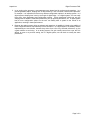
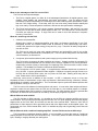
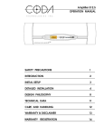
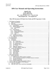
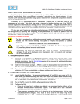
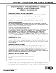
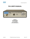
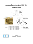
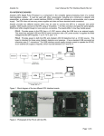
Amptek Inc.
Digital Processor FAQ
What are the DP4, PX4, and X123? How are they different?
All three are portions of the complete signal processing electronics in a nuclear instrumentation system.
All three are based upon the same core technology, digital pulse processing. All three replace many
different components in a traditional instrumentation system: the shaping amplifier, the multichannel
analyzer, logic devices, and several auxiliary components.
The first difference is that the DP4 represents only the core of the pulse processing electronics, the
shaping amplifier and multichannel analyzer. The PX4 includes this same core but also includes low and
high voltage power supplies. The X123 inclues all of this, but also includes the detector and preamplifier.
The second difference is that the PX4 is a packaged instrument, suitable for standalone benchtop use,
with a great deal of flexibility and configurability via its serial interface. It is intended for laboratory use where
one can tailor its configuration for specific measurments and applications. It can be used with many
detectors and preamps, including most commercially available units. The X123 is a complete packaged
system, with the detector integrated onboard. It is very small, compact and easy to operate but has less
flexibility and configurability than the PX4. The DP4 is a single board and so requires effort to mount and
package it, to provide power supplies, and so on and does not offer all of the features of the PX4.
So the three systems differ in (1) how much of the complete system is included, (2) their packaging,
which greatly affects their ease of use, and also (3) the flexibility and ease of use. The PX4 is strongly
recommended for the laboratory user: it has great flexibility, convenient packaging, and in many applications
provides the best performance. The X123 is is the most compact, package system and is recommended for
OEMs needing a packaged box or for users requiring a very compact system. The DP4 is recommended for
OEMs who want to integrate board level solution inside their packaged system.
How are the DP4, PX4, and X123 used in an instrumentation system?
Figure 1 shows the block diagram of a traditional analog nuclear instrument. It includes the detector,
preamplifier, shaping amplifer, MCA, and computer (with serial interface), along with the power supplies and
(often) various auxiliary functions or modules. Figure 2 shows the block diagram of an instrument based on
digital pulse processing. It includes the same basic elements and implements the same functions. The main
difference is that the analog to digital conversion occurs closer to the front of the signal processing chain,
immediately after the preamplifier rather than after the shaping amplifier. The input to the digital processing
core is the preamplifier output. This is digitized, then real-time digital processing is applied to the signal, the
peak amplitude is detected (digitally), and this value is binned in histogramming memory, generating an
energy spectrum. The spectrum is then transmitted over a serial interface to the user’s computer. The
inputs and outputs are the same as in a traditional system: the input is the preamp signal, while the output is
a spectrum (or histogram) sent over a serial interface. The same basic signal processing occurs, but the use
of digital technology offers several key performance advantages.
Preamplifier
Detector
Differentiator
Gain
Integrator
Baseline
Restorer
Peak
Detect &
ADC
Fast
Shaping
Pile-Up
Reject
Gate Logic
Histogram
Memory
Computer
Shaping Amplifier
High Voltage
Power Supply
Preamp Power
Supply
Peltier Cooler
Supply
Power Supplies
Multichannel Analyzer
Single
Channel
Analyzers
Risetime
Detection
Auxilary Logic
Figure 1. Bock diagram of a traditional analog spectroscopy system. In addition to the detector and
preamplifier, it includes a shaping amplifier, an MCA, power supplies, and auxiliary logic function. These are
generally separate modules.
Page 1 of 8
Amptek Inc.
Detector
Digital Processor FAQ
Preamplifier
Analog
Prefilter
DP4
ADC
Digital Pulse
Shaper
Pulse
Selection
Logic
Thermoelectric
Cooler Supply
X123
Histogram
Logic
Microcontroller
Serial
Interface
Computer
Aux
Outputs
High
Voltage
Suply
Low
Voltage
Supplies
+5V DC
PX4
Figure 2. Block diagram of the PX4. It includes the same functions as a traditional system, but in a single,
compact module. Digital processing permits greater flexibility in the configurations and makes changing
configurations easier.
Figure 2 also illustrates a primary difference between the three systems: the DP4 contains the core
signal processing circuitry (shaping amplifier and MCA), the PX4 contains this same core and also the power
supplies, while the X123 contains the same functionality as the PX4 plus an integrated detector and
preamplfier.
What is “digital pulse processing” and how does it differ from analog processing?
The output from the preamplifier (a charge sensitive preamplifier) is a small, fast voltage step. With
Amptek’s XR100, the gain is 1 mV/keV, so for X-rays the preamp output signal is tens of mV. The goal is to
measure this with a resolution of a couple hundred eV, or <0.2 mV. The signal has a risetime of 100 nsec or
so and a decay time of milliseconds or more. This signal is superimposed on a variable DC baseline and
has considerable white noise due to thermal noise in the preamplifier, shot noise in the detector, etc. The
signals occur at random time intervals, often at tens of thousands of events per second.
In both analog and digital pulse processing systems, this preamplifier output goes to a shaping amplifier
and then to a multichannel analyzer (MCA). The shaping amplifier’s purpose is to permit an accurate
determination of the peak height. The pulse shaping removes the DC baseline, reduces distortions due to
overlapping pulses, and filters out the broadband noise. The shaping amplifier also amplifies the pulse to
permit accurate measurements. Both digital and analog systems have this same purpose and include similar
elements: a differentiator (or high pass filter), an integrator (or low pass filter), voltage gain, baseline
restoration, etc. In both systems, the pulse amplitude is ultimately obtained in a digital form, yielding an
energy spectrum in the MCA memory.
The difference is that the analog processor uses analog circuitry to perform the pulse shaping, then
digitizes the peak of the final shaped pulse. The pulse shaping is implemented using op-amps, resistors,
and capacitors. The digital processor digitizes the preamplifier output, then shapes the pulse with a digital
filter running in an FPGA. The functions are the same, but the digital pulse processor moves the digitization
earlier in the signal processing chain.
What are the advantages of digital pulse processing?
There are three primary advantages: better performance, greater flexibility, and greater stability and
reproducibility.
1. Researchers derived long ago the ideal filters for use in nuclear electronics, e.g for the best signalto-noise ratio at a given count rate. The transfer function cannot easily be produced in practical opamp circuits. But digital processors have fewer restrictions and so can more closely approximate the
ideal transfer functions. This improves performance.
2. There is no dead time associated with the peak detect and digitization, so a digital processor has
considerably higher throughput than an analog system. Further, since it has a finite impulse
response, pile-up and other pulse overlap effects are reduced. The digital processor’s performance
is particularly good at high count rates.
Page 2 of 8
Amptek Inc.
Digital Processor FAQ
3. In an analog pulse processor, most parameters are determined by resistors and capacitors. In a
pseudo-gaussian shaper, shaping time is determined by a set of fourteen resistors and capacitors,
for example. It is impractical to have many different configuration options in an analog system. In a
digital system, shaping time is set by the length of digital delay. In a digital system, one can easily
have many more parameters and configuration options. These parameters include not only the
shaping time but baseline restoration parameters, pile-up rejection parameters, etc. A digital system
has far more configuration options so the user can readily tailor a system to the needs of an
application, resulting in better performance.
4. Because the analog system relies on resistors and capacitors, its stability is limited to the stability of
these components and its reproducibility to their tolerances. In a digital system, the stability and the
reproducibility are much better, because they derive from a few very accurate references, eg. the
crystal oscillator to set timing. In an analog system, fine gain usually comes from a pot and it is
difficult to return to a previous setting, but in a digital system, one can back to exactly the same
parameters.
Page 3 of 8
Amptek Inc.
Digital Processor FAQ
What are the advantages of the PX4 over the PX2?
The PX4 has two major advantages.
1. The PX4 is a digital system, so offers all of the advantages listed above for digital systems: more
flexibility, better stability and reproducibility, and better performance. One can adjust the PX4
parameters to optimize separately for low and high count rates, obtaining better performance in each
than the PX2’s single setting. It has lower noise (for low count rates), better baseline stability 9at
high count rates), a lower temperature coefficient, and various other performance advantages.
2. The PX4 is more convenient. It is a single, compact, light-weight package. With the PX2, you need
not only the PX2 but also the MCA, power cables for each, etc. The PX2 requires 110VAC while the
PX4 does not need line voltage. A single PX4 can be used for all of the detectors in Amptek’s
inventory, Si and CdTe.
What do I need along with the PX4?
1. A detector and preamplifier.
Amptek has a series of detector/preamplifier units which are designed specifically for the PX4.
Designated XR100s, this includes Peltier-cooled Si detectors for X-ray spectroscopy and Peltiercooled CdTe detectors for higher energy X-rays and for γ-rays. These are all easily configured for
use with the PX4.
The PX4 can be used with most other standard detectors and preamplifiers used in the nuclear
industry – other solid state detectors, scintillators, etc. The PX4 can be configured for use with these
various detectors, as discussed in
2. A computer (with interface software) and a power supply (one is provided with the unit).
The PX4 requires a computer for data acquisition and control. Amptek provides the necessary PC
software (it can be downloaded from our website, free of charge), suitable for PCs running Windows.
Amptek also provides a library of subroutines for interfacing to the PX4 from within a user’s custom
software. The standard PX4 includes a USB and an RS232 interface.
The PX4 requires a 5V DC power supply. It is supplied with a standard transformer to produce 5V
from 120 VAC. It can be operated from other supplies. USB does not specify enough current to run
the PX4 with an XR100 Peltier cooler, but can power the PX4 itself. Battery packs may also be
used. Please refer to XX for specifications.
Obviously, some source of radiation is also required. In XRF, a radioactive source or X-ray tube
stimulates emission of characteristic X-rays, which are detected. Mechanical fixturing, collimators, shutters,
and shielding are needed in most applications. The PX4 includes inputs to synchronize data acquisition with
opening shutters, turning on the tube, etc.
The PX4 comes with software for data acquisition and control. In most cases, data analysis software is
required to reduce the raw spectra from the PX4 into the final data, e.g. the material present in a sample.
Amptek has software which can be used for X-ray fluorescence. For other analyses, the PX4’s spectral data
are stored in an ASCII file format which can be read by most analysis programs or by Excel.
Will the PX4 work with an MCA?
The PX4 includes an MCA internally. It is possible to use the PX4 as a shaping amplifier only but not
recommended. One can send the preamp signal to the PX4, use it for pulse shaping, then send this (digital)
shaped pulse to the PX4’s DAC, and connect this with the user’s external MCA. However, some loss of
performance is often observed, due to grounding issues and to the digital nature of this shaped output. We
recommend use of the PX4’s internal MCA, since it is available anyway and will generally provide the best
performance.
Will the PX4 work with a traditional shaping amplifier? Can the PX4 be used as an MCA only?
The PX4 replaces a traditional shaping amplifier. It is not possible to connect the output of a traditional
shaping amplifier to the PX4 and use it as an MCA only. The circuitry before the ADC will further shape the
input, resulting in a highly distorted (not useful) pulse.
Page 4 of 8
Amptek Inc.
Digital Processor FAQ
Will the PX4 work with Amptek’s XR100 detectors?
Yes. It was optimized for use with them.
configuration files for each.
It will work with all of Amptek detectors and includes
Will the PX4 work with all detectors and preamplifiers?
It will certainly work with most standard detectors and preamplifiers. We hesitate to say “all” because
such a wide variety is in use.
What software do I use with the PX4?
Amptek provides a software package, ADMCA, which provides data acquisition and control for all of
Amptek’s standard nuclear components with serial interface, including the MCA8000A, the DP4, the PX4, the
X123, and the GammaRad. This is suitable for configuring the PX4 and acquiring and saving data. It saves
data in a standard ASCII format which can be read by most spectrum analysis software packages. It can
also be ready by Excel. For X-ray fluorescence analysis, Amptek has available the XRF-FP software
package. For other applications, there are software packages available from various vendors.
Amptek also provides a library of subroutines for interfacing with the PX4, DP4, etc. With this library, a
user can control the hardware within his or her own software package and interface.
Will the PX4 work with a McIntosh computer? Will the PX4 work with a computer running LINUX?
Amptek’s standard software, the ADMCA package and the DLL library, are compiled for WindowsTM
only. However, some Amptek customers have written their own software to run under LINUX or on a
McIntosh and may be willing to provide this collaboratively. Please contact Amptek for details.
How do I configure the PX4 for an Amptek XR100 detector?
The PX4 software, ADMCA, includes a library of default configuration files for Amptek’s detector. These
represent generic configurations which provide decent performance for most customers. For the optimum
performance in any specific application, the configuration parameters can be tweaked.
Page 5 of 8
Amptek Inc.
Digital Processor FAQ
What do I need along with an X123?
Only two items: a source of radiation and a personal computer to control the instrument and acquire the
data. The X123 includes everything else: detector, preamplifier, digital pulse shaping electronics,
multichannel analyzer, serial interface, and power supplies. A +5V AC-DC adapter is included for power.
The software which runs on the PC to contrl the X123 is also included. The X123 is a packaged solution, so
all one need do is open the box, make the connections, install the software, and begin acquisition.
What do I need along with a DP4?
The DP4 is only a portion of the complete system and is an unpackaged board. The following items are
required to make measurements:
1)
Radiation source
2)
Detector and preamplifier. Amptek’s XR100 series may be used, but detectors and preamplifiers from
other vendors may also be used.
3)
Power supplies. Amptek’s PC4-2 may be used to power only the DP4, or the PC4-3 may be used to
power the DP4 and XR100.
4)
Packaging and interconnects. The DP4, PC4-2, and PC4-3 are bare boards. They need to be mounted
in a box or package of some sort. Connectors must added. Some assembly effort is certainly required
to use them.
5)
Personal computer. A PC is needed to run the software.
Page 6 of 8
Amptek Inc.
Digital Processor FAQ
What is the difference between “peaking time” and “shaping time”?
This is the source of much confusion, in both analog and digital pulse processing. The simple answer is
that the PX4 with peaking time TP will have performance similar to that of an analog shaper with shaping time
constant τ, where 2.2τ=TP.
For the longer answer, we must recognize that τ is related to the time constant of the low pass filter
stages and so is also related to the peaking time of the output pulse, to the pulse duration, and to the noise
bandwidth (in the frequency domain). The relationship between these quantities depends on the details of
the transfer function of the filter which does the pulse shaping. Shown below is an oscilloscope trace of a
quasi-triangular shaped pulse from an analog pulse shaper, an Amptek PX2, with τ = 20 μsec (the horizontal
axis is 20 μsec/div). This is considered the shaping time it is the real component of the poles of the transfer
function. The risetime is 44 μsec, or 2.2τ. The pulse is slightly asymmetric, with a settling time slightly
longer than its rise time. The FWHM is about 50 μsec.
44 μsec
50 μsec
An oscilloscope trace of a PX4 shaped pulse is shown below (20 μsec/div). The risetime is well defined at
51 μsec. The pulse is triangular, so is symmetric and has duration 51 μsec (FWHM). The noise bandwidth
is comparable to that of a quasi-triangular shaper with the same risetime, so 23 μsec. It will have pile-up
properties similar to those of the PX2 output above, but slightly larger noise bandwidth and therefore lower
noise.
Prefilter Output
(ADC Input)
PX4 Output
Page 7 of 8
Amptek Inc.
Digital Processor FAQ
What is the difference between the “fast channel” and the “slow channel”?
What is the difference between the “fast threshold” and the “slow threshold”?
What is the difference between the “counts” and the “incoming counts”?
The “fast” and “slow” channels are two parallel signal processing paths inside the PX4, operating at
different shaping times. They are optimized to obtain different data about the incoming pulse train. The
“slow” channel, which has a long shaping time constant, is optimized to minimize electronic noise, to obtain
an accurate pulse height. The “fast” channel, which has a short shaping time constant, is optimized to detect
pulses which are closely spaced in time and so overlap (or pile up) in the slow channel.
Peak Detect
Preamplifier
Detector
Spectrum
Slow Channel
(Long Shaping Time)
Analog
Prefilter &
ADC
Slow Threshold
Fast Channel
(Short Shaping Time)
Pile-Up
Detect
Fast Threshold
Incoming
Counts
For most detectors, electronic noise is minimized at a fairly long shaping time constant. For Amptek’s
XR100 Si detectors, minimum noise is found with a peaking time of 20 to 50 μsec. So the slow channel is
operated at this long time constant, and its output is connected to the peak detect circuit and used to obtain
the energy spectrum.
Since radiation interacts in the detector at random intervals, it is possible to have two interactions occur
within the processing time of the slow channel. Even at low count rates this will occur occasionally and in
most applications, it is useful to operate at a high count rate to minimize data acquisition time. Two problems
occur when the pulses overlap in time: only a single pulse is recorded rather than two, and the detected peak
has an incorrect amplitude. To address this, there is a fast channel with a peaking time of 0.4 μsec. Pulses
which overlap in the slow channel but not in this fast channel may be rejected from the spectrum, to minimize
the distortions. If pile-up reject (PUR) is turned on, then they are rejected. Further, the fast channel is used
to measure the true incoming count rate (ICR), where far fewer pulses are rejected. Additional information
on pulse pile-up can be found in the PX4 User Manual.
Note that separate thresholds are used in the fast and slow channels. Since the fast channel is usually
operated further from the noise corner, it has a much higher noise level and so the threshold must be higher.
The “counts” in recorded by the PX4 are those in the spectrum, those detected in the slow channel. The
“incoming counts” recorded by the PX4 are those detected in the fast channel, where the dead time is much
less.
Page 8 of 8