1
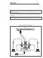
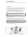
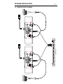
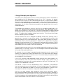
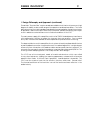
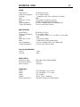
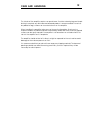
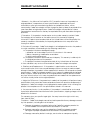
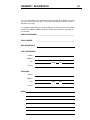
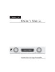
Amplifier S12.5
OPERATION MANUAL
T
E
C
H
N
O
L
O
G
I
E
S
I
N
C
.
XLR/GN
BIAS
PRECISION BIAS CLASS A AMPLIFIER
S
INPUT
LEFT
RIGHT
RCA/YL
12.5
SAFETY PRECAUTIONS
1
INTRODUCTION
2
INITIAL SETUP
3
DETAILED INSTALLATION
4
DESIGN PHILOSOPHY
8
TECHNICAL DATA
11
CARE AND HANDLING
12
WARRANTY & DISCLAIMER
13
WARRANTY REGISTRATION
14
SAFETY PRECAUTIONS
1
CAUTION
WARNING
!
CAUTION: TO PREVENT ELECTRIC SHOCK,
DO NOT REMOVE COVER. NO USER
SERVICEABLE PARTS INSIDE, REFER
SERVICING TO QUALIFIED SERVICE
PERSONNEL.
THIS SYMBOL IS TO ALERT YOU OF THE
PRESENCE OF UNINSULATED DANGEROUS VOLTAGE WITHIN THE UNIT'S
ENCLOSURE THAT MAY BE OF SUFFICIENT MAGNITUDE TO CONSTITUTE A
RISK OF ELECTRIC SHOCK.
!
THIS SYMBOL IS INTENDED TO ALERT
YOU OF THE PRESENCE OF IMPORTANT
OPERATING AND MAINTENANCE
INSTRUCTIONS IN THE LITERATURE
ACCOMPANYING THE UNIT.
WARNING: TO PREVENT FIRE OR SHOCK HAZARD, DO NOT
EXPOSE THIS UNIT TO RAIN OR MOISTURE. TO
AVOID ELECTRICAL SHOCK, DO NOT OPEN THE
UNIT. REFER SERVICING TO QUALIFIED PERSONNEL.
CAUTION -
Never install or remove the power cord from the chassis
unless it has been disconnected from the AC power source
first.
Never pull on the power cord when removing it from an AC
power source. Grasp it by the plug.
Do not leave the power cord connected to an AC power
source unless it is connected to the unit.
It is recommended that during extended periods of nonuse
the unit's power cord be unplugged from its AC power
source.
Route the AC power cord so that it will not be damaged or
walked on.
INTRODUCTION
2
Thank you for purchasing the AMPLIFIER S12.5.
This amplifier is a precision device, designed in an effort to provide
the listener with unmatched sound quality through superb design
and construction.
Although its operation is fairly simple, in order to operate your
amplifier properly and to realize all of the capabilites of the S12.5 we
recommend that you read this entire manual carefully.
INITIAL SETUP
3
WARNING: Please ensure that the power switch is turned OFF while you are connecting the
amplifier. Connecting or disconnecting cables while the amplifier is powered on could cause
damage to your speakers.
The diagram below shows the default connections necessary to operate the AMPLIFIER S5.5 as a
stereo amplifier. This is the simplest and most common mode of operation, and the quickest way
to get started.
Note: Ensure that the MODE switch located between the input jacks on the rear of the amplifier is
set to the STEREO position for normal operation. Bridged operation is explained on page 7.
Stereo Amplifier Configuration
PREAMPLIFIER
!
~
AC LINE INPUT
SEE SERIAL T AG FOR
POWER REQUIREMENTS
FOR CONTINUED PROTECTION AGAINST
SHOCK OR FIRE HAZARD,DO NOT EXPOSE
THIS UNIT TO RAIN OR MOISTURE.
VIDEO
UNBALANCED OUTPUT
LEFT
RIGHT
LEFT
PROCESSOR
LEFT
IN
RIGHT
LEFT
RIGHT
LEFT CHANNEL
OUT
MONITOR
IN
RIGHT
LEFT
RIGHT
OUT
LEFT
INPUTS
VIDEO
INPUTS
UNBALANCED
LEFT
RIGHT
TUNER
RIGHT
LEFT
RIGHT
COMPACT DISC
LEFT
RIGHT
UNBALANCED INPUT
LEFT
RIGHT
RIGHT CHANNEL
UNBALANCED
PUSH
PUSH
BALANCED
BALANCED
MODE
STEREO
BRIDGED
FOR CONTINUED PROTECTION
CAUTION
AGAINST SHOCK OR FIRE:
MODEL
1. REPLACE FUSE WITH SAME
SERIAL NUMBER
TYPE AND RATING
VOLTAGE REQUIREMENT
HZ
POWER REQUIREMENT
VA
2. DO NOT EXPOSE THIS UNIT
T
E
C
H
N
O
L
O
G
I
E
S
I
N
C
.
!
AC LINE FUSE CHART
VOLTAGE
100V
WARNING
MANUFACTURED IN THE USA
TO RAIN OR MOISTURE
~
AC LINE INPUT
NOTE
MAIN POWER
FUSE AND VOLTAGE SELECTOR
FUSE TYPE
!
TO PREVENT ELECTRIC SHOCK, DO NOT
REMOVE COVER. NO USER SERVICEABLE
PARTS INSIDE. REFER SERVICING TO
QUALIFIED SERVICE PERSONNEL.
!
DO NOT ALLOW AMPLIFIER OUTPUTS
TO COMMON BETWEEN CHANNELS,
12 AMP
SLOW BLOW 5 x 20mm
OR CONTACT CHASSIS OR INPUT
120V
12
0
GROUNDS, OR TO BE CONNECTED
220V
TO ANY ACTIVE CURRENT SOURCE.
6 AMP
SLOW BLOW 5 x 20mm
240V
SEE SERIAL TAG FOR POWER
REQUIREMENTS, REMOVE POWER
CORD BEFORE CHANGING
FUSE OR LINE VOLTAGE
LEFT SPEAKER
FUSE VALUE -SEE FUSE CHART
VOLTAGE SELECTIONSEE OPERATION MANUAL
OFF
ON
AMPLIFIER S12.5
RIGHT SPEAKER
DETAILED INSTALLATION
4
I. Connections
The connectors and controls are clearly marked on the back panel of the AMPLIFIER.
Note the correct left or right channel orientation. The function and channel markings on
the rear panel correspond to the front panel controls and their signal paths.
1.The UNBALANCED and BALANCED inputs should be attached to the
appropriate unbalanced and balanced outputs of a preamplfier either directly
or through a crossover or processor, as appropriate to the application.
2.The LEFT OUTPUT and RIGHT OUTPUT should be attached to the left and right
speakers.
WARNING: There are no fuses on the amplifier’s outputs in order to cut down on
output impedance effects. Speaker protection is left to the manufacturer of your
speakers, as they would best know how to protect their product.
3.The AC LINE INPUT should be connected to an AC outlet with the power cable
provided with the amplifier.
4.The FUSE AND VOLTAGE SELECTOR unit houses a 5x20mm slow-blow fuse and a
voltage selector cartridge. Ensure that the voltage, visible through a small window
next to the AC input, is set to the appropriate voltage for your country. When
changing voltages, ensure that the power cable is disconnected from the amplifier.
Note: If the fuse in your amplifier blows, contact a Coda dealer or call Coda
directly before attempting to use the amplifier again.
3.The POWER SWITCH can usually be left on when the amplifier is functioning
correctly. With the bias disabled the amplifier will draw negligible current and can
thus be left in “standby” indefinitely.
2
1
LEFT CHANNEL
2
INPUTS
RIGHT CHANNEL
INPUTS
UNBALANCED
UNBALANCED
PUSH
PUSH
BALANCED
BALANCED
MODE
STEREO
BRIDGED
FOR CONTINUED PROTECTION
CAUTION
AGAINST SHOCK OR FIRE:
MODEL
1. REPLACE FUSE WITH SAME
SERIAL NUMBER
TYPE AND RATING
VOLTAGE REQUIREMENT
HZ
POWER REQUIREMENT
VA
2. DO NOT EXPOSE THIS UNIT
T
E
C
H
N
O
L
O
G
I
E
S
I
N
C
.
MANUFACTURED IN THE USA
TO RAIN OR MOISTURE
!
AC LINE FUSE CHART
VOLTAGE
100V
WARNING
~
AC LINE INPUT
NOTE
MAIN POWER
FUSE AND VOLTAGE SELECTOR
FUSE TYPE
!
TO PREVENT ELECTRIC SHOCK, DO NOT
REMOVE COVER. NO USER SERVICEABLE
PARTS INSIDE. REFER SERVICING TO
QUALIFIED SERVICE PERSONNEL.
!
DO NOT ALLOW AMPLIFIER OUTPUTS
TO COMMON BETWEEN CHANNELS,
12 AMP
SLOW BLOW 5 x 20mm
6 AMP
SLOW BLOW 5 x 20mm
OR CONTACT CHASSIS OR INPUT
120V
12
0
GROUNDS, OR TO BE CONNECTED
220V
TO ANY ACTIVE CURRENT SOURCE.
240V
SEE SERIAL TAG FOR POWER
REQUIREMENTS, REMOVE POWER
CORD BEFORE CHANGING
FUSE OR LINE VOLTAGE
3
FUSE VALUE -SEE FUSE CHART
VOLTAGE SELECTIONSEE OPERATION MANUAL
4
OFF
ON
5
DETAILED INSTALLATION
5
II. Front Panel Control Functions and Indicators
1. The BIAS button enables the bias, effectively "turning on" the amplifier's
components, and opens shunting relays that mute the input.
2. The INPUT SELECTOR button switches between the balanced and unbalanced
inputs.
3. These LEDs, when lit, indicate that the bias is enabled and muting is off.
4. This two color LED indicates that the main power is on. When it is red the
balanced inputs are in use. When it is yellow the unbalanced inputs are in use.
XLR/GN
BIAS
PRECISION BIAS CLASS A AMPLIFIER
S
INPUT
RIGHT
LEFT
RCA/YL
12.5
1 2
3
4
Note: If a power interruption occurs to the system the amplifier will power on with the
bias off. Press the BIAS button to resume use of the amplifier.
DETAILED INSTALLATION
6
III. BRIDGED SETUP
WARNING: Disconnect the amplifier's power cord from the AC supply and set the power switch
to OFF before adjusting the mode switch or connecting or disconnecting any cables
to avoid potential damage to your speakers.
The S12.5 normally operates in stereo mode, providing a maximum output power of
50 watts Class A (into an 8-ohm load) per channel. In BRIDGED mode, both channels
act as one amplifier providing a maximum output power of 200 watts. For extremely
high-power multi-channel audio applications, multiple S12.5 amplifiers can be used
in place of one medium-power stereo amp.
To configure the amplifier for bridged mode operation, set the mode switch on the
back panel to the BRIDGED setting as shown in the diagram below.
Back of AMPLIFIER S12.5
PUSH
PUSH
MODE
STEREO
BRIDGED
MODEL
SERIAL NUMBER
In bridged mode only one audio input is used. No other input should be connected,
and the bridged mode input must be a BALANCED signal connected to the XLR
receptacle labeled BRIDGED INPUT. Bridged mode will not operate correctly with an
input adapted from an unbalanced signal. Connecting the input signal to the
receptacle not labeled BRIDGED INPUT will cause no damage, but will cause the
speaker terminal polarities to reverse, so should be avoided in the interest of
consistency in labeling.
The amplifier’s speaker terminals are reconfigured in bridged mode. The left channel
positive terminal becomes the bridged negative terminal and the right channel
positive terminal becomes the bridged positive terminal.
See the next page for a diagram of a stereo amplifier configuration using two
bridged mode S12.5 amplifiers. Speaker terminals in the diagram are marked with
their bridged mode polarities.
Technical Note: In bridged mode the XLR input receptacles are internally connected to each other
according to the diagram below.
Bridged Mode XLR Wiring
PUSH
1
PUSH
2
3
1
2
3
7
DETAILED INSTALLATION
IV. BRIDGED SETUP DIAGRAM
LEFT SPEAKER
Bridged
Output
LEFT CHANNEL
INPUTS
I
UNBALANCED
G
BALANCED
O
E
S
I
N
C
PUSH
.
STEREO
MODE
BRIDGED
PUSH
FUSE AND VOLTAGE SELECTOR
12
0
FUSE VALUE -SEE FUSE CHART
VOLTAGE SELECTIONSEE OPERATION MANUAL
OFF
MANUFACTURED IN THE USA
INPUTS
BALANCED
UNBALANCED
CAUTION
WARNING
!
!
TO ANY ACTIVE CURRENT SOURCE.
GROUNDS, OR TO BE CONNECTED
OR CONTACT CHASSIS OR INPUT
TO COMMON BETWEEN CHANNELS,
DO NOT ALLOW AMPLIFIER OUTPUTS
NOTE
TO PREVENT ELECTRIC SHOCK, DO NOT
REMOVE COVER. NO USER SERVICEABLE
PARTS INSIDE. REFER SERVICING TO
QUALIFIED SERVICE PERSONNEL.
RIGHT CHANNEL
MODEL
FOR CONTINUED PROTECTION
L
AGAINST SHOCK OR FIRE:
O
HZ
N
VOLTAGE REQUIREMENT
H
SERIAL NUMBER
C
1. REPLACE FUSE WITH SAME
E
MAIN POWER
TYPE AND RATING
T
AC LINE INPUT
SEE SERIAL TAG FOR POWER
REQUIREMENTS, REMOVE POWER
CORD BEFORE CHANGING
FUSE OR LINE VOLTAGE
~
VA
FUSE TYPE
SLOW BLOW 5 x 20mm
SLOW BLOW 5 x 20mm
ON
POWER REQUIREMENT
2. DO NOT EXPOSE THIS UNIT
6 AMP
12 AMP
AC LINE FUSE CHART
TO RAIN OR MOISTURE
!
VOLTAGE
120V
100V
220V
240V
Bridged
Output
!
~
AC LINE INPUT
SEE SERIAL T AG FOR
POWER REQUIREMENTS
FOR CONTINUED PROTECTION AGAINST
SHOCK OR FIRE HAZARD,DO NOT EXPOSE
THIS UNIT TO RAIN OR MOISTURE.
UNBALANCED OUTPUT
LEFT
RIGHT
LEFT
VIDEO
RIGHT
LEFT
IN
RIGHT
PROCESSOR
LEFT
OUT
RIGHT
LEFT
IN
RIGHT
LEFT
OUT
RIGHT
LEFT
VIDEO
RIGHT
LEFT CHANNEL
LEFT
E
S
TUNER
INPUTS
G
I
UNBALANCED
O
BALANCED
L
I
C
RIGHT
N
PUSH
.
COMPACT DISC
LEFT
RIGHT
STEREO
MODE
BRIDGED
PUSH
FUSE AND VOLTAGE SELECTOR
12
0
FUSE VALUE -SEE FUSE CHART
VOLTAGE SELECTIONSEE OPERATION MANUAL
OFF
MANUFACTURED IN THE USA
CAUTION
WARNING
!
!
TO ANY ACTIVE CURRENT SOURCE.
GROUNDS, OR TO BE CONNECTED
OR CONTACT CHASSIS OR INPUT
TO COMMON BETWEEN CHANNELS,
DO NOT ALLOW AMPLIFIER OUTPUTS
NOTE
TO PREVENT ELECTRIC SHOCK, DO NOT
REMOVE COVER. NO USER SERVICEABLE
PARTS INSIDE. REFER SERVICING TO
QUALIFIED SERVICE PERSONNEL.
RIGHT CHANNEL
UNBALANCED INPUT
LEFT
RIGHT
INPUTS
BALANCED
UNBALANCED
MODEL
O
AGAINST SHOCK OR FIRE:
FOR CONTINUED PROTECTION
MONITOR
PREAMPLIFIER
Bridged
Output
N
HZ
H
VOLTAGE REQUIREMENT
C
SERIAL NUMBER
E
MAIN POWER
1. REPLACE FUSE WITH SAME
T
AC LINE INPUT
TYPE AND RATING
SLOW BLOW 5 x 20mm
SEE SERIAL TAG FOR POWER
REQUIREMENTS, REMOVE POWER
CORD BEFORE CHANGING
FUSE OR LINE VOLTAGE
~
VA
12 AMP
SLOW BLOW 5 x 20mm
ON
POWER REQUIREMENT
2. DO NOT EXPOSE THIS UNIT
6 AMP
FUSE TYPE
AC LINE FUSE CHART
TO RAIN OR MOISTURE
!
VOLTAGE
120V
100V
220V
240V
Bridged
Output
RIGHT SPEAKER
DESIGN PHILOSOPHY
8
I. Design Philosophy and Approach
The subtlety of the design process at this level of performance makes it impossible to
easily explain all of the advantages inherent in the S12.5. However, we present
here an overview to give you an understanding of some of its unique features and an
idea of the listening experience you can expect. Often a particular technique has
numerous unrelated advantages and possibilities. We make every effort to exploit these
advantages with the final result being an amplifier that is greater than the sum of its
individual features
The topology and component selection is built on the foundation established by the
System 100. Balanced interconnections are provided to take advantage of their
greater noise rejection as in the System 100. Differential voltage gain throughout provides
exceptional rejection of external noise and contributes to the inherent DC stability of the
circuit. This allows direct coupling without servo circuitry. The unit also uses output
followers operating without feedback.
The front end of the S12.5 is designed to operate without ever entering Class B
operation as is common in many other designs. This combined with excellent high
frequency design insures linear operation at high speed, and translates into a sonic
reproduction which is extremely transparent in character. The supplie take a very direct
approach to high performance. First, a top quality toroid transformer and over 144,000
uf of capacitance with very low ESR and inductance is used. For optimum performance
and reliability all circuity remains continuosly powered.
The specifications are consistent with what would be expected in a high current Class A
amplifier design. In this design , however , an unusual degree of attention has been paid
to sonically meaningful parameters.
For example, the current stage is capable of producing peak currents in excess of 100
Amperes with a degree of linearity and speed which is not matched by other designs
when producing only a fraction of of this current. This is achieved by the implementation
of several distinct circuit features.
In the S12.5 extremely wide bandwidth output transistors are used instead of the
usual TO3 devices which are used in other transistor designs. Each channel uses 30
individual output transistors with a combined power rating of 1500 Watts and 120
Amperes with a bandwidth of 50 Mhz.
The manner in which the S12.5 accomplishes Class A operation is also different
than that employed in conventional designs. All Class A designs leave Class A operation
when they are operated into loads of sufficiently low impedance or power levels.
Generally, this transition will produce a large and abrupt distortion increase.
The S12.5 uses bias voltages and component values which have been specifically selected to produce a precision transition with no abrupt changes in distortion or
output impedance. This“Precision Bias” technique yields seemless performance regardless of the complexity of the load impedance and is particularly effective at eliminating
a form of IM distortion which often occurs in these instances.
DESIGN PHILOSOPHY
9
I. Design Philosophy and Approach (continued)
To maintain “Precision Bias” requires an advanced bias circuit that must have a very high
degree of stability under a wide range of temperatures and load conditions. The usual
bias network is of such high impedance and poor thermal regulation that at the extremes
of operation, bias currents are ineffectively controlled. Advanced tracking techniques
results in absolute control of bias currents under all conditions in the S12.5.
The main power supply of the amplifier consists of a 1500VA toroidal power transformer
with independent rectifiers to isolate the channels from one another. One hundred
fourty-four thousand microfarads of total capacitance provide effective filtering.
The above attributes result in a amplifier of such extreme linearity and bandwidth that no
overall feedback correction is required or used. One advantage of this is a high degree
of immunity from interactions with loads or cables and a superior transient response. An
extremely low nonreactive output impedance is maintained well beyond 20,000 hz. The
resulting uniform damping factor is not usually found in other designs.
The S12.5 has all structural parts made of machined aluminum which are milled
to very close tolerances yielding the seamless appearance characteristic of previous
products from Coda. As with all Class A amplifiers, heat dissipation is important. The
S12.5 uses four massive heat sinks for efficient, noiseless, and clean thermal relief.
The thermal coefficient of the heat sinks is one of the lowest and most effective in the
audio industry.
DESIGN PHILOSOPHY
10
II. Material Quality
The amplifier’s chassis is made from heavy-gauge steel with a half-inch machined
aluminum faceplate. All exterior metal parts are anodized or powder coated for
durability.
Printed circuit boards are fiberglass epoxy with gold plating over a tin/nickel barrier.
The gold layer will not corrode, while the barrier layer prevents the gold from migrating
to the lower copper layer.
All resistors are precision metal film; 1% tolerance for 1/4-watt and 5% tolerance for
1-watt.
Capacitors have been eliminated wherever possible. No electrolytic capacitors are
used except in the power supply, where several high-capacitance electrolytics
provide outstanding filtering of the supply output.
All semiconductor devices are of very high grade. Voltage gain is accomplished with
an extremely high-quality, matched dual FET, chosen for it’s exceptionally low noise
characteristics.
All audio input and output connector contacts are gold-plated, and XLR receptacles
are manufactured by Neutrik of Switzerland. Wire is used as little as possible in the
signal path - only to connect the RCA jacks and speaker terminals to the circuit board
- and what is used is 141-strand silver-plated copper with silicone insulation.
11
TECHNICAL DATA
STEREO
Rated Power:
Frequency Response:
Distortion:
Gain:
Maximum Current:
Noise:
input Impedance:
Output Impedance:
125 Watts @ 8 Ohms
DC to -3dB @ 100kHz
< .03 percent from 10Hz to 20kHz @ 125 Watts
26dB
>100 Amperes peak per channel
-120dB referenced to rated output
50k Ohms unbalanced/1k Ohms balanced
.03 Ohms from 20Hz to 20kHz
BRIDGED MONO
Rated Power:
Frequency Response:
Distortion:
Gain:
Maximum Current:
Noise:
Input Impedance:
Output Impedance:
500 Watts @ 8 Ohms
DC to -3dB @ 100kHz
< .03 percent from 10 Hz to 20kHz @ 400 Watts
32dB
>100 Amperes peak
-120dB referenced to rated output
1k Ohms unbalanced/1k Ohms balanced
.06 Ohms from 20Hz to 20kHz
CLASS A/AB OPERATION
Class A:
Class AB:
< 20W
>20W
POWER SUPPLY
Transformer Type:
Transformer Rating:
Power Filtering:
Multi-tap, multi-winding toroidal
1500 VA
144,000 µF
DIMENSIONS
Height:
Width:
Depth:
Weight:
Power requirement:
5.25" Faceplate, 6.0" Overall
19.0" Faceplate, 17.0" Chassis
12.5" Overall
45 lbs., 50 lbs., Shipping
450 Watts maximum at rated power
CARE AND HANDLING
12
The interior of the amplifier requires no special care. If exterior cleaning beyond simple
dusting is required, any dilute ammonia-based product is recommended. Do not use
any abrasive rags, cleaners or chemical solvents on the amplifier.
When handling the amplifier, take care not to mar the faceplate. Aluminum is a
medium hardness metal and can be scratched by harder tool steels, and the grained
surface can be easily marred if the amplifier is set face-down on a hard surface. Do
not rest the amplifier on it’s faceplate.
The amplifier should not be left in direct sunlight or exposed to intense heat to avoid
damage to internal components or finish.
It is recommended that you do not throw away any shipping material. The box and
packing materials are ideal for moving, and if any service is required they will be
necessary for safe shipment.
WARRANTY & DISCLAIMER
13
i. Warranty - Any failure of the Amplifier S12.5, hereafter known as the product or
original product, to operate or to meet specifications, applicable at time of
manufacture, due to a manufacturing defect or component failure, will be
corrected by Coda Technologies without charge for parts or labor, for a period of ten
years from date of original purchase. Coda Technologies will provide for surface
transportation to and from the factory for a period of one year from date of original
purchase.
ii. Procedure - If the product should require service under warranty contact Coda
Technologies at the location on the back cover of this manual for shipping
instructions. Products purchased outside of the United States will be covered by the
warranty conditions extended by the importing distributor which may differ from
those given above.
iii. Exclusion of Coverage - Coda Technologies is not obligated to service the product
in certain conditions, as according to the following subsections.
a. The product has been damaged through:
i. operation not in accordance with the instructions in this manual
ii. abuse, tampering, modification or accident
iii. serial number defacement
b. The product has been transferred to a third party. This warranty is valid only for
the original purchaser of the product.
c. The product has been transported outside of the United States of America.
In these conditions any service will be made at Coda Technologies sole option.
iv. Total Loss and Replacement - If the product is submitted for service due to a
severe malfunction which has caused damage sufficient enough to make a repair
attempt infeasible, the product will be replaced with another unit of equal or superior
specifications. Coda Technologies product line is frequently updated and changed,
and the specific model and version of the original product may be discontinued at
any time without notice. In this case no guarantees are made that the replacement
unit will be visually similar to the original product.
v. Subjective Differences - No guarantee is made that the product will perform to any
specifications that cannot be measured and confimed with precision audio analysis
equipment. Coda Technologies is only obligated to make repairs which will bring the
product into compliance with the specifications stated in this manual.
vi. Unnecessary Service - In all conditions, if the product is submitted for service and
found to be operated without fault and within specifications, shipping charges will be
billed to the customer.
This warranty gives you specific legal rights. You may have other rights which vary
from state to state.
Disclaimer - Coda Technologies cannot be held responsible for any damage caused
by their products, including but not limited to:
a. Damage to speakers caused by failure of a Coda Technologies product to
mute or disable itself as expected or described in its manual.
b. Damage caused by connecting a load to a Coda Technologies product
having an improper impedance as described in the products manual.
d. Damage caused by defects in design, construction or component quality.
WARRANTY REGISTRATION
14
Fill in this registration sheet and fax or mail it to Coda Technologies to ensure
you are in our warranty system. This will facilitate warranty service should it
become necessary.
It is recommended that you retain a copy of this form for your own records.
Coda Technologies’ address and fax number are located on the back of
this manual.
MODEL DESIGNATION:
__________________________________
SERIAL NUMBER:
______________________________________
DATE OF PURCHASE:
PLACE OF PURCHASE
Dealer:
Address:
City:
State:
Zip:
State:
Zip:
Phone:
PURCHASER
Name:
Address:
City:
Phone:
NOTES:
7850 CUCAMONGA AVENUE #31
SACRAMENTO, CA 95826 USA
T
E
C
H
N
O
L
O
G
I
E
S
I
N
C
.
phone +01 916.383.3653 fax +01 916.455.3653
on the web at CODA.CC
email us at [email protected]