1
050706
USER MANUAL
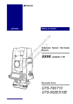
SERVO TOTAL STATION GTS-800
AUTO TRACKING TOTAL STATION GTS-800A
AUTO TRACKING PULSE TOTAL STATION GPT-8000A
APPLICATION SOFTWARE
STANDARD SURVEY 800
Version 3.5
GTS-800 STANDARD SURVEY 800
User Manual
TOPCON CORPORATION
Copyright Statement
The contents of this publication may not be reproduced in any form, by any means, in part
or in whole, without prior written permission of TOPCON Corporation.
Trademarks
In this manual reference is made to the following products.
TOPCON, GTS-6, GTS-7, GTS-800, FC-4, FC-5, FC-6, DRP-1 DRP-2, GTS & ET-2 are
trademarks of TOPCON Corporation.
Civilcad is a trademark of Topcon Australia Pty Ltd.
AutoCAD and DXF are trademarks of Autodesk Inc.
MOSS and GENIO are trademarks of Infrasoft Limited.
Disclaimer
TOPCON Corporation supplies this documentation and software with no representations
or warranty of any kind. TOPCON Corporation assumes no responsibilities and shall have
no liability, consequential or otherwise, of any kind arising from the use of this
documentation or any part thereof.
Table of Contents
1 Introduction......................................................................1-1
2 General Information.........................................................2-1
2.1 Special Keys...............................................................................................2-1
2.2 Menu Selection...........................................................................................2-1
2.3 Job Status Display......................................................................................2-2
2.4 Key Input ....................................................................................................2-2
2.5 Option Screens...........................................................................................2-3
2.6 Horizontal Angle Input ................................................................................2-4
2.7 Recompute Coordinates.............................................................................2-5
3 Getting Started .................................................................3-1
4 Libraries............................................................................4-1
4.1 Point Code Library (CODE) ........................................................................4-1
4.2 Fixed Point Library (PT LIB) .......................................................................4-2
5 Job Files & Job Creation ..................................................5-1
5.1 Create a New Job.......................................................................................5-1
5.2 Open an Existing Job .................................................................................5-2
5.3 Delete a Job ...............................................................................................5-3
6 Recording Options............................................................6-1
6.1 System Options (SYS OPTN) ....................................................................6-1
6.2 Job Options (JOB OPTN)...........................................................................6-4
6.3 Scale Factor (SCALE) ................................................................................6-6
6.4 Temperature and Pressure Input (TEMP/PRES)........................................6-8
7 Occupied Point Details .....................................................7-1
7.1 Occupied Point Input Screen......................................................................7-1
7.1.1 RSCT (Resection) ................................................................................7-2
7.1.2 ELEV (Station Elevation).....................................................................7-7
7.2 Backsight Point Input Screen .....................................................................7-7
7.2.1 Single point backsight .........................................................................7-8
7.2.2 Multiple point backsight .......................................................................7-9
Standard Survey 800
1-1
Introduction
8 Recording Measurements................................................ 8-1
8.1 Back Sight Observations (BS OBS)........................................................... 8-3
8.2 Foresight Observations (FS OBS) ............................................................. 8-4
8.3 Side Shot Observations (SS OBS) ............................................................ 8-6
8.4 Adding String Control............................................................................... 8-13
8.5 Offsets ..................................................................................................... 8-14
9 Cross Section Surveys .................................................... 9-1
10 Editing Data ................................................................. 10-1
10.1 Raw Data ............................................................................................... 10-1
10.2 Point Data .............................................................................................. 10-2
10.3 Fixed Point Data (PT LIB) ...................................................................... 10-4
10.4 Code Library (CODE) ............................................................................ 10-4
10.5 Cut / Fill Data (CUTS)............................................................................ 10-7
11 File Transfer................................................................. 11-1
11.1 Downloading Files to a Computer (SEND)............................................. 11-1
11.1.1 Raw Data......................................................................................... 11-2
11.1.2 Coordinates ..................................................................................... 11-2
11.1.3 DXF Format Files............................................................................. 11-3
11.1.4 Cuts/Fill............................................................................................ 11-3
11.1.5 Cross Sections ................................................................................ 11-3
11.2 Uploading Files to the GTS-800/GPT-8000A (RECEIVE)...................... 11-4
11.2.1 Coordinates ..................................................................................... 11-6
11.2.2 Point Library .................................................................................... 11-6
11.2.3 Code Library .................................................................................... 11-7
11.2.4 Horizontal Alignments...................................................................... 11-7
11.2.5 Vertical Alignments .......................................................................... 11-7
11.2.6 Design Cross Sections .................................................................... 11-8
11.3 Printing Files .......................................................................................... 11-8
11.3.1 Raw Data......................................................................................... 11-9
11.3.2 Coordinates ................................................................................... 11-11
11.3.3 Cut / Fill ......................................................................................... 11-12
11.3.4 Horizontal Alignments.................................................................... 11-12
11.4 Communication Port Parameters......................................................... 11-14
12 Set Out......................................................................... 12-1
12.1 Occ Pt and Bks Pt.................................................................................. 12-3
12.2 Point Setout .......................................................................................... 12-4
1-2
Standard Survey 800
12.3 String Setout...........................................................................................12-8
12.4 Alignment Setout ....................................................................................12-9
12.5 Cross Section Setout............................................................................12-11
12.6 Slope Setout.........................................................................................12-13
13 Traverse Adjustment ....................................................13-1
14 Roads ...........................................................................14-1
14.1 Define Alignment ....................................................................................14-1
14.2 Edit Alignment ........................................................................................14-5
14.3 Define Vertical Curve .............................................................................14-6
14.4 Edit Vertical Curve..................................................................................14-7
15 Cogo.............................................................................15-1
15.1 Intersection.............................................................................................15-1
15.2 4-points Intersection ...............................................................................15-2
15.3 Inverse ...................................................................................................15-3
15.4 Area........................................................................................................15-4
15.4.1 Area using specified points ..............................................................15-4
15.4.2 Area using code ...............................................................................15-6
15.5 Radiation ................................................................................................15-7
15.6 Missing Line Measurement ...................................................................15-8
16 Batterboards................................................................16-1
16.1 Batterboards using two sides .................................................................16-3
16.2 Batterboards using one side...................................................................16-6
17 Tape dimensions .........................................................17-1
18 Monitor .........................................................................18-1
Appendix A Interface ......................................................... A-1
A.1 Serial Interface Cable ............................................................................... A-1
A.2 Parallel Interface Cable............................................................................. A-2
A.3 Cable Connections.................................................................................... A-3
A.4 Com Port Status........................................................................................ A-3
A.5 Data Structure........................................................................................... A-4
A.6 Communication Protocol........................................................................... A-5
A.7 How to Make a BCC ................................................................................. A-7
Standard Survey 800
1-3
Introduction
Appendix B Data Format.....................................................B-1
Appendix C Instructions for Recording MOSS...................C-1
Appendix D How to Calculate Road Alignment..................D-1
Appendix E Resection calculations ....................................E-1
Menu Structure Diagram........................................................ 1
1-4
Standard Survey 800
1 Introduction
Main features of Standard Survey Software 800.
<< For GTS-800A users >>
The MONITOR function of GTS-800A is more comprehensive than that of the
GTS-800. See chapter 18 for details.
Multiple Job Files
Standard Survey Software 800 uses named jobs with separate files for raw data, coordinates
and strings. The jobs are given alpha numeric names with up to eight characters. You may
have many jobs on the system. You may create a new job for storing data, or you may open
an existing job for data storage. The currently selected job is used for storing observed data.
You may also delete job files.
Traverse & Topographic Recording Sequences
Backsight and Foresight observation options allow users to record traverses or sets of
multiple observations in any sequence. Multiple observations of foresights and backsights
are averaged dynamically. A side shot option allows single key collection for topographic
surveys. Traverse and topographic collection may be combined.
Cross Section Surveys
Cross sections may be surveyed with input of chainages and memory of code sequences.
Points collected may be downloaded in chainage, offset and level format.
Offsets
A single offset option is activated by a function key and allows manual entry of
perpendicular offsets, or calculated offsets, including remote elevation from a second angle
reading.
Point Coordinate and String Generation
Coordinates are generated in real-time with optional storage. Stored coordinates are recalled
at occupied stations and used for back bearing calculation. Point code defined in the library
as a line can be downloaded as lines in DXF format. A point its coordinates with respect to a
reference line can be determined.
Standard Survey 800
1-1
Introduction
Horizontal Circle Setting
Backsight bearings may be set on the instrument from calculated coordinates or manual input.
Manual bearing input may be either Whole Circle Bearing or Quadrant format.
Control Point Coordinate Library
Separate control point library is accessible by all jobs for storage of frequently used
coordinates. Control point file may be entered manually, or uploaded from computer.
Point Code Library
Point codes may be selected from the library file.
Edit Data
Raw data, point coordinates, control point coordinates and codes may be edited within the
GTS-800 key panel. If raw data is edited, the previous one is marked as invalidated data in
the downloaded file.
Download to Serial Port or Card Drive
Raw data, coordinates and cross sections can be sent to a computer using a serial cable or
directly copied to the card drive. The format can be selected from default (GTS-7), GTS-6,
FC-5 or MOSS GENIO.
Download DXF Files
Points and lines generated in recorded data may be downloaded in DXF format, with layers
defined by point codes.
Printed Reports
Raw data, coordinates and cut/fill reports may be downloaded for printing from serial port or
parallel port.
Upload from Serial Port or Card Drive
Coordinates for set out, and control point coordinates may be uploaded from a computer
using a serial cable or directly copied to the card drive in default (GTS-7), GTS-6 or MOSS
GENIO format.
1-2
Standard Survey 800
Upload Point Codes from Serial Port or Card Drive
The point code table may be created by uploading codes from a computer.
Upload Roads design data from Serial Port or Card Drive
Horizontal alignment data, Vertical curve data and Cross section data for Alignment set out
may be uploaded in GTS-7 format.
Point Setting Out
The standard setting out program computes bearing and distance, and displays offsets to set
out point after each measurement. Coordinates of points as set out may be saved and
differences down loaded in the cut/fill report.
Note that the scale factor defined under the SETUP will be used in the calculation of setting
out distances. Points with coordinates (North, East) as well as points with coordinates
defined with respect to a reference line can be setout.
String Setting Out
Setting out of points by string (point code) allows the setting out of points on a line created in
design software.
Road Setting Out
Two options allow the setting out of points by chainage and offset from a road alignment.
Complete road designs may be set out from points uploaded in chainage offset and level
format referenced to an alignment.
Traverse Adjustment
The Bowditch (compass rule) adjustment method is used to adjust a recorded traverse. The
traverse is defined by entering start and end points and the intermediate points are determined
from foresight observations.
Resection
Computation of coordinates from known points. The method of calculation is dependent on
the data available. Either two points with angles and distances, or three points with angles
only are required. Where more than three points and up to a maximum of 16 points are
available the least squares method is used. Note that the scale factor defined under the
SETUP function will be used in the calculation.
Standard Survey 800
1-3
Introduction
Occupied Point Elevation Computation
Computation of the occupied point elevation by single observation to a known point.
Intersections
Coordinate calculation from two known points, with either bearings and or distances.
Inverse
Computation of bearing and distance between 2 known points.
Area Calculation
Area calculation of a series of points defined by point code or marked point.
Radiation
Coordinate for a point can be computed by entering the Bearing and Distance.
Missing line measurement
The slope distance, horizontal distance and vertical distance between two points can be
computed.
Batterboards
A program for setting out on building areas. If two points cannot be setout, a batterboard
can be placed in the vicinity. Next the intersection point of the line connecting two setout
points and the batterboard can be found.
Tape dimensions
Tape dimensions is a program which integrates surveying using a total station and a
measuring tape. This program is especially useful when a quick survey of an object is
required.
Monitor
Monitor measurement can be done by using point coordinates with code and string number or
by measured points with code and string number.
1-4
Standard Survey 800
General Information
2 General Information
2.1 Special Keys
The [ENT] key is the most commonly used key. It is used to record measurements, complete
screen input, continue processing after a warning or prompt has been displayed.
The [ESC] key can be used to break out of any function. It will allow you to exit a screen
without saving input, exit a menu and return to a higher level menu, or to break a processing
loop. Function keys are used to access extended screens when a label is displayed on the
bottom row of the screen. When a prompt requiring an [OK] / [CANCL] reply is displayed
you can press [OK] or [ENT] key to reply OK, and press [CANCL] or [ESC] key to reply
CANCEL.
<GTS-800A only>
The [ ] key enables you to aim the prism automatically if the prism is within the predefined
area. The extent can be changed which is also included in the [ ] key menu.
2.2 Menu Selection
SETUP RECORD EDIT
JOB
NEW
SYS OPTN
OPEN
JOB OPTN
DEL
SCALE
TEMP/PRES
XFER
PROG
EXIT
F1
F2
F3
F4
F5
F6
The main menu is displayed across the top line of the screen. Sub menus are displayed as
pop down menus. Use [
] and [
] keys, as defined on the bottom of the screen, to
move between main menu options. Use [
] and [
] keys to move the highlight bar on
the sub menu. Press [ENT] key to select the highlighted sub menu option.
If the sub menu option has further options they will be displayed to the side. The side menu
will be displayed when [ENT] key is pressed. Use [
] and [
] keys to move the
highlight bar and press [ENT] key to select the option. Press [ESC] key to return to the
higher level menu.
Standard Survey 800
2-1
General Information
2.3 Job Status Display
SETUP RECORD
JOB
SYS OPTN
JOB OPTN
SCALE
TEMP/PRES
EDIT
XFER PROG
Job Name
DEFAULT
OCC Pt
A1
BS Pt
A2
FS Pt
115
SS Pt
14
Space
183296
EXIT
F1
F2
F3
F4
F5
F6
The following job status is displayed in the main menu screen.
Job Name :
The current job name
OCC Pt
:
The last Occupied Station
BS Pt
:
The last backsight point number
FS Pt
:
Previous foresight point number
SS Pt
:
Previous side shot point number
Space
:
Memory space available (in Bytes)
2.4 Key Input
New Job
TOPO1
SAMPLE
Job
Description
Name
Instrument
ALPH
SPC
BS
ABC
7
DEF
8
GHI
9
JKL
4
MNO
5
PQR
6
STU
1
VWX
2
YZ
3
#$%
0
!&@
•
ESC
F1
F2
F3
F4
F5
+*/
ENT
NUMERIC KEYS
These can be switched
to ALPHABETIC KEYS
F6
ESCAPE KEY
[ESC]
ENTER KEY
[ENT]
STAR KEY
FUNCTION KEYS
All key input is entered into screens.
Use the cursor keys to move from one field to another.
2-2
Standard Survey 800
General Information
When in a measure option screen, the measurement can be initiated, and point codes can be
accepted as displayed by pressing [ENT] key.
Press [
BS ] to delete the character to the left of the cursor.
When an input field is larger than the screen, the field scrolls to the left. When the field is full,
further input is not accepted.
Some screens will display function key labels. Press the corresponding function key to
access the additional screens.
Alpha characters may be entered by first pressing the function key (F1) when labeled
[ALPH]. This will make the Alpha character set active on the numeric keypad. In any
measure screen or any screen that requires manual input, the (F1) will toggle between
[ALPH] (alphabet) mode and [NUM] (number) mode on the keypad.
For example, to enter a single letter 'A', press the [7] key once. To enter a 'B', press the [7]
key twice, and 'C' requires three key presses. When entering one character and then wait for
about 1 second, the cursor moves to the right automatically. Enter the next letter in the same
manner.
2.5 Option Screens
SETUP
RECORD
EDIT
VA Mode
STN File
Prompt
Output
Display XYZ
F1
F2
XFER
PROG
ZENITH
ON
E/N/Z
GTS-7
OFF
F3
F4
F5
F6
Option screens have fixed input values. To change the options use the [
] and [
]
arrow keys to scroll through the values.
Press [ENT] key to move the highlight bar to the next option.
Press [ENT] key when the highlight bar is on the bottom line of the screen to exit and save
the changes. Press [ESC] key to exit the screen without saving the changes.
Standard Survey 800
2-3
General Information
2.6 Horizontal Angle Input
The horizontal angles can be entered in Whole Circle Bearing or Quadrant Format.
Whole Circle Bearing
N
Whole Circle Bearings are entered as follows;
134.0645 ( 134° 6’ 45” in Degree )
or
134.1125 ( 134g 11c 25cc in Gon )
Quadrant Format
E
Angles are entered as follows;
S45.5315E ( S45° 53’ 15” E in Degree )
S
2-4
or
S45.8875E ( S45g88c75cc E in Gon )
Standard Survey 800
General Information
2.7 Recompute Coordinates
Standard Survey Software 800 retains the Raw data file (measured data) and the Coordinate
data (which is calculated from the measured data after each measurement) separately. When
the raw data is edited the coordinate data may require recomputation.
The coordinate data is automatically recomputed when any output option is executed after
editing raw data.
For example the following changes to the raw data will result in the corresponding changes to
the coordinate data after recomputation;
(1) Occupied Point No.
The coordinates of points observed from this point will be recomputed using the new
Occupied Point data.
(2) Back Sight Point No.
The coordinates of points observed from this station will be recomputed using the new
backsight bearing.
(3) Instrument height / (4) Target height
Z coordinates will be recomputed using the new Instrument height or the new Target
height.
(5) Offsets
The coordinates of a point will be recomputed using the new offset values.
(6) Point code or String Number
The strings are regenerated for all points.
(Remarks)
After editing the Raw Data, the coordinates are not directly recomputed.
The coordinates are recomputed ONLY WHEN an output of coordinate data option is
executed.
This is in order to maintain the efficiency during the measuring or editing operation.
(Operation)
XFER
SEND
POINTS or DXF
COM or CARD
XFER
PRINT
POINTS
COM or PRN
“Re-compute coordinate” is displayed during the recomputation, and when it is
completed, “Ready ?” is displayed.
[OK] (F4)
Actual download can be started.
[CANCL] (F5)
Return to menu without download.
Standard Survey 800
2-5
General Information
2-6
Standard Survey 800
Getting Started
3 Getting Started
01-31-95
F1
F2
16 : 32 : 34
F3
F4
F5
F6
Select “Prog” icon [F1] from the GTS-800 start up menu.
Programs
F1 STDSVY8
p
F2 BS
p
F3 STORE
p
F4 REM
p
F1
F2
F3
4/7
MORE
F4
F5
F6
The program list is displayed. (The list is not always the same as in the figure.)
Select "STDSVY8" to start the Standard Survey Software 800.
SETUP RECORD
JOB
SYS OPTN
JOB OPTN
SCALE
TEMP/PRES
EDIT
XFER PROG
Job Name
DEFAULT
OCC Pt
BS Pt
FS Pt
SS Pt
Space
249344
EXIT
F1
F2
F3
F4
F5
F6
When you start the Standard Survey Software 800 for the first time the current job will be
called DEFAULT. You can record into this job, or you can delete it after creating a new job.
Create a new job, by selecting JOB from the SETUP menu, then NEW. Enter the new job
name. (A valid job name consists of up to 8 characters alpha/numeric).
Standard Survey 800
3-1
Getting Started
Enter the job description, surveyors name, and instrument identification.
Press [ENT] key to move the cursor to the next option. Press [ENT] key when the cursor is
on the bottom line of the screen to exit and save the settings. Press [ESC] key to exit the
screen without saving the settings.
Select JOB OPTN to set the recording options for the job. Change the options to suit your
practice. To change the options use the [
] and [
] arrow keys to scroll through the
values. Press [ENT] key to move the highlight bar to the next option. Press [ENT] key when
the highlight bar is on the bottom line of the screen to exit and save the changes.
Select RECORD to display the recording options.
From the RECORD menu select OCC PT to enter the occupied point details.
Enter a point number, instrument height and point code, then press [ENT] key to return to the
menu. Select BKS PT to enter backsight point details if required.
Select either BS OBS to record the backsight angle, FS OBS to record a foresight point, or
SS OBS to record a series side shot or intermediate sight observations.
EXIT
Press [EXIT] to quit the software.
NOTE:
Sometimes the software does not start if the data files in internal memory are protected or
renamed. If the software fails to open data files, the following messages may be displayed;
Error in Fix Pt File
This message is shown when either the file FIXED.PTS,
FIXED.PTN or FIXED.COD is missing or protected.
Delete these 3 files to initialize the fixed point data.
Error in Code Lib
This message is shown when either the file DEFAULT.LIB,
DEFAULT.LYR or DEFAULT.SYM is protected or corrupted.
Delete these 3 files to initialize the library.
Job xxxxxxxx CORRUPTED!
If the current job is corrupted or one of the files is missing or
protected then the program will prompt for an another job.
Cannot write to Config file!
This message will be shown when the file CONFIG.DAT is
protected and you try to change the current job.
The software will not start if any of the files used are corrupted or protected.
Do not protect any of the files used by the Standard Survey Software 800.
3-2
Standard Survey 800
Libraries
4 Libraries
4.1 Point Code Library (CODE)
The point code library allows you to store commonly used point codes. Codes are grouped by
layer, and can be selected from the library where a code is required in the recording options.
You can create a file in the office using a text editor, or word processor capable of producing text
files, and upload it to the internal memory, or you can edit the library file in the internal memory.
SETUP
RECORD
EDIT
XFER
PROG
ROAD
SERVICE
VEG
ADD
REN
DEL
F1
F2
F3
F4
F5
F6
See EDIT/CODE (section 10.4) for details on how to create a code library manually.
Standard Survey 800
4-1
Libraries
4.2 Fixed Point Library (PT LIB)
SETUP
RECORD
EDIT
Pt No
North
East
Elev
Pt Code
XFER
PROG
9001
1004.662
1005.752
95.029
PT
STRT
END
FIND
PREV
NEXT
F1
F2
F3
F4
F5
P2
F6
The fixed point library allows you to store coordinates for commonly used points, or control
stations. This file is accessed by any job when the STN FILE option is “ON“ (see SYS OPTN).
When you enter the details for an occupied point, if the job file does not contain coordinates for
the point, the fixed point file is searched. If the point is found in the fixed point library those
coordinates are used, and written into the raw data as though they were entered manually. If no
point is found in the fixed point library then the coordinates must be entered manually. Press
[ENT] key to move the cursor to the next option.
Press [ENT] key when the cursor is on the bottom line of the screen to exit and save the settings.
Press [ESC] key to exit the screen without saving the settings.
The fixed point library may be created by uploading points from a computer, similar to uploading
job coordinate files, or may be created manually by the edit fixed point option.
4-2
Standard Survey 800
Job Files & Job Creation
5 Job Files & Job Creation
To create a new job, open an existing job, or delete a job, select JOB from the SETUP menu.
SETUP
JOB
SYS OPTN
JOB OPTN
SCALE
TEMP/PRES
5.1 Create a New Job
Select NEW to create a new job.
SETUP
JOB
NEW
SYS OPTN OPEN
JOB OPTN DEL
SCALE
TEMP/PRES
New Job
Job
TOPO1
SAMPLE
T.H.O
GX0005
Description
Name
Instrument
NUM
F1
F2
F3
F4
SPC
BS
F5
F6
Enter the new job name. A job name has a maximum of 8 characters and should be made
up from the letters A-Z, numbers 0-9 and the minus sign (-) only. A job name can not
contain a space or any of the special characters. The minus sign cannot be entered as the
first character of the job name. Press [ENT] key to move the cursor to the next option.
Enter the job details. Press [ENT] key when the cursor is on the bottom line of the screen to
exit and save the settings. Press [ESC] key to exit the screen without saving the settings.
The new job will become the current job. If the job name already exists, the message “Job
Already Exists” is displayed.
Select OPEN option to see a list of current jobs before creating the new job if you are not
sure which jobs currently exist.
Standard Survey 800
5-1
Job Files & Job Creation
NOTE:
The GTS-800 can record a maximum of 304 files in the internal memory.
When a JOB is created, the Standard Survey Software 800 creates more than 5
files automatically. When the cross section data, set out data, alignment data and
so on is created, more files are added to the job. If more than about 30 JOBs are
recorded, you may not be able to create a new JOB. In this case, create a new
JOB after deleting a JOB which is not necessary any more.
5.2 Open an Existing Job
Select OPEN from the file menu.
SETUP
JOB
NEW
SYS OPTN OPEN
JOB OPTN DEL
SCALE
TEMP/PRES
The file display lists all the files stored in the internal memory. The current job is displayed
at the top of the screen.
SETUP
RECORD
EDIT
Select Job
F1
Use [
Use [
] or [
F2
XFER
PROG
DEFAULT
DEFAULT
TRAV
HV
TOPO
H
TOPO2
ROAD
HVX
Current Job
F3
F4
F5
F6
] keys to move the hi-light bar to select a file to open.
] to scroll through additional pages. When the required job is highlighted press
[ENT] key to make the job current and return to the menu.
If Alignment data exists in a Job, the job list can display H, V and X behind the job name.
H: Horizontal Alignment data
V: Vertical Alignment data
X: Cross section data
C: Cut / Fill Report data
5-2
Standard Survey 800
Job Files & Job Creation
5.3 Delete a Job
To delete a job from the internal memory select DEL from the file menu.
SETUP
JOB
NEW
SYS OPTN OPEN
JOB OPTN DEL
SCALE
TEMP/PRES
As with the open file, the display lists all the files stored in the internal memory. The current
job is displayed on top of the screen.
SETUP
RECORD
EDIT
Select Job
F2
PROG
DEFAULT
DEFAULT
TRAV
HV
TOPO
H
TOPO2
ROAD
HVX
Current Job
F1
XFER
F3
F4
F5
F6
To delete a job from the internal memory, move the hi-light bar to the required file and press
[ENT] key.
SETUP
RECORD
EDIT
XFER
PROG
Delete Job
TRAV
ALL
F1
PTS
HAL
F2
F3
HV
VC
XSEC
P2
PTLIB
CUTS
P1
F4
F5
ALL
: Delete all files
PTS
: Delete Points file
HAL
: Delete Horizontal ALignment file
VC
: Delete Vertical Curve file
F6
XSEC : Delete Cross section Alignment file
PTLIB : Delete Fixed Point Library (PT LIB)
CUTS : Delete Set out coordinates file
Standard Survey 800
5-3
Job Files & Job Creation
The prompt "Are you sure? " will be displayed. Press [OK] or [ENT] key to delete the file,
or [CANCL] or [ESC] key to return to the menu without deleting the file.
The current job cannot be deleted if you select [ALL].
NOTE:
If points file data is deleted with some Cut / Fill data remained, the Cut / Fill
can not be shown correctly in EDIT-CUTS and PRINT-CUTS.
5-4
Standard Survey 800
Recording Options
6 Recording Options
6.1 System Options (SYS OPTN)
To set the system options choose SYS OPTN from the SETUP menu.
SETUP
JOB
SYS OPTN
JOB OPTN
SCALE
TEMP/PRES
SETUP
RECORD EDIT
VA Mode
STN File
Prompt
Output
Display XYZ
F1
F2
XFER
PROG
ZENITH
ON
E/N/Z
GTS-7
OFF
F3
F4
F5
F6
VA Mode
ZENITH or LEVEL
STN File
ON or OFF
Prompt
N/E/Z or E/N/Z
Output
GTS-7, GTS-6, FC-5 or MOSS
Display XYZ
ON or OFF
System options apply to all jobs in the internal memory.
If changes are made they affect all jobs.
To change the options use the [
] and [
] arrow keys to scroll through the values.
Press [ENT] key to move the highlight bar to the next option. Press [ENT] key when the
highlight bar is on the bottom line of the screen to exit and save the changes. Press [ESC]
key to exit the screen without saving the changes.
VA Mode
The vertical angle mode specifies where vertical angles are read from.
Changing this option will set the instrument.
a) ZENITH
The vertical angle is 90 degrees face left to horizontal and decreasing towards Zenith.
Standard Survey 800
6-1
Recording Options
b) LEVEL
The vertical angle is 0 degrees face left to horizontal and increases towards Zenith.
Station File (STN File)
The station file (STN FILE) or fixed point library allows coordinates of frequently used
control points to be saved and accessed by all jobs. See Library for details on how to create a
fixed point file.
a) ON
If the station file option is ON then the fixed point file will be scanned for coordinates of
occupied stations and backsight points before prompting for the coordinates, when there is
not a coordinate for the point in the current job.
When the same point number is saved both in POINT and PTLIB data base, the data in
POINTS is recalled and used for occupied station and backsight point.
b) OFF
If the station file is OFF the fixed point file is not searched for coordinates of occupied
stations and backsight points.
Prompts
The order of prompts in the coordinate entry and editing screens may be selected with this
option.
a) N/E/Z
Select N/E/Z to display prompts in NORTH, EAST and ELEVATION order.
b) E/N/Z
Select E/N/Z to display prompts in EAST, NORTH and ELEVATION order.
NOTE :
The coordinate output format is always E,N,Z except in PRINT POINT when
GTS-7 Output is selected.
Output
The Output option controls the format for downloaded and uploaded data, which may be
formatted in a number of different formats, providing downward compatibility with other
TOPCON data collectors. The default format for the GTS-800 is the Topcon GTS-7 format.
If you select GTS-6, then the raw format will be the same as the Topcon GTS-6 instruments.
a) GTS-7
Select GTS-7 (or FC-6). If using TOPCON DRP-1/ DRP2 or Civilcad packages.
6-2
Standard Survey 800
Recording Options
b) GTS-6
Select GTS-6 to download data in GTS-6 compatible format.
The downloaded raw data with the SEND option will be unformatted, with the PRINT
option it will be formatted.
c) FC-5
Select FC-5 to download data in FC-5 compatible format. The format is the FC-5 SELECT
mode. (The function menu [FUNC] [7] of FC-5 will enable you to select the data to record.)
Not all information recorded can be downloaded in FC-5 format.
Raw data downloaded with the SEND option will be unformatted, data downloaded with the
PRINT option will be formatted.
d) MOSS
Both MOSS raw data and MOSS GENIO string format files may be downloaded.
The XYZ download option produces GENIO string files. The string number field and point
code are combined to generate strings.
If downloading RAW data in MOSS format the string control fields may be used to enter the
MOSS data fields.
NOTE:
This option controls the format required when uploading points. (RECEIVE
POINTS or PT LIB), but all the others control with GTS-7 format.
Display XYZ
The coordinates are displayed when you record H/V/SD or H/HD/VD data for FS OBS /
SS OBS / X-SECT in case you select XYZ File is ON in JOB OPTN and Display XYZ
is ON in SYS OPTN.
SETUP
RECORD
EDIT
North
East
Elev
XFER
PROG
( Remarks )
It is not possible to cancel the
26.905
10.105
0.195
recording of XYZ data in this
display, even if you press the
[ESC] key.
OK
F1
F2
F3
F4
F5
F6
a) ON
If the Display XYZ is ON the coordinates are displayed.
b) OFF
If the Display XYZ is OFF the coordinates are not displayed.
Standard Survey 800
6-3
Recording Options
6.2 Job Options (JOB OPTN)
The job options apply to each job, and may be changed from one job to another.
SETUP
JOB
SYS OPTN
JOB OPTN
SCALE
TEMP/PRES
The information is stored as part of the raw data for the job. To set job options select JOB
OPTN from the SETUP menu.
SETUP
RECORD
EDIT
Units
Angles
Prompt Bks
XYZ File
Save Set
F1
F2
XFER
PROG
METERS
DEGREES
ON
ON
OFF
F3
F4
F5
Units
METERS or FEET
Angles
GON or DEGREES
Prompt Bks
ON or OFF
XYZ File
ON or OFF
Save Set
ON or OFF
To change the options use the [
] and [
F6
] arrow keys to scroll through the values.
Press [ENT] key to move the highlight bar to the next option. Press [ENT] key when the
highlight bar is on the bottom line of the screen to exit and save the changes. Press [ESC]
key to exit the screen without saving the changes.
When changing job options only the current job is changed.
When an existing job is opened the options are restored to what they were when the job was
last used.
Units
This specifies the unit of distance that will be included in the unit record of the downloaded
data, and must correspond to the settings of the instrument.
a) METERS
The unit of distances is meters.
6-4
Standard Survey 800
Recording Options
b) FEET
The unit of distances is feet and decimal feet.
Coordinates are stored unitless and calculated from the actual distances measured.
Angles
This specifies the units used to display and download recorded angles.
Angles are stored internally in degrees for calculation purposes, and may be displayed or
downloaded in either unit regardless of the units used in measurement.
a) GON
Angles are displayed and downloaded in grads in the format GGG.GGGG.
Manual entry must be entered in this format also.
b) DEGREES
Angles are displayed in degrees minutes and seconds, with the format DDD.MMSS.
Manually entered angles should be entered in this format.
Prompt Bks
If the prompt Bks option is ON the user is forced to enter a backsight point after each new
occupied station, before a foresight or side shot can be taken.
XYZ File
Coordinates may be automatically calculated and saved when you measure H/V/SD or
H/HD/VD mode. If you intend downloading coordinates, adjusting a traverse, or to use the
computed backsight bearing to set the instrument then this option should be ON.
a) ON
Set this option to ON to compute and save coordinates.
b) OFF
If you do not wish to store computed coordinates, set this option to OFF.
If the XYZ option is OFF, coordinates for occupied stations are not required.
Save Setout
Coordinates of points that have been setout may be saved for printing in the CUT/FILL report.
This report lists each point setout with the design coordinates and setout coordinates and
shows cut or fill height.
NOTE :
Road Alignment Setout and X-SECTS data can not print CUT/FILL reports.
Standard Survey 800
6-5
Recording Options
a) ON
Set to ON to save coordinates. Coordinates are saved when [ENT] key is pressed in any of
the setout options.
b) OFF
Set to OFF if you do not wish to save the setout coordinates.
6.3 Scale Factor (SCALE)
Measured horizontal distances are multiplied by the scale factor in coordinate calculation.
The scale factor to be used may be entered with this option.
The raw data is not altered by the scale factor.
SETUP
JOB
SYS OPTN
JOB OPTN
SCALE
TEMP/PRES
To enter a scale factor select SCALE from the SETUP menu.
SETUP
RECORD
EDIT
Scale
Elevation (m)
Tolerance
XFER
1 .000000
0.000
15
NUM
F1
F2
PROG
F3
F4
SPC
BS
F5
F6
Enter the scale factor (Scale) and mean elevation (Elevation) into the screen.
Press [ENT] key to move the cursor to the next option. Press [ENT] key when the cursor is
on the bottom line of the screen to exit and save the settings. Press [ESC] key to exit the
screen without saving the settings.
The downloaded raw data (in GTS-7 format) will contain a scale factor record.
The following grid factor f ' is used to calculate coordinates.
f ' = f * R/(R+h)
f
: Scale
h : Elevation
R : The Radius of the Earth (= 6,372,000m)
6-6
Standard Survey 800
Recording Options
When measuring face left and right, the program will calculate the tolerance value. If over
the value comparing with manual input value, the warning message will display after
calculating while measuring.
The following value “he” is used to comparing with manual input tolerance.
he = | h − ( h’ − 180) |
h
: angle of face right
h’
: angle of face left
NOTE: 1. Scale can be entered in the following ranges;
0.900000 — 1.100000
Scale is rounded to 6 decimal places. The default scale factor is 1.00000.
2. Elevation can be entered in meters only . The ranges are as follows;
-1000.000 — 10000.000
Elevation is rounded to 3 decimal places. The default elevation is 0.
3. Tolerance can be entered in the following ranges;
0 — 300 [sec] ( 92.59 [mgon] )
The default tolerance is 15 [sec] ( 4.63 [mgon] ).
4. Scale is used in the calculation of coordinates and except COGO menu and
the calculation of horizontal distance to the Setout point.
5. Calculation of Z coordinate is not influenced even if it is applied to grid factor.
Standard Survey 800
6-7
Recording Options
6.4 Temperature and Pressure Input (TEMP/PRES)
To enter temperature and pressure select the TEMP option in the SETUP menu.
SETUP
JOB
SYS OPTN
JOB OPTN
SCALE
TEMP/PRES
SETUP
RECORD
EDIT
XFER
24
760
Temp
Press
NUM
F1
F2
PROG
F3
F4
SPC
BS
F5
F6
The temperature and pressure screen will be displayed.
Enter the temperature value (Temp) and the pressure value (Press).
Press [ENT] key to move the cursor to the next option. Press [ENT] key when the cursor is
on the bottom line of the screen to exit and save the settings. Press [ESC] key to exit the
screen without saving the settings.
NOTE:
Temperature and pressure are just stored in the raw data and never affect the
GTS-800 parameters nor PPM calculation.
6-8
Standard Survey 800
Occupied Point Details
7 Occupied Point Details
7.1 Occupied Point Input Screen
Occupied point details are entered by selecting OCC PT from the RECORD menu.
RECORD
OCC PT
BKS PT
BS OBS
FS OBS
SS OBS
X-SECT
The occupied point is normally entered each time the instrument is set up and before you
begin observations.
Select OCC PT and the occupied point screen will be displayed.
Occupied point
A1
1.520
PT
Occ Pt
Ins Ht
Pt Code
ALPH
F1
SPC
P2
RSCT
ELEV
P1
F4
F5
BS
F2
F3
F6
Enter the point identifier for the occupied point (Occ Pt - maximum 8 characters), the
height of instrument (Ins Ht), and the point code (Pt Code).
Press [ENT] key to move the cursor to the next option. Press [ENT] key when the cursor is
on the bottom line of the screen to exit and save the settings. Press [ESC] key to exit the
screen without saving the settings.
If the XYZ FILE flag is ON and coordinates do not exist in the point file or fixed point file
then the coordinate entry screen is displayed.
Standard Survey 800
7-1
Occupied Point Details
SETUP
RECORD
EDIT XFER
A1
Pt No
North
East
Elev
Pt Code
PT
NUM
F1
F2
PROG
F3
F4
SPC
BS
F5
F6
Enter the easting (East) northing (North) and elevation (Elev) of the point.
Press [ENT] key to move the cursor to the next option. Press [ENT] key when the cursor is
on the bottom line of the screen to exit and save the settings. Press [ESC] key to exit the
screen without saving the settings.
If the point exists both in the point file and fixed point file, then coordinates from the point
file will be used.
7.1.1 RSCT (Resection)
If the coordinates of an occupied point are unknown, a resection can be performed to
compute these coordinates. A resection involves the measurements from an occupied point
to several other points with known coordinates. It is possible to perform a resection by
measuring angles and distances or by measuring angles only. The type of measurements
influences the minimum number of observations needed to perform a resection. In case of
angle as well as distance measurements a minimum of 2 observations are required, by
measuring angles only a minimum of 3 observations should be performed.
Select [RSCT] in the Occupied Point screen. The following screen will be displayed:
Resection
e1
Scale
F1
7-2
F2
DEL
ADD
NEZ
F3
F4
F5
PARAM
F6
Standard Survey 800
Occupied Point Details
On the lower side of the screen discrepancies (e1) or the standard deviation in N, E and Z
direction (sN, sE, sZ) of the occupied point will be displayed. Discrepancies will be shown
in case two distance measurements have been performed. They are calculated using the
following equations:
e1 = HD12, calculated using measurements – HD12, calculated using known coordinates
where:HD12
denotes the horizontal distance between the first and second point.
In case 3 or more distance measurements or 4 or more angle measurements have been
performed, the standard deviations will be displayed instead of the discrepancies.
On the upper side of the screen a box is shown, which will contain the number of the points
to which measurements have been performed and the residuals of these measurements. The
box is empty since no measurements have yet been performed. Press [ADD] to add a new
measurement to the list of resection measurements. The following screen will be shown.
Resection
Pt No
R Ht
NUM
F1
2000
1.70
HA
VA
SD
MODE MEAS
BS
F2
40.5650
19.4250
F3
F4
F5
F6
Enter the correct point number. By pressing [MODE] the measuring mode can be changed.
By selecting [MEAS] a measurement will be performed, but this measurement will not be
saved and will not be used for the resection calculation. In order to perform a measurement
which will be added to the list of measurements, select [ENT] key. If the coordinates of this
point are still unknown, the user will be asked to enter these coordinates. Again the main
resection screen will be shown, but now the point number to which has been measured is
shown in the box.
Standard Survey 800
7-3
Occupied Point Details
In case 3 angle measurements or 2 angle and distance measurements have been performed,
the coordinates of the occupied point can be displayed by pressing [NEZ]. The box on the
right will contain point numbers as well as residuals.
Resection
2000
+0.0001
+0.1400
2001
+0.0100
−0.0202
2002
+0.0003
−0.1300
2003
+0.0001
+0.3403
sN 0.0005
sE 0.0010
Scale
DEL
ADD
F1
F2
F3
−0.0001
+0.0103
+0.0002
−0.0101
sZ 0.0224
NEZ
F4
PARAM
F5
F6
The number of residuals shown depends on the parameters selected. Generally, the worst
observation will have the largest residual. This observation can be deleted by placing the
bar on this observation using the arrow key and then pressing [DEL]. The observation is
removed from the list. The coordinates of the occupied point, its standard deviation or
discrepancies and the residuals of the remaining observations are automatically recomputed.
By selecting [PARAM], the parameters which are calculated during resection can be
selected. The following screen will be shown:
Resection
OFF
OFF
OFF
OFF
OFF
Calculate level
Store res meas
Calculate scale
Store calc scale
Calculate Bkb
F1
F2
F3
F4
F5
F6
It is possible to select whether the level of the occupied point, a scale factor or the backsight
bearing (‘Calculate Bkb’) should be calculated. Furthermore it is possible to select whether
the calculated scale or the measurements which have been performed (‘Store res meas’)
should be stored. Pressing [ENT] key when the cursor is at the bottom line results in
returning to the main resection screen, saving the changes made and (re)calculation of the
occupied point, residuals and the required parameters.
7-4
Standard Survey 800
Occupied Point Details
Pressing [ENT] key in case the main resection screen is shown will result in leaving this
screen and saving of the coordinates of the occupied point. In case ‘Store res meas’ was
turned on in [PARAM], the measurements which have been performed and which are shown
in the box will be saved as well.
In case ‘Calculate Bkb’ in [PARAM] was turned on, the backsight bearing will be calculated
and set by pressing [ENT] key and leaving the main resection screen. The computation will
use all measurements which are shown in the box. In order to calculate a backsight bearing
of high quality:
1. the residuals of the horizontal angle should have low values.
2. the user shouldn’t change the horizontal angle when leaving the main resection
screen.
NOTE:
1. The measurements can be performed in any order. The point numbers shown in the box
in the main resection screen will be sorted by horizontal angle.
2. When 3 points are used for resection using angle measurements only, you must consider
the "danger circle".
P2
eg; If P1, P2, P3 and Occpt fall on the circle,
the result can not be computed.
P3
If the point is near the circle then the
result is unstable.
P1
Occpt
3. Residuals are useful to avoid that observations of low quality will be used for the
resection computation. However, in case of a small number of observations or a bad
geometrical constellation of the points it is possible that one bad observation influences
several residuals.
4. The unit of the residuals is similar to the unit of the measurements performed.
However, the residual of the horizontal and vertical angle is always displayed in decimals.
5. In case a point number has more than 6 digits, only the last 6 digits will be shown in the
box in the main resection screen. The point number will be stored using the original
number of digits.
Standard Survey 800
7-5
Occupied Point Details
6. The error message ‘Invalid scale’ is shown if the calculated scale is not within the
range 0.9 – 1.1 and has to be stored.
7. More than one measurement to the same point can be performed during resection. In
that case the character ‘*’ is placed behind the point number. The average of the
measurements to the same point is used for the calculations.
8. Equations for the calculation of the residuals, the scale and the backsight bearing are
explained in appendix E.
9. The following table shows which residuals will be shown (∆H denotes the residual of the
horizontal angle, ∆V the residual of the vertical angle, ∆SD the residual of the slope
distance).
Calc. Level: On
Calc. Level: Off
Meas. Mode: H/V/SD
∆H, ∆V, ∆SD
∆H
Meas. Mode: H/V
∆H, ∆V
∆H
Table 7.1:
The residuals which will be displayed depends on the measuring
mode and whether level is calculated.
10. When 2 points are used for resection using 2 angles and one distance measurements, you
must measure shorter distance. If you measured longer distance, you can not get the
correct result. (The residual of SD should have high values.)
7-6
Standard Survey 800
Occupied Point Details
7.1.2 ELEV (Station Elevation)
If the elevation of a point to be occupied is not known but a point of known elevation can
be observed, then the station elevation can be computed.
To compute the occupied point elevation select [ELEV] from page 2 of the occupied point
menu.
Occupied point
Pt No
R Ht
R01
1.20
NUM
BS
F1
F2
HA
VA
SD
40.5650
19.4250
MODE MEAS
F3
F4
F5
F6
Enter the point number for the known point, and the target height. If there is no coordinate
for the point the coordinate entry screen will be displayed. Enter the coordinates and press
[ENT] key to save the information.
The measure screen will be displayed. Press [ENT] key to record the observation.
The coordinate entry screen will be displayed.
Enter the easting, and northing if required. The computed elevation will be shown.
7.2 Backsight Point Input Screen
After entering the occupied point details, you may want to enter your backsight station
details. The backsight point screen is used to set the backsight point, and backsight bearing.
RECORD
OCC PT
BKS PT
BS OBS
FS OBS
SS OBS
X-SECT
Select BKS PT from the RECORD menu.
Standard Survey 800
7-7
Occupied Point Details
SETUP
RECORD
EDIT
F1
SPC
BS
F2
PROG
A2
Bks Pt
R Ht
NUM
XFER
F3
F4
M.BKS
F5
F6
In case a backsight orientation using a single target is desired, enter the backsight point
number (Bks Pt) in the screen, and press [ENT] key. The backsight orientation using a
single point is explained in paragraph 7.2.1. Press [M.BKS] in case you want to perform a
backsight orientation using multiple points. The multiple backsight orientation is explained
in paragraph 7.2.2.
7.2.1 Single point backsight
If a coordinate for the backsight point is stored then the computed back bearing will be
displayed. If the XYZ FILE flag is ON and there is no coordinate for the point the
coordinate entry screen will be displayed. Enter the coordinates or press [ESC] key to
bypass this screen and enter the bearing manually.
SETUP
RECORD
EDIT
XFER
PROG
A2
90.0000
314.5012
Bks Pt
Bks Brg
Horiz
Sight BS Point
SET
ZERO
F1
F2
CHECK
F3
F4
F5
F6
When the back bearing is displayed the screen has two function key options;
SET, and ZERO
These function keys are used to set the horizontal circle of the instrument, and to initialize
the internal backsight direction used in coordinate calculations. Sight the backsight point
and press one of the function keys.
7-8
Standard Survey 800
Occupied Point Details
a) SET
Use the [SET] function to set the back bearing on the instrument.
b) ZERO
Use the [ZERO] key to set zero on the instrument.
c) CHECK
Use the [CHECK] key to check the coordinates of backsight point by measuring the slope
distance.
When [ENT] key is pressed the current displayed horizontal angle is recorded as the initial
backsight direction along with the computed or manually entered back bearing.
All coordinate calculations are based on the measured angle between backsight and
foresight (or side shot). A backsight observation over-rides the initial backsight direction,
otherwise the initial value is used in the calculation.
If no backsight point is entered then the backsight bearing, and initial backsight direction
are set to zero. This assumes the horizontal circle has been set manually and the recorded
observations are bearings.
Once you have set the backsight point number and the back bearing, the instrument will be
orientated and ready to observe.
7.2.2 Multiple point backsight
A backsight orientation with a high degree of reliability can be achieved by performing a
multiple point backsight. By selecting [M.BKS] in the BKS PT screen, the following screen
will be shown.
Multiple Backsight
F1
Standard Survey 800
F2
DEL
ADD
F3
F4
F5
F6
7-9
Occupied Point Details
On the upper side of the screen a box is shown, which will contain the number of the points
to which measurements have been performed and the residuals of these measurements. The
box is empty since no measurements have yet been performed. Press [ADD] to add a new
measurement to the list of multiple point backsight measurements. The following screen
will be shown.
Multiple Backsight
Pt No
R Ht
NUM
F1
2000
1.70
HA
VA
MODE MEAS
BS
F2
40.5650
19.4250
F3
F4
F5
F6
Enter the correct point number. By pressing [MODE] the measuring mode can be changed.
By selecting [MEAS] a measurement will be performed, but this measurement will not be
saved and will not be used for the calculation of the backsight. In order to perform a
measurement which will be added to the list of measurements, select [ENT] key. If the
coordinates of this point are still unknown, the user will be asked to enter these coordinates.
Again the main multiple backsight screen will be shown, but now the point number to which
has been measured plus the residual of the horizontal angle is shown in the box.
2000
2001
2002
2003
F1
Multiple Backsight
+0.0001
+0.0100
+0.0003
+0.0001
F2
DEL
ADD
F3
F4
F5
F6
Generally, the worst observation will have the largest residual. This observation can be
deleted by placing the bar on this observation using the arrow key and then pressing [DEL].
The observation is removed from the list. The residuals of the remaining observations are
automatically recomputed.
7-10
Standard Survey 800
Occupied Point Details
The backsight bearing will be calculated and set by pressing [ENT] key, the display will
return to the main menu. The computation of the backsight will use all measurements which
are shown in the box. In order to calculate a backsight bearing of high reliability the
following points should be noted:
1. the residuals of the horizontal angle should have low values.
2. the user shouldn’t change the horizontal angle when leaving the main multiple point
backsight screen.
NOTE:
1. The measurements can be performed in any order. The point numbers shown in the box in
the multiple backsight screen will be sorted by horizontal angle.
2. Residuals are useful to avoid that observations of low quality will be used for the
calculation of the backsight. However, in case of a small number of observations it is
possible that one bad observation influences several residuals.
3. In case a point number has more than 6 digits, only the last 6 digits will be shown in the
box in the multiple backsight screen. The point number will be stored using the original
number of digits.
4. More than one measurement to the same point can be performed. In that case the
character ‘*’ is placed behind the point number. The average of the measurements to
the same point is used for the calculations.
5. Equations for the calculation of the residual of the horizontal angle and the backsight
bearing are explained in appendix E.
6. In case a resection is being performed, it is not necessary to perform a multiple point
backsight afterwards. By selecting ‘Calculate Bkb’ = ON, a multiple point backsight
will be performed using the resection measurements.
Standard Survey 800
7-11
Occupied Point Details
7-12
Standard Survey 800
Recording Measurements
8 Recording Measurements
To record measurements select a measurement type from the RECORD menu.
The measurement types available are BS OBS (backsight observation), FS OBS (foresight
observation) and SS OBS (sideshot observation).
SETUP
RECORD
Pt No
R Ht
Code
1001
EDIT
XFER
HA
VA
SD
PROG
40.5650
19.4250
( Example ) FS OBS
NUM
BS
LIB
NOTE
FACE
F1
F2
F3
F4
MEAS
P2
MODE
P1
F5
F6
These are 2 options for the measurement process:
1. [ENT]
Using [ENT] key allows a recording with single key press, but point number, code and
reflector height must be entered before measurement. When [ENT] key is pressed
without first taking a measurement, measurement is initiated and the data recorded at the
completion of the measurement process.
2. [MEAS] + [ENT]
[MEAS] initiates the measurement process and will display measured data, but the data
is NOT YET stored in the job file. The point number, code and reflector height may be
entered after the measurement process is completed. Press [ENT] key to save the data.
[GPT-8000A only]
When measuring distance(“<” is moving), [MEAS] key switches prism/non-prism mode.
When distance has been measured using the [MEAS] the instrument can be turned and the HA
updated. The new HA will be recorded when the [ENT] key is pressed.
This allows an offset measurement to be recorded without any additional functions.
Press [ESC] key to return to the initial measurement screen.
Standard Survey 800
8-1
Recording Measurements
[MODE]
This allows you to choose the measurement mode, EDM mode and measure repeat mode.
•
Meas Mode ( H/V/SD or H/V or H/HD/VD )
The measurement mode determines the type of data recorded.
H=horizontal angle
V=vertical angle
SD=slope distance
HD=horizontal distance
VD=vertical height difference
Select H/V/SD or H/HD/VD if you need to record in distance mode.
•
EDM mode ( FINE or COARSE )
•
REP mode ( SINGLE or REPEAT )
NOTE: Display XYZ
The coordinates are displayed when you record H/V/SD or H/HD/VD data for FS OBS /
SS OBS / X-SECT in case you select XYZ File is ON in JOB OPTN and Display XYZ
is ON in SYS OPTN.
SETUP
RECORD
EDIT
North
East
Elev
XFER
PROG
( Remarks )
It is not possible to cancel the
26.905
10.105
0.195
recording of XYZ data in this
display, even if you press the
[ESC] key.
OK
F1
F2
F3
F4
F5
F6
[ALPH] / [NUM] (F1)
[ALPH]/[NUM] (F1) toggles between alpha/numeric modes. When the label shows [ALPH] the
mode is alpha and when [NUM] is displayed the mode is numeric.
[P2]
[P2] selects page 2 of the function key menu.
[NOTE]
The [NOTE] function allows the addition of a note record. Press [P2] and then [NOTE] to enter
a note at any time during recording.
8-2
Standard Survey 800
Recording Measurements
8.1 Back Sight Observations (BS OBS)
The backsight angle is measured with the Prompt BS OBS option. Only a horizontal angle
is required for internal coordinate calculations, however the mode may be set to record
distances also.
RECORD
OCC PT
BKS PT
BS OBS
FS OBS
SS OBS
X-SECT
Press [ENT] key, and the displayed horizontal and vertical angles will be recorded.
The previously entered backsight point number is recorded automatically.
No coordinate is computed for the backsight point.
SETUP
RECORD
Pt No
R Ht
1001
NUM
EDIT
XFER
HA
VA
BS
NOTE
F1
F2
F3
F4
PROG
40.5650
19.4250
MEAS
P2
MODE
P1
F5
F6
When a backsight angle is recorded, the angle will be used in subsequent
coordinate calculations.
Standard Survey 800
8-3
Recording Measurements
8.2 Foresight Observations (FS OBS)
RECORD
OCC PT
BKS PT
BS OBS
FS OBS
SS OBS
X-SECT
The foresight option is used to record observations to the next traverse point, or for
collecting a set of foresight points with multiple observations for averaging. An unlimited
number of observations can be made to each foresight point, with a maximum of 16
foresight points in a set.
After collecting a set of foresights, the GTS-800 will automatically reverse face and point to
each point in the set, in reverse order then return to the backsight point when the FACE
option is selected.
Both foresight and backsight observations are averaged, after converting to face left, and
coordinates are computed based on the averaged angles.
When collecting multiple foresight points, and the horizontal circle is changed between sets,
you must record a complete set of foresight observations and a backsight observation for
each change in the horizontal circle, otherwise the average angle calculated will not be
correct.
SETUP
RECORD
Pt No
R Ht
Code
1001
NUM
EDIT
XFER
HA
VA
SD
BS
LIB
NOTE
F1
F2
FACE
F3
F4
PROG
40.5650
19.4250
MEAS
P2
MODE
P1
F5
F6
a) LIB
The LIB function allows codes to be selected from the point code library.
Press the function key, and a pick list of layers will be displayed. Pick a layer from the
list and the codes for that layer will be displayed.
8-4
Standard Survey 800
Recording Measurements
Codes can be selected by pressing the key shown beside the code on the numeric keypad
or by using the arrow keys to highlight the required code, followed by pressing [ENT]
key. The code will be automatically placed in the point code field.
b)FACE
When the Face option is selected the GTS-800 will reverse the face, and after each
observation automatically rotate to previous point in the set by using servomotor. When
observations have been made to all points in the set it will point to the backsight point.
Standard Survey 800
8-5
Recording Measurements
8.3 Side Shot Observations (SS OBS)
The side shot (intermediate site) option allows recording of points with automatically
incrementing point numbers.
RECORD
OCC PT
BKS PT
BS OBS
FS OBS
SS OBS
X-SECT
Side shot observations are not averaged and coordinates are computed using the last
recorded backsight angle (converted to face left).
SETUP
RECORD
Pt No
R Ht
Code
Str
1001
NUM
BS
EDIT
CTRL
HV R.
F1
EDIT
XFER
PROG
40.5650
19.4250
HA
VA
SD
MEAS
P2
OFFS
NOTE
LIB
P3
PLANE
MODE
PTL
P1
F2
F3
F4
F5
F6
After the observation is stored the measure screen will appear again with the point number
incremented and ready for the next observation. Code and reflector height default to the
values used for the previous point. This allows single key press operation for measurement
and recording, but requires point number, code and reflector height to be entered before
measurement.
a) LIB
The [LIB] function allows codes to be selected from the group (or layer). Press the
function key labeled [LIB], and select a layer from the list displayed.
SETUP
1
2
3
4
5
6
RECORD
EDIT
XFER
PROG
7
8
9
0
.
-
TREE
PG-DN PG-UP
F1
8-6
F2
F3
F4
F5
F6
Standard Survey 800
Recording Measurements
Use the arrow keys to choose the required layer. When the layer you wish to use is
highlighted, press [ENT] key and move to the screen selecting code.
SETUP
RECORD
EDIT
VEG
BDY
1
2
3
4
5
6
XFER
PROG
7
8
9
0
.
PG-DN PG-UP
F1
F2
F3
F4
F5
F6
Then a second list containing codes for that layer are displayed. Select the code from
this list. Use the arrow keys to choose the required code. When the code you wish to
use is highlighted, press [ENT] key to select the code and return to the measure screen.
The code will be automatically placed in the point code field. And string number will be
updated with the last string used for that code.
b) EDIT
The [EDIT] function is the same as the RAW of the EDIT menu.
See 10.1 Raw Data.
c) CTRL
This function activates the control screen and allows you to enter a string control or
additional code for a point. The control string and additional code relates to your
personal computer software package.
d) OFFS
Select [OFFS] to add an offset to the recorded observation. To record an offset
observation, first use the [MEAS] to record the target position. (Do not press [ENT] key).
Then press [F6] to display the page two menu, and select [OFFS].
When the offset screen is displayed the function key labels [HORZ] and [VERT] are
displayed. To compute an offset aim at the offset position and press [HORZ] or [VERT]
for the software to compute the offset.
You may manually enter a positive distance away from the measured point, or a negative
distance towards the instrument on the line of sight. Press [ENT] key when the offset
screen is completed.
Standard Survey 800
8-7
Recording Measurements
In case of measuring in ‘PTL mode’, the following text will be displayed when [OFFS]
is selected: ‘Orientation of offsets. Rel to ref or line of sight?’. Two kinds of offsets can
be chosen:
1. [REF] (F5): An offset parallel to the reference line, an offset perpendicular to the
first offset and an offset in vertical direction. Enter manually the offsets and press
[ENT] key.
2. [SIGHT] (F6): An offset in the direction of the line of sight of the total station, an
offset perpendicular to the first offset and an offset in vertical direction. This screen
is identical to the offset screen when ‘PTL mode’ is not selected.
e) PTL
A point to line measurement (PTL) will indicate line, offset and elevation of a point.
R2
P1
Reference
line
Offset
Line
R1
A reference line is defined by the points R1 and R2. The point to line measurement of P1
Set Out
The left and right slopes may be entered for both cut and fill. Enter the required slopes using
positive numbers for both cut and fill. The software selects the appropriate slope from the table
depending on whether the situation is on the left or right and in cut or fill.
Cut or fill is determined by the estimated level at the offset of the hinge point. If the level is
above the level of the hinge then the cut slope is used, otherwise the fill slope is used.
Press [ENT] key to accept this data.
SETUP
RECORD
EDIT
XFER
PROG
Select Left or Right
Cut
Fill
F1
F2
LEFT
RIGHT
F4
F5
F3
F6
Then select [LEFT] or [RIGHT].
SETUP
RECORD
EDIT
XFER
PROG
Cut
F1
F2
OFFS
CRS
F3
F4
TRACK MEAS
F5
F6
Select [OFFS] and change to offset display. Angle display is not updating when slope setting
out. Sight a point near where it is estimated the slope will intercept and press [MEAS] to take
the first trial shot. The appropriate slope is selected from the data entered in the preceding step.
The first intercept is computed assuming a horizontal surface at the level of the measured point.
12-14
Standard Survey 800
Set Out
The offset from the measured point to the computed point is displayed.
SETUP
RECORD
EDIT
XFER
PROG
View 3
0.352
0.873
Cut
F1
F2
OFFS
CRS
F3
F4
TRACK MEAS
F5
F6
Computed
position
1st trial
Position
Hinge point
of design
Take a second shot at the computed point. A new point is computed based on the intersection of
a line joining the two measured points and the slope. The offset to the newly computed point is
displayed.
1st trial
Position
Second measured
point
New computed
point
Further observations will refine the surface approximation and the computed offsets will become close
to zero.
NOTE
1.
A ground surface cannot be computed if the same point is measured twice
2
An intersection cannot be computed if the ground surface passes through the hinge point.
3.
The cut is not displayed because the cut at the computed point is zero.
4.
The ANGLE display cannot be used.
Standard Survey 800
12-15
Set Out
12-16
Standard Survey 800
Traverse Adjustment
13 Traverse Adjustment
To adjust a traverse select TRAV from the program (PROG) menu.
The Bowditch (compass rule) adjustment method is used to adjust a recorded traverse. The
traverse is defined by entering start and end points and the intermediate points are
determined from foresight observations.
The XYZ file should be ON for the TRAV calculation. (See JOB OPTN.)
PROG
SET OUT
ROADS
TRAV
COGO
BUILD
MONITOR
The coordinates for the start and end points must be known. If the traverse is a loop traverse
then the start point will also be the end point.
If the coordinates of the initial BKS PT are known, the software calculates the bearing from
the point data.
The foresight option must be used to record observations to the traverse points and the
observed end point must have a different point number to the known point. The known
point can be stored in either the fixed point library or the job file.
To adjust angles the end point must be occupied and a known point observed to measure the
closing angle. The point number used for this observation must be different from the known
point also.
13
110
111
117(917)
115
113
112
114
116(916)
12
Start Pt
Bks Pt
: 111
: 110
End Pt
Close Pt
: 116
: 117
SideShots : 11
12
13
11
Known Pt : 110
111
(Fixed)
916
917
Traverse Sample Data
Standard Survey 800
13-1
Traverse Adjustment
After entering the start and end points the program searches the data file to determine the
traverse path.
The traverse path is determined by the order of stations occupied. At each traverse point the
program searches for a foresight observation to the next occupied station. If one is found
this becomes the next traverse point. If none is found the traverse ends.
If more than one foresight point is observed from a station, the next traverse point is the one
occupied first.
(a)
2
For example if the four points 1, to 4
4
are occupied in the order of the point
numbers shown in the diagram, then
1
for Diagram (a). the path will be
1,2,4.
If the points are occupied as shown in
3
Diagram (b), the traverse will end at
(b)
2
point 2, even though there is a link
4
from 3 to 4.
If redundant observations are made as
1
in Diagram (c), the path becomes
1,2,3,4.
3
(c)
2
4
1
3
Traverse Route
13-2
Standard Survey 800
Traverse Adjustment
SETUP
RECORD
EDIT
XFER
111
Start Pt
NUM
F1
F2
PROG
F3
SPC
BS
F5
F6
F4
When the traverse adjustment is selected the start point screen will be displayed.
Enter the traverse start point.
SETUP
RECORD
EDIT
XFER
116
916
End Pt
Fixed Pt
NUM
F1
F2
PROG
F3
SPC
BS
F5
F6
F4
If the start point is valid the end point screen will be displayed. Press [ENT] key to move
the cursor to the next option. Enter the observed point number for the end point of the
traverse (End Pt), and a point number with known coordinates for the end point (Fixed Pt).
These point numbers must not be the same. Press [ENT] key when the cursor is on the
bottom line of the screen to exit and save the settings.
SETUP
RECORD
EDIT
XFER
117
917
Close Pt
Fixed Pt
NUM
F1
F2
PROG
F3
F4
SPC
BS
F5
F6
If the end point has been occupied then the closing point screen is displayed. For angles to
be adjusted you must enter a point number that has been observed from the end point, and
for which there is a known coordinate. Enter the observed point number (Close Pt) and the
known point number (Fixed Pt). These point numbers must not be the same.
Press [ESC] key if you do not want to adjust the angles.
Standard Survey 800
13-3
Traverse Adjustment
SETUP
RECORD
EDIT
XFER
0.011
135.5725
1.9665
Misclose
Direction
Error
OK
F1
F2
PROG
F3
CANCL
F4
F5
F6
The calculated misclose will be displayed.
Select [OK], if the error is acceptable.
SETUP
RECORD
EDIT
XFER
157.4729
157.4722
0.0007
Comp Close Brg
Meas Close Brg
Angle Misclose
OK
F1
F2
PROG
F3
F4
CANCL
F5
F6
If close point is entered, the above screen is displayed.
Press [OK], if you accept the angle misclose.
You may then adjust the coordinates of the traverse points.
Press [ENT] key or [OK] when prompted; "Adjust Angles?" to adjust the angles or press
[ESC] key to continue.
Press [ENT] key or [OK] when prompted "Adjust Coord?" to perform the adjustment, or
press [ESC] key to return to the menu without further changes.
Press [ENT] key or [OK] when prompted "Adjust Levels?" to adjust the levels or press
[ESC] key to return to the menu without making further changes.
Press [ENT] key or [OK] when prompted "Adj Side Shots?" to adjust Side Shots or press
[ESC] key to return to the menu without making further changes.
13-4
Standard Survey 800
Roads
14 Roads
The Road menu contains the alignment design functions.
14.1 Define Alignment
To define an alignment select DEF AL from the ROADS menu.
If you want to know how to calculate an alignment, please see Appendix D.
DEF AL
ED AL
DEF VC
ED VC
PROG
SET OUT
ROADS
TRAV
COGO
BUILD
MONITOR
The alignment consists of a set of elements, made up from a start pt, pt, straight, arc or spiral.
The define option will prompt for the start details and then continue to the main input routine.
SETUP
RECORD
EDIT
XFER
1000
1100.000
1050.000
Chainage
East
North
NUM
F1
F2
PROG
F3
F4
SPC
BS
F5
F6
The start element consists of the starting chainage and the easting and northing of the start
point. Enter these details in the screen.
Press [ENT] key to move the cursor to the next option. Press [ENT] key when the cursor is
on the bottom line of the screen to exit and save the settings. Press [ESC] key to exit the
screen without saving the settings.
Standard Survey 800
14-1
Roads
SETUP
RECORD
EDIT
XFER
PROG
1000.000
0.000
Chainage
Bearing
STR
ARC
TRNS
PT
F1
F2
F3
F4
F5
F6
The main input screen will be displayed. It consists of the current chainage and bearing, with
function keys to create new elements. Select from [STR] (straight), [ARC] (arc),
[TRNS] (spiral transition) and [PT] (point). Select one of the function keys, and enter the
details to create each element in the alignment. Press [ENT] key and the program computes
the new chainage and bearing and returns to the main alignment screen. Continue entering
elements to define the alignment.
Press [ESC] key to exit to the menu. To make changes to a previous element you must go to
the edit alignment option.
New elements can only be added to the end of the file.
STR (Straight)
SETUP
RECORD
EDIT
XFER
NUM
F1
F2
PROG
0.0000
Bearing
Distance
F3
F4
SPC
BS
F5
F6
A straight consists of a bearing and distance.
The exit bearing of the previous element is shown as the default bearing.
Enter a new bearing if you want to change it.
Enter the distance of the straight line.
Press [ENT] key to move the cursor to the next option. Press [ENT] key when the cursor is
on the bottom line of the screen to exit and save the settings. Press [ESC] key to exit the
screen without saving the settings.
14-2
Standard Survey 800
Roads
ARC
SETUP
RECORD
EDIT
Radius
Arc Length
XFER
PROG
30
15.000
Arc Length
SPC
NUM
Radius
BS
ARC
F1
F2
F3
F4
F5
F6
An arc consists of the radius and arc length. A positive radius is to the right, and a negative
radius is to the left. Press [ENT] key to move the cursor to the next option. Press [ENT] key
when the cursor is on the bottom line of the screen to exit and save the settings. Press [ESC]
key to exit the screen without saving the settings.
TRNS (Transition)
Arc
SETUP
RECORD
EDIT
Radius
Spiral Length
XFER
PROG
Straight
Radius
20
100
Straight
SPC
NUM
Arc
Radius
BS
Transition
F1
F2
F3
F4
F5
F6
A transition consists of the spiral length and minimum radius. A positive radius is to the
right and a negative radius is to the left. Whether a transition is an entry or exit spiral
depends on the previous element. If the spiral follows a straight then it begins tangential to
the straight and ends with the minimum radius. If the spiral follows an arc it begins with the
minimum radius. If a spiral follows a spiral then the direction is the reverse of the previous
spiral. Press [ENT] key to move the cursor to the next option. Press [ENT] key when the
cursor is on the bottom line of the screen to exit and save the settings. Press [ESC] key to
exit the screen without saving the settings.
Standard Survey 800
14-3
Roads
PT (Point)
SETUP
PT
RECORD
EDIT
XFER
PROG
1100.000
1050.000
20.000
80.000
80.000
SPC
East
North
Radius
A1
A2
NUM
Arc
Clothoid parameter = A2
Radius
Clothoid parameter = A1
BS
Previous PT
Next PT
Point
F1
F2
F3
F4
F5
F6
A point element consists of coordinates, radius and clothoid parameter A1,A2.
The bearing and distance from the previous element are calculated.
If radius is entered, an arc is inserted with the specified radius.
If clothoid parameter A1 or A2 is entered, a clothoid is inserted between straight and arc with
the specified length. Press [ENT] key to move the cursor to the next option. Press [ENT]
key when the cursor is on the bottom line of the screen to exit and save the settings. Press
[ESC] key to exit the screen without saving the settings.
NOTE:
When you want to enter A1, A2 from clothoid length L1, L2, the following
equations are used;
A1 = √ L1 ⋅ Radius
A2 = √ L2 ⋅ Radius
Any changes to the alignment must be done using the edit alignment option.
14-4
Standard Survey 800
Roads
14.2 Edit Alignment
To edit the alignment select ED AL from the ROADS menu.
DEF AL
ED AL
DEF VC
ED VC
PROG
SET OUT
ROADS
TRAV
COGO
BUILD
MONITOR
The alignment file may be edited by over-typing existing data similar to editing the raw data
file.
SETUP
RECORD
EDIT
STRT
END
NUM
BS
F1
F2
XFER
PROG
1 000.000
1100.000
1050.000
Chainage
East
North
FIND
F3
PREV
F4
NEXT
P2
SPC
P1
F5
F6
Use [NEXT] and [PREV] to move between elements.
Use [STRT] and [END] to go to the start or end of the file.
Use [FIND] to locate an element by chainage. Enter the required chainage. The program
will search for the element that covers the nominated chainage.
Any of the displayed data may be changed. Press [ENT] key to move the cursor to the next
option. Press [ENT] key when the cursor is on the bottom line of the screen to exit and save
the settings. Press [ESC] key to exit the screen without saving the settings.
New elements must be added using the DEF AL option.
Standard Survey 800
14-5
Roads
14.3 Define Vertical Curve
Select DEF VC to define a vertical curve.
PROG
SET OUT
ROADS
TRAV
COGO
BUILD
MONITOR
DEF AL
ED AL
DEF VC
ED VC
A vertical curve consists of series of IP's (intersection points). The IP element consists of a
chainage, level, and curve length. The start and end IP's must have a zero curve length.
An elevation is calculated by symmetric curve length.
150 150
Chainage
Elevation
Curve Length
1000
50
0
150 150
1300
70
300
1800
70
300
2300
90
0
Vertical Curve
SETUP
RECORD
EDIT
Chainage
Elevation
Curve Length
XFER
NUM
F1
F2
PROG
1000
50
0
F3
F4
SPC
BS
F5
F6
IP's may be entered in any order. To insert an IP into an existing file select DEF VC then
add the new IP. It will be inserted into the correct position in the file.
Press [ENT] key to move the cursor to the next option. Press [ENT] key when the cursor is
on the bottom line of the screen to exit and save the settings. Press [ESC] key to exit the
screen without saving the settings.
14-6
Standard Survey 800
Roads
14.4 Edit Vertical Curve
To edit a vertical curve file select ED VC from the roads menu.
PROG
SET OUT
ROADS
TRAV
COGO
BUILD
MONITOR
DEF AL
ED AL
DEF VC
ED VC
IP's in an existing vertical curve may be edited by over-typing the displayed data, similar to
editing the raw data file.
SETUP
RECORD
EDIT
Chainage
Elevation
Curve Length
STRT
END
NUM
BS
F1
F2
FIND
XFER
PROG
1 000.000
50.000
0.000
PREV
F3
F4
NEXT
P2
SPC
P1
F5
F6
Use [STRT] and [END] to go to the start or end of the file.
Use [FIND] to locate an IP by chainage. Enter the chainage required.
Press [ENT] key to move the cursor to the next option. Press [ENT] key when the cursor is
on the bottom line of the screen to exit and save the settings. Press [ESC] key to exit the
screen without saving the settings.
The program will search the file for the element and its position at the IP with that chainage if
it exists or the IP after if none exists. New IP's must be added with the DEF VC option.
Standard Survey 800
14-7
Roads
14-8
Standard Survey 800
Cogo
15 Cogo
The COGO menu contains a number of coordinate geometry functions.
15.1 Intersection
Select INTSECT from the COGO menu.
INTSECT
4-INTSECT
INVERSE
AREA
RADIATE
MLM
PROG
SET OUT
ROADS
TRAV
COGO
B. BOARDS
TAPE DIM
The coordinate for a point can be computed by the intersection of two known bearings, a
bearing and distance or two distances.
When the option is selected the intersection screen will be displayed.
SETUP
RECORD
EDIT
XFER
PT1
15.3240
From Pt No
Bearing
Distance
NUM
F1
F2
PROG
F3
F4
SPC
BS
F5
F6
Enter the point number in the From Pt No field and enter a bearing or distance in the
appropriate field. Press [ENT] key to move the cursor to the next option. Press [ENT] key
when the cursor is on the bottom line of the screen to exit and save the settings.
Enter the same details for the second bearing.
Press [ESC] key to exit the screen without saving the settings.
If there is no intersection point the message “No Intersection” will be displayed.
If an intersection can be computed, the points coordinate screen will be displayed.
Change Pt No or add Elev and Pt code as you like.
Press [ENT] key to save the point in the coordinate file. Press [ESC] key to omit saving.
If there are two intersection points, the software shows the message “Two Points” and
displays these coordinates sequentially.
Standard Survey 800
15-1
Cogo
NOTE:
1. If both bearing and distance are entered, the bearing is used to calculate the intersection.
2. If intersection is not in the specified bearing, the software creates the intersection point
backward.
3. The intersection point cannot be saved, if the coordinates are not in the range of
-
9999999.999 to 9999999.999.
15.2 4-points Intersection
Select 4-INTSCT from the COGO menu.
INTSECT
4-INTSECT
INVERSE
AREA
RADIATE
MLM
PROG
SET OUT
ROADS
TRAV
COGO
B. BOARDS
TAPE DIM
The coordinate for a point can be computed by the intersection of four known points.
When the option is selected the intersection screen will be displayed.
SETUP
RECORD
EDIT
XFER
PT1
PT3-101
Pt No (Line) A-1
A-2
Pt No (Line) B-1
B-2
NUM
F1
F2
PROG
F3
F4
SPC
BS
F5
F6
Enter the point number in the Pt No field. Press [ENT] key to move the cursor to the next
option. Press [ENT] key when the cursor is on the bottom line of the screen to exit and save
the settings.
Press [ESC] key to exit the screen without saving the settings.
If there is no intersection point the message “No Intersection” will be displayed.
If an intersection can be computed, the points coordinate screen will be displayed.
Change Pt No or add Elev and Pt code as you like.
Press [ENT] key to save the point in the coordinate file. Press [ESC] key to omit saving.
15-2
Standard Survey 800
Cogo
15.3 Inverse
To compute an inverse select INVERSE from the COGO menu.
INTSECT
4-INTSECT
INVERSE
AREA
RADIATE
MLM
PROG
SET OUT
ROADS
TRAV
COGO
BUILD
MONITOR
The inverse option computes bearing and distance between two points.
When the option is selected the inverse screen will be displayed.
SETUP
RECORD
EDIT XFER
PT1
PT2
From PT
To Pt
NUM
F1
F2
PROG
F3
F4
SPC
BS
F5
F6
Enter the two points numbers in the From Pt and To Pt fields of the screen.
Press [ENT] key to move the cursor to the next option. Press [ENT] key when the cursor is
on the bottom line of the screen to exit and save the settings. Press [ESC] key to exit the
screen without saving the settings.
If the coordinates for both points are known then the screen will show the computed bearing
and distance. If the coordinates for either point are not known they must be entered
manually before the bearing and distance can be computed.
SETUP
RECORD
Pt No
North
East
Elev
Pt Code
EDIT XFER
PT1
NUM
F1
F2
PROG
F3
F4
SPC
BS
F5
F6
Press [ENT] key to move the cursor to the next option. Press [ENT] key when the cursor is
on the bottom line of the screen to exit and save the settings. Press [ESC] key to exit the
screen without saving the settings.
Standard Survey 800
15-3
Cogo
SETUP
RECORD
From Pt
To Pt
Bearing
Distance
Ht Diff
EDIT XFER
PROG
PT1
PT2
59.0334
50.000
0.000
OK
F1
F2
F3
F4
F5
F6
If the initial point is occupied, “H Angle” is shown instead of “Bearing” and the scale
factor defined under the SETUP function will be used in the calculation of distances.
15.4 Area
Select AREA from the COGO menu.
INTSECT
4-INTSECT
INVERSE
AREA
RADIATE
MLM
PROG
SET OUT
ROADS
TRAV
COGO
BUILD
MONITOR
The following question is shown: “ Calculate area using specified points? “.
Press [YES] in case you want to specify which points should be used for the area
calculation. Continue with 15.4.1. Press [NO] in case you want to compute the area of a
figure enclosed by points with a common coding. Continue with 15.4.2.
15.4.1 Area using specified points
An area can be calculated by marking at least 3 points. The following screen is shown:
Area calculation
Pt No
North
East
Elev
Pt Code
FND M
F1
15-4
FND
F2
1000
1004.652
1005.752
95.029
Marked
MARK
P2
PREV
NEXT
CLR M
STRT
END
F4
F5
F3
P1
F6
Standard Survey 800
Cogo
By pressing [MARK], a point can be marked. The text “ Marked “ will appear below right
on the screen. Pressing [MARK] again results in unmarking this point (the text “ Marked
“ will disappear). [FND M] means find next marked point; a point which has a higher point
number and which has been marked will be shown. All the other features are also used in
EDIT, POINTS, which has been discussed in paragraph 10.2.
Press [CLR M] to clear all Marks.
After at least 3 points have been marked and an area calculation is required, [ENT] key can
be pressed to display this area.
SETUP
RECORD
EDIT
Pt Code
String
Points
Area
XFER
PROG
5
5309.042 m.sq
OK
F1
F2
F3
F4
F5
F6
2
The number of points marked and the enclosed area are displayed. Usually “m.sq”(m ) or
2
“ft.sq”(ft ) is used as a unit for the area. If the area is larger than 10000 m.sq then the unit
is changed to Ha (hectare). The unit is changed to Ac (acre) if the enclosed area is 43560
ft.sq or more.
NOTE:
1. Area is not calculated correctly if enclosed lines cross each other.
2. If less than three points are found which have been marked the software will show the
message “3 Pts required!”.
3. Point numbers and their coordinates and code are shown on the screen, but they cannot
be edited.
4. The function [FND M] will show a point which has a higher point number and which
has been marked. So in order to see all marked points, one first has to choose [STRT]
and then several times [FND M] until the text “ Pt Not Found “ is shown.
Standard Survey 800
15-5
Cogo
15.4.2 Area using code
The area of a figure enclosed by points with a common coding can be computed. When
recording the points observe them in the correct sequence and give each point the same
point code (and string number combination).
No other points should have this combination, but other points can be observed in between.
When the option has been selected the string code screen will be displayed.
SETUP
RECORD
EDIT
XFER
FCE
01
Pt Code
String
NUM
F1
F2
PROG
F3
SPC
BS
F5
F6
F4
Enter the required point code (and string number). Press [ENT] key to move the cursor to
the next option. Press [ENT] key when the cursor is on the bottom line of the screen to exit
and save the settings. Press [ESC] key to exit the screen without saving the settings.
The computed area will then be displayed.
SETUP
RECORD
EDIT XFER
PROG
FCE
01
5
5309.042 m.sq
Pt Code
String
Points
Area
OK
F1
F2
F3
F4
F5
F6
The number of points and enclosed area are displayed.
2
2
Usually “m.sq”(m ) or “ft.sq”(ft ) is used as a unit for the area.
If the area is 10000 m.sq or more then unit is changed to Ha (hectare).
The unit is changed to Ac (acre) if the enclosed area is 43560 ft.sq or more.
NOTE:
1. Area is not calculated correctly if enclosed lines cross each other.
2. If less than three points are found in the raw file with the specified Pt Code and String,
the software shows the message “3 Pts required!”.
15-6
Standard Survey 800
Cogo
15.5 Radiation
Select RADIATE from the COGO menu.
INTSECT
4-INTSECT
INVERSE
AREA
RADIATE
MLM
PROG
SET OUT
ROADS
TRAV
COGO
BUILD
MONITOR
The coordinate for a point can be computed by entering the Bearing and Distance.
example;
B
Bearing
45
Distance=10 m
A (10,10,10)
In case of the above, enter as follows;
SETUP
RECORD
EDIT
XFER
A
45
10
From Pt No
Bearing
Distance
NUM
F1
F2
PROG
F3
F4
SPC
BS
F5
F6
The result of the calculation;
SETUP
RECORD
EDIT
Pt No
North
East
Elev
Pt Code
XFER
A
17.071
17.071
0.000
NUM
F1
F2
PROG
F3
F4
SPC
BS
F5
F6
Elevation can not be computed. Enter the elevation manually. The result of the calculation
is recorded to the coordinates file (POINTS).
Standard Survey 800
15-7
Cogo
15.6 Missing Line Measurement
This function can be used to calculate the length of a line by measuring the start and end
point of this line.
Select MLM from the COGO menu.
INTSECT
4-INTSECT
INVERSE
AREA
RADIATE
MLM
PROG
SET OUT
ROADS
TRAV
COGO
BUILD
MONITOR
Next the number of the start point of the line should be entered.
Missing Line
MLM point 1
NUM
F1
F2
F3
F4
SPC
BS
F5
F6
Enter this number and press [ENT] key. If this point number does not yet exist, the SS
OBS screen will be shown and a measurement must be performed. Next the number of the
end point of the line should be entered.
Missing Line
MLM point 2
NUM
F1
F2
F3
F4
SPC
BS
F5
F6
Enter this number and press [ENT] key. Again, if this point number does not yet exist, the
SS OBS screen will be shown and a measurement must be performed. In the next screen
the results will be displayed. At the left side the two point numbers of the missing line are
displayed. At the right sight the horizontal distance (dHd), the vertical distance (dVd) and
the slope distance (dSd) are shown.
15-8
Standard Survey 800
Cogo
Missing Line
dHd = 0.044
dVd = -1.099
dSd = 1.100
From pt 3
To pt 4
OK
F1
F2
F3
F4
F5
F6
Press [OK] to return to the menu.
NOTE:
1. dVd is defined as the height of the second point minus the height of the first point.
Due to this reason dVd can be negative. dSd is defined as the length of the missing
line, dHd is defined as the length of the projected missing line in the horizontal plane.
dSd and dHd are always positive.
2. The calculated data is stored in the raw data file.
Standard Survey 800
15-9
Cogo
15-10
Standard Survey 800
Batterboards
16 Batterboards
When setting out points, particularly for building plots, it is usually necessary to mark a point
with an offset so that the point can be re-established after work has been carried out in the work
area. In this case batterboards can be used: the intersection point (of a
batterboard and the
line that connects two points that have to be set out) can be marked. Later, the intersection
points are used by pulling a string line between these points. In this way, the required points
can be reconstructed.
Select B. BOARDS from the BUILD menu.
B.BOARDS
TAPE DIM
PROG
SET OUT
ROADS
TRAV
COGO
BUILD
MONITOR
In case the occupied point has not been defined, the program will automatically show the
Occupied Point Input screen, which is described in paragraph 7.1. If the backsight point has not
been defined, the program will automatically show the Backsight Point Input screen, which is
described in paragraph 7.2.
The first setout point is now required. Enter the number of this setout point and press [ENT]
key.
Batter Boards
Setout point 1
NUM
F1
F2
F3
F4
SPC
BS
F5
F6
If this point is not known, the program will ask for its coordinates.
Standard Survey 800
16-1
Batterboards
Next the second setout point is required. Enter the number of the second setout point and press
[ENT] key.
Batter Boards
Setout point 2
NUM
F1
F2
F3
F4
SPC
BS
F5
F6
If this point is not known, the program will ask for the coordinates of the second setout point.
Now one side of the batterboard should be measured (it doesn’t matter whether this is the right
or the left side of the batterboard). Position the reflector above this side of the batterboard,
enter a number for this point (BB point 1) and press [ENT] key.
Batter Boards
BB point 1
NUM
F1
F2
F3
F4
SPC
BS
F5
F6
If this point is not known, the text ‘Pt Not Found’ is displayed. Press [CANCL] to re-enter the
first batterboard point number or [OK].
Batter Boards
Pt Not Found
OK
F1
16-2
F2
F3
F4
CANCL
F5
F6
Standard Survey 800
Batterboards
By pressing [OK] the side shot observation screen is shown, which is explained in paragraph 8.3.
Press [ENT] key to measure the first batterboard point. Next the following screen is shown.
Batter Boards
BB point 2
NUM
F1
SPC
F2
F3
BS
F4
F5
S.O.
F6
There are two ways to proceed:
1.
A method using two sides of the batterboard. The user is advised to use this method in
case high accuracy is required, control of the measurements is required or one batterboard
is used to mark more than one intersection point. Continue in paragraph 16.1.
2.
A method using one side of the batterboard. The user is advised to use this method in case
a quick method is required. Continue in paragraph 16.2.
16.1 Batterboards using two sides
The other side of the batterboard should now be measured. Position the reflector above this side
of the batterboard, enter a number for this point (BB point 2) and press [ENT] key.
If this point is not known, the text ‘Pt Not Found’ is displayed. Press [CANCL] to re-enter the
second batterboard point number or [OK].
Batter Boards
Pt Not Found
OK
F1
F2
F3
F4
CANCL
F5
F6
By pressing [OK] the side shot observation screen is shown. Press [ENT] key to measure
Standard Survey 800
16-3
Batterboards
the second batterboard point.
The coordinates of the intersection point (of the batterboard and the line connecting the two
setout points) are now calculated. If DISPLAY XYZ is ON, these coordinates are shown
and [OK] should be pressed. Next the distance from this intersection point to the first
batterboard point and the distance from the intersection point to the second batterboard
point are shown.
Batter Boards
Dist to BB point 1
Dist to BB point 2
F1
F2
3.08
6.92
F3
(A)
OK
CANCL
F4
F5
F6
(B)
BB1
BB2
D1
D2
S2
S1
(A) Two setout points (S1 and S2) are selected and one side of the batterboard is
measured (BB1).
(B) The other side of the batterboard is measured (BB2). The intersection point of the
batterboard and the line connecting S1 and S2 is calculated. Next, the distance (D1)
from BB1 to intersection point and the distance (D2) from BB2 to intersection point
are calculated.
16-4
Standard Survey 800
Batterboards
Now there are two possibilities:
1. Use a measuring tape to mark the intersection point on the batterboard. Press [CANCL]
to leave the batterboard program.
2. Setout the intersection point. Press [OK].
If [OK] is pressed, the intersection point can be setout.
Req
Turn
Away
41.1427
78.3552
3.127
F1
View 2
ANGLE
FINE
F3
F4
F2
SNGL
F5
MEAS
F6
The setout of this intersection point is identical to Point Setout, which is discussed in
paragraph 12.2, except for two differences:
1. Automatically the intersection point is chosen for setting out.
2. CUT is not shown at the screen.
NOTE:
1. If the intersection point is not on the batterboard, the message ‘point not on Batter
Board!’ is shown on the screen.
2. In case a batterboard is used twice and its position hasn’t changed, it is not necessary to
re-measure the sides of the batterboard. Use the same number for the sides of the
batterboard.
3. The error message ‘Invalid value’ is shown if the batterboard and the line connecting
the two setout points are parallel.
4. The coordinates of the calculated intersection point are recorded in the coordinate file.
The number of this intersection point is, compared to the highest existing number,
incremented by one.
Standard Survey 800
16-5
Batterboards
16.2 Batterboards using one side
Press [S.O.] in case you want to measure only one side of the batterboard.
Batter Boards
BB point 2
NUM
F1
SPC
F2
F3
F4
BS
F5
S.O.
F6
The following screen will be shown:
Batter Boards
D1
0.075
CRS
F1
F2
F3
F4
TRACK MEAS
F5
F6
D1 indicates the distance from the pole to the intersection point.
This is still an
approximate distance. Move the pole along the batterboard and press [MEAS]. D1 now
indicates a precise distance. The intersection point is found when D1 equals zero.
If the function key (F4) is labeled [FINE], a distance will be measured in the fine mode.
The (F4) key will toggle between [FINE] mode and [CRS] mode. [CRS] is a coarse mode.
If the function key (F5) is labeled [TRACK], a distance will be measured in the repeat
mode.
The (F5) key will toggle between [TRACK] mode and [SNGL] mode. [SNGL] is single
measurement mode.
16-6
Standard Survey 800
Batterboards
(A)
(B)
BB1
D1
S2
S1
(A) Two setout points (S1 and S2) are selected and one side of the batterboard is
measured (BB1). An approximate distance D1 is shown.
(B) The position of the pole is changed according to the value of D1 and a measurement
is performed. The distance D1 is now precise. This process has to be repeated until
D equals zero in order to find the intersection point.
NOTE:
1. After the first side of the Batterboard has been measured and [S.O.] has been selected, it
is assumed that the orientation of the batterboard is perpendicular to the line connecting
the two setout points. The distance D1 is calculated using this assumption. Next a
second point on the batterboard is measured. From now on the distance D1 will be
calculated using the correct orientation of the batterboard. D1 will now be more precise.
2. The error message ‘Invalid value’ is shown if the batterboard and the line connecting
the two setout points are parallel.
3. The coordinates of the calculated intersection point are recorded in the coordinate file.
The number of this intersection point is, compared to the highest existing number,
incremented by one.
Standard Survey 800
16-7
Batterboards
16-8
Standard Survey 800
Tape dimensions
17 Tape dimensions
Tape dimension is a program which integrates surveying using a total station and a measuring
tape. This program is especially useful when a quick survey of an object is required. It is
assumed that all angles of this object are rectangular.
Reference line
Example of measuring an object using TAPE DIM. Two corners of the object are measured
using the total station and a reference line is defined. Next the other sides of the object are
measured using a measuring tape. When the last side is measured, the closing error can be
shown.
Select TAPE DIM from the BUILD menu.
B.BOARDS
TAPE DIM
PROG
SET OUT
ROADS
TRAV
COGO
BUILD
First a reference line should be defined. Enter the number of the first reference point and press
[ENT] key.
3
Ref point 1
NUM
F1
F2
Standard Survey 800
F3
F4
SPC
BS
F5
F6
17-1
Tape dimensions
If this point is not known, the SS OBS screen will be shown and the point must be measured.
Next, the number of the second reference point should be entered and [ENT] key should be
pressed.
4
Ref point 2
NUM
F1
F2
F3
SPC
BS
F5
F6
F4
If this point is not known, the SS OBS screen will be shown and the point must be measured.
The reference line has now been defined.
Now a line which starts at reference point 2 and which is perpendicular to the reference line can
be measured using a measurement tape. If this line is at the left hand side of the reference line,
press [LEFT]. If this distance is at the right hand site of the reference line, press [RIGHT].
Last pt
4
LEFT
RIGHT
END
F1
F2
F3
F4
F5
F6
A screen will be shown, in which the distance can be entered (in meters). Also the number of
the point that will be created and its code can be defined.
Distance left
10.21
Pt No
5
Pt Code
NUM
F1
17-2
LIB
BS
F2
F3
F4
F5
F6
Standard Survey 800
Tape dimensions
If [ENT] key is pressed, the new line plus the reference line are graphically displayed.
Again [LEFT] or [RIGHT] can be pressed to create another point.
There are two ways to return to the main menu:
Press [ESC] key in case you have measured an open polygon.
1.
All points defined are automatically stored.
Press [END] in case you have measured a closed polygon. The closing error (the
2.
distance between the last point and the first reference point) will be displayed. Press
[OK] to store all points defined and to return to the main menu. Press [CANCL] in case
the closing error is too large. The question ‘Delete calculated points?’ will be shown.
Press [YES] if you want to return to the main menu without storing the coordinates.
NOTE:
1.
The reference line and the lines defined by offsets are graphically shown only in case
at least one offset has been entered.
2.
To use the ‘Tape dimension’ program, Prompt Bks and XYZ File in JOB OPTN
should be turned ON.
3.
The coordinates of the points obtained using the ‘Tape dimension’ program are being
computed. Raw data are not being recomputed.
Standard Survey 800
17-3
Tape dimensions
17-4
Standard Survey 800
Monitor
18 Monitor
The monitor program measures more than one prism repeatedly and uses it for the detection of
the change of the slope distance. (the Change of the coordinates : GTS-800A)
It automatically aims to a sequence of points which are entered beforehand, measuring and
recording in order. The process is repeated at a predetermined time interval. Measured data is
recorded in the raw data file.
A typical work using Monitor
Points measured in monitor should be entered with the same Pt Code and String. There are two
ways to enter points; recording measurements using SS OBS and upload points using RECEIVE
POINTS.
Select MONITOR in PROG menu. If either OCC PT or BKS PT has not been entered, the GTS800 will prompt to enter the point. Then the program shows the following screen;
PROG
SET OUT
ROADS
TRAV
COGO
BUILD
MONITOR
SETUP
EDIT
XFER
F2
PROG
OFF
ON
ALPH
F1
Standard Survey 800
RECORD
Pt Code
String
Interval
Face
Auto
F3
F4
SPC
BS
F5
F6
18-1
Monitor
Pt Code, String
Enter point code and string to identity points in monitor measurement.
Interval
Enter the time interval (in minutes) required to repeat measurements.
Face
Select ON to measure with dual faces.
Auto
Select ON to measure in un-manned.
If OFF is selected, [ENT] key or [MEAS] is required to be hit before
measurements.
The following screen is shown during measurements;
SETUP RECORD EDIT XFER PROG
Pt No PT1
Count 1
D SD
D delta
SETUP RECORD EDIT XFER PROG
Pt No PT1
Count 1
M SD
P delta
East
Noth
dE
dN
Elev
d Elev
MEAS
F1
F2
F3
F4
F5
MEAS
F6
F1
(GTS-800)
Pt No
F2
F3
F4
F5
F6
(GTS-800A)
: A current point number, which is selected from series of points specified with Pt Code
and String. The points are selected in the order saved in the database.
Then the GTS-800 will turn to the point displayed in the screen.
Count
: A current cycle count.
<GTS-800 only>
D SD
: Designed slope distance, calculated from two points.
M SD
: Measured slope distance.
D delta : A difference between the two slope distances; designed and measured.
P delta : A difference between the two measurements; previous slope distance and current slope
distance.
<GTS-800A only>
East, North, Elev
: Coordinates of measured point.
dE, dN, dElev
: A difference between the two coordinates; designed and measured.
18-2
Standard Survey 800
Monitor
Processing
1 st
PT1
PT2
:
PTn
Interval time (min)
PT1
PT2
:
PTn
Interval time (min)
2 nd
3 rd
PT1
PT2
:
N th
If AUTO option is ON, the software displays the point (Ex.PT1) from the specified code and string,
and the GTS-800 turns to the point displayed. Then the point is measured and recorded. The GTS800 turns to the next point when the measurement and recording is completed. This procedure is
continued (for the points PT2, PT3, ..., Ptn). The software then restarts measurement from the first
point, after the specified time interval..
In the case that no prism is found in the specified direction.
<GTS-800 only>
The GTS-800 will move onto the next point. In this case recording is omitted.
<GTS-800A only>
The GTS-800A will search the prism for 15 sec. If the GTS-800A cannot catch the prism, the GTS800A will move onto the next point. In this case recording is omitted.
If AUTO option is OFF, the GTS-800 stops after turning to the point direction. [ENT] key or
[MEAS] must be pressed to continue measurement and recording.
If the specified interval time is over, the GTS-800 turns to the first point.
You can rename the point number on the screen and record before measurement.
Press [ESC] key to stop the measurement. Press [ESC] key one more time to quit the monitor
screen.
Standard Survey 800
18-3
Monitor
18-4
Standard Survey 800
Appendix A Interface
Appendix A Interface
A.1
Serial Interface Cable
These cables are used to connect the total station with an IBM PC compatible computer.
F-4 cable ( GTS ⎯D-sub 9pins )
( GTS )
( PC )
GND (1) ⎯⎯⎯⎯ (5) GND
N.C.
(2)
TD
(3) ⎯⎯⎯→ (2) TD
RD
(4) ←⎯⎯⎯ (3) RD
(RTS) (5) ⎯⎯⎯⎯ (8) RTS
N.C.
(6)
(6) DTR
F-3 cable ( GTS ⎯ D-sub 25pins )
( GTS )
( PC )
GND (1) ⎯⎯⎯⎯ (1) FG
N.C.
(2)
(7) SG
TD
(3) ⎯⎯⎯→ (3) RD
RD
(4) ←⎯⎯⎯ (2) TD
(RTS) (5) ⎯⎯⎯⎯ (5) RTS
N.C.
(6)
Standard Survey 800
(6) DTR
A-1
Appendix A Interface
A.2
Parallel Interface Cable
This cable is used to connect the total station with a Centronics printer.
B-2 Cable (GTS Parallel ⎯⎯ Centronics I/F 38pins)
GTS
STROB
BUSY
D0
D1
D2
D3
D4
D5
D6
D7
GND
N.C.
A-2
Printer
( 1) ⎯⎯⎯ ( 1)
( 2) ⎯⎯⎯ (11)
( 3) ⎯⎯⎯ ( 2)
( 4) ⎯⎯⎯ ( 3)
( 5) ⎯⎯⎯ ( 4)
( 6) ⎯⎯⎯ ( 5)
( 7) ⎯⎯⎯ ( 6)
( 8) ⎯⎯⎯ ( 7)
( 9) ⎯⎯⎯ ( 8)
(10) ⎯⎯⎯ ( 9)
(11) ⎯⎯⎯ (14)
(12)
(16)
STROB
INPUT-BUSY
DATA1
DATA2
DATA3
DATA4
DATA5
DATA6
DATA7
DATA8
GND
GND
Standard Survey 800
Appendix A Interface
A.3
Cable Connections
The GTS-800/GPT-8000A is fitted with a circular RS232 pin connector on the side of the
instrument.
A circular parallel connector is under the right side corner of the instrument.(See Fig1.)
Fit the instrument cables to the ports for communication with a computer or printer.
Parallel Port
Serial Port
Fig 1 Connectors
A.4
Com Port Status
The following RS-232-C Interface options can be set in the GTS-800/GPT-8000A
application program.
Baud Rate
Parity
Data Bits
Stop Bits
Protocol
Standard Survey 800
:
:
:
:
:
300/1200/2400/4800/9600/19200 baud
NONE / ODD / EVEN
7 / 8
0 / 1 / 2
XON-XOFF
ACK-NAK (Uploading in FC-5 format only)
A-3
Appendix A Interface
A.5
Data Structure
GTS-7 format
|C1|C2|C3|...|Cn|CR|LF|
C1~Cn : Please refer Appendix B: Data Format.
The characters CR (0DH) and LF (0AH) add to the end of the data.
GTS-6 and FC-5 format
|STX|Data(1)|Data(2)|...|Data(128)|Block No.|B.C.C|ETX|CR|LF|
STX (02H) :
Indicates the start of a data block.
Data(1)~Data(128) :
When the length of the data in the last block is less than 128
characters, some SPACE (20H) characters are added as padding so
that the data length becomes 128 bytes.
Block No.
‘0’(30H) to ‘9’(39H) is assigned to each block consecutively.
The first block is assigned as ‘0’.
B.C.C.(3-digits)
Block check characters which is applied to DATA and block number.
Refer to “How to make BCC” in the following chapters.
The characters ETX (03H), CR (0DH) and LF (0AH) add to the end of the data.
A-4
Standard Survey 800
Appendix A Interface
A.6
Communication Protocol
Download Data
GTS
(DATA) ⎯→
:
Computer
Select "SEND, RAW" or "SEND, XYZ" in the GTS
application menu to start sending data.
(DATA) ⎯→
←⎯ (X-OFF)
If "X-ON, X-OFF" is selected for protocol, GTS
←⎯ (X-ON)
(DATA) ⎯→
:
(DATA) ⎯→
(EOT) ⎯→
stops sending after receiving "X-OFF" characters, and
start sending rest of the data after receiving "X-ON"
from the PC.
When all the data has been sent, GTS sends EOT
(04H) to terminate sending.
Upload Data
( GTS-7 and GTS-6 Format )
GTS
Computer
←⎯ (DATA)
:
←⎯ (DATA)
Select "RECEIVE, POINTS" or "RECEIVE, PT
LIB" in the GTS application menu, and GTS is
waiting for the data from the PC.
(X-OFF) ⎯→
If "X-ON, X-OFF" is selected for protocol, the
(X-ON) ⎯→
←⎯ (DATA)
:
←⎯ (DATA)
←⎯ (EOT)
PC stops sending after receiving "X-OFF"
characters, and start sending rest of the data after
receiving "X-ON" from GTS.
When all the data has been sent, The PC sends
EOT (04H) to terminate sending.
NOTE: The character X-ON, X-OFF and EOT
are sent without CR or LF characters.
Standard Survey 800
A-5
Appendix A Interface
Upload Data
( FC-5 Format )
GTS
←⎯ (Info Block1)
(ACK/NAK) ⎯→
←⎯ (Info Block2)
(ACK/NAK) ⎯→
←⎯ (Data Block1)
:
←⎯ (The
last Block)
(ACK/NAK) ⎯→
←⎯ (End Block)
Computer
Select "RECEIVE, POINTS" or "RECEIVE, PT
LIB" in the GTS application menu, and GTS is
waiting for the data from the PC.
The computer should stop sending until ACK is
sent from the GTS. If NAK is sent, the computer
should resend the same block again.
When all the data have been sent, GTS sends end
block to terminate sending.
(Info. Block 1)
|STX|’F’|’0’|’0’|’F’|’0’|’0’|’0’|ETX|CR|LF|
STX
(02H)
ETX
(03H)
CR
(0DH)
LF
(0AH)
(Info. Block 2)
|STX|PLACE(10)|ELEVATION(5)|SCALE(8)|ACCURACY(4)
|LIMIT(5)|COUNT(4)|’S’||B.C.C.(3)|ETX|CR|LF|
EX. “TOPCON
B.C.C :
+00001.000000100000-000017S068”
Refer to “How to make a BCC” in the following chapter.
Each information will be set to data collector, if uploading to a FC-5.
But these are ignored and never affect the current job status of the GTS.
(Data Block n)
Total 128 bytes. Refer to Appendix B Data Format.
(End Block)
|STX|EOT|ETX|CR|LF|
EOT (04H)
A-6
Standard Survey 800
Appendix A Interface
A.7
How to Make a BCC
Step 1.
Treat each character as 8/7-bit ASCII code.
Step 2.
Make bitwise EXCLUSIVE-OR of the BCC (initially which is NULL code
-- ASCII 00H) and the first character.
Step 3.
Regard the result as the next BCC used.
Step 4.
Make bit wise EXCLUSIVE-OR of the BCC and the next character.
Step 5.
Repeat step 3 to step 4 until the final character (i.e. Block NO.) is operated.
Step 6.
Convert the result 8 / 7 bit code to 3 - digit number.
Example
If there is “013468AE”, each character of the data is represented as 8-bit
ASCII as follows;
“0”
“1”
“3”
“4”
“6”
“8”
“A”
“E”
00110000
00110001
00110011
00110100
00110110
00111000
00100001
00100101
Making bitwise EXCLUSIVE-OR of NULL code and the first character “0”
results as follows;
NULL 00000000
“0”
00110000
--------------------------00110000
The result is used to make EXCLUSIVE-OR with the next character “1”;
00110000
“1”
00110001
--------------------------00000001
Standard Survey 800
A-7
Appendix A Interface
Repeat the same procedure until reaching to the last character.
00110000
“3”
00110011
--------------------------00110010
“4”
00110100
--------------------------00000110
“6”
00110110
--------------------------00110000
“8”
00111000
--------------------------00001000
“A”
01000001
--------------------------01001001
“E”
01000101
--------------------------00001100
The final result “00001100” is converted to decimal “012”, thus the BCC in
this case is as follows;
B.C.C = “012”
A-8
Standard Survey 800
Appendix B Data Format
Appendix B Data Format
Standard Survey Software 800 can send and receive a number of different data types. The
format of each is determined by the “Output” you select in the SYS OPTN. Refer to the
table listed below.
(Function)
SEND
RECEIVE
(Data)
GTS-7
MOSS
GTS-6
FC-5
Raw
A
H
K
M
Points
B
J
L
N
DXF
C
C
C
C
X-Sec
D
D
D
D
Points
P
J
L
L
Point Library
B
J
L
L
Code
E
E
E
E
Alignment
F
F
F
F
Vertical Curve
G
G
G
G
Cross Sections
D
D
D
D
A. GTS-7 Raw Data File Format
The format of the GTS-7 data is the same as the Standard Survey Software (GTS-700).
The general format of each record is;
CONTROL WORD
field1 . . . . ,fieldn
Where;
CONTROL WORD is terminated by a space.
Fields 1 to n-1 are terminated by commas.
Field n is terminated by the end-of-line.
Each field may be preceded by a number of space characters which should be ignored but
may contain spaces after the first non-space character.
Standard Survey 800
B-1
Appendix B Data Format
GTS-800 v3.5
JOB
job name, description
DATE
date, time
NAME
surveyors name
INST
instrument id
UNITS
Meter/Feet, Degree/Gon
SCALE
grid factor, scale factor, elevation
ATMOS
temp, press
STN
ptno, ins ht, stn id
XYZ
X(easting), Y(northing), Z(elevation)
BKB
ptno, backsight bearing, backsight angle
BS
ptno[, target height]
FS
ptno, target height, pt code
SS
ptno, target height, pt code[,string number]
CTL
control code[,pt code 2[,string no 2]](optional)
HV
HA, VA
SD
HA, VA, SD
HD
HA, HD, VD
OFFSET
radial offset, tangential offset, vertical offset
PTL_OFF
offset along ref. line, offset perpendicular to line, vertical offset
NOTE
comments
MLM
from point, to point, delta HD, delta VD, delta SD
RES_OBS
ptno, target height, observation count
XYZ
BKB
CTL
HV, SD or HD
OFFSET
GTS-800
JOB
NAME
INST
UNITS
SCALE
DATE
STN
SS
SD
SS
HD
SS
SD
SS
CTL
SD
SS
SD
SS
HD
B-2
if present follows the STN record
if present follows the BKB record or STN record if no BKB.
if present follows the FS or SS header record.
must follow a BS,FS or SS header and follows the CTL if present.
may follow any SD or HD record.
v3.5
TEST1,TOPO COLLECTION
FRED
GTS-7
M,D
1.000000,1.000000,0.0
24/08/99,09:17:09
1,1.500,STN
1001,1.500,BLDG,01
0.0000,84.4650,9.746
1002,1.500,BLDG,01
0.0000,9.707,0.887
1003,1.500,BLDG,01
0.0000,84.4650,9.747
1004,1.500,BLDG,01
CL
359.1740,84.4650,9.747
1005,1.500,NS
359.1740,84.4650,9.747
1006,1.500,NS
359.1740,9.707,0.887
Standard Survey 800
Appendix B Data Format
FS
SD
STN
SS
SD
OFFSET
SS
SD
SS
SD
SS
SD
SS
CTL
SD
2,1.500,NS
179.1740,84.4650,9.747
2,1.500,STN
1007,1.500,TREE
0.0010,84.4910,9.750
0.000,0.349,0.000
1008,1.500,PATH,01
359.5950,84.4720,9.750
1009,1.500,PATH,01
359.5950,84.4720,9.750
1010,1.500,PATH,01
359.5950,84.4720,9.750
1011,1.500,PATH,01
,FENCE,02
359.5950,84.4720,9.750
GTS-800
JOB
NAME
INST
UNITS
STN
XYZ
BKB
BS
HV
FS
SD
FS
SD
FS
SD
FS
SD
FS
SD
FS
SD
FS
SD
FS
SD
BS
HV
v3.5
TEST2, SET COLLECTION
FRED
GTS-7
M,D
1,1.500,STN
1000.000,1000.000,100.000
2,315.0000,0.0000
2,1.500
344.0620,86.3810
101,1.500,STN
325.3420,88.4750,5.275
102,1.500,STN
7.0610,85.2210,9.914
103,1.500,STN
36.1350,87.3800,9.755
104,1.500,STN
83.4730,84.0410,3.313
104,1.500,STN
263.4820,275.5530,3.313
103,1.500,STN
216.1430,272.2150,9.755
102,1.500,STN
187.0650,274.3730,9.916
101,1.500,STN
145.3520,271.1510,5.275
2,1.500
164.0640,273.2340
Standard Survey 800
B-3
Appendix B Data Format
B. GTS-7 Coordinate Format
The format of downloaded coordinates is as follows:
ptno, X(easting), Y(northing), Z(elevation), pt code
Example:
1,1000.0000,1000.0000,100.0000,STN
2,990.0000,1010.0000,100.0000,STN
101,994.8159,1000.9684,100.1130,STN
102,993.9304,1007.7991,100.8000,STN
103,998.5150,1009.6329,100.4026,STN
104,1002.0648,1002.5682,100.3421,STN
1001,1004.7210,997.6496,100.1153,PT
1002,1003.7027,990.8382,100.7989,PT
1003,998.7911,990.3286,100.4033,PT
1004,997.3111,998.0951,100.3421,PT
It is also possible to download coordinates which are given with respect to a reference line.
This coordinate system is called the point to line system (PTL). More information about
this coordinate system can be found in paragraph 8.3. The format of downloaded PTLcoordinates is as follows:
ptno, Line, Offset, Z(elevation), pt code, from reference ptno, to reference ptno
Example:
3,29.1456,31.3953,100.9040,PT,1,2
4,128.1436,56.3003,115.7345,PT,1,2
110,29.1456,31.3953,100.9040,PT,101,103
111,49.8290,3.9580,112.8349,PT,101,103
112,394.2840,18.2948,100.9040,PT,101,104
C. DXF Format
The occupied point and observed data are sent in DXF.
If the entity and layer is defined in the CODE LIB, the data is sent according to the codes.
(See E. Point Code Format)
e.g.
0
SECTION
2
ENTITIES
0
LINE
8
0
B-4
Standard Survey 800
Appendix B Data Format
10
991.237554
20
1002.760173
30
1.555728
11
993.299368
21
1014.384114
31
2.350872
POINT
8
0
10
1000.000000
20
1000.000000
30
0.000000
0
ENDSEC
0
EOF
0
ENDSEC
0
EOF
D. Cross Section Format
The format for downloaded and uploaded cross sections is as follows;
chainage, offset, level [,code]
0.000,-4.501,18.527
0.000,-3.500,18.553
0.000,0.000,18.658,CL01
0.000,3.500,18.553
0.000,5.501,18.493
12.669,-4.501,18.029
12.669,-3.500,18.059
12.669,-0.000,18.164,CL01
12.669,3.500,18.059
12.669,5.501,17.999
Standard Survey 800
B-5
Appendix B Data Format
E. Point Code Format
Code files for uploading to the point code library, should have a single code per line with
optional entity number and layer name. i.e. each entry is terminated by CR LF.
CODE [, ENTITY[, LAYER]]
The entity defined in CODE LIB are
0
Point omitted from DXF
1
Point
2
Line
3
Polyline
The default entity is ‘1’, and the layer is ‘0’, when the code is not defined in CODE LIB.
e.g.
TREE,1,VEG
FENCE,2,BDY
CL,2,CL
EP,2,ROAD
GUTTER,2,ROAD
PATH,2,PATH
DRAIN,2,DRAIN
BM,1,CONTROL
MH,1,DRAIN
GAS,1,UTILITY
WATER,2,UTILITY
LP,1,UTILITY
LIGHTS, 1, UTILITY
ROCK,
2, NS
F. Alignments (AL)
Alignments are uploaded as elements, and must start with the START definition which
includes the starting chainage and a coordinate. The elements are; PT, STRAIGHT, ARC or
TRANSITION.
The general format for each record is;
KEYWORD nnnn, nnnn [,nnnn]
where;
START
STRAIGHT
ARC
SPIRAL
PT
chainage, easting, northing
bearing, distance
radius, length
radius, length
easting, northing[, radius[, A1, A2]]
(A1, A2 : clothoid length)
Ex. 1
START 1000.000, 8.8888, 199.1200
STRAIGHT 25.0000, 48.420
SPIRAL 20.000, 20.000
B-6
Standard Survey 800
Appendix B Data Format
ARC 20.000, 23.141
SPIRAL 20.000, 20.000
STRAIGHT 148.3000, 54.678
Ex. 2
START 1000, 1050, 1100
PT 1750, 1300, 100, 80, 80
PT 1400, 1750, 200
PT 1800, 2000
G. Vertical Curves (VC)
Vertical curves are uploaded as IP’s and require chainage, level and curve length.
Starting and ending curve lengths should be zero.
The format is;
chainage, level, length
e.g.
1000.000, 100.000, 0.000
1100.000, 125.000, 50.000
1250.000, 100.000, 60.000
H. MOSS Raw Format
e.g.
SURVEY D:\J0119A
017,DMS
190,,,DECR,0900000
180,,,9000,,1000.000,1000.000,0.000
200,9000,9001,SDVA,3595958,,,1.600,,1.000000
201,,,PT01,0103620,14.194,0870623,0.000,,,1001
201,,,PT01,1333115,10.386,0880200,0.000,,,1002
201,,,PT02,2872920,9.187,0901702,0.000,,,1003
201,,,PT02,3350057,15.887,0871812,0.000,,,1004
201,CD2,02,PP01,0103555,14.196,0870649,0.000,,,1005
201,CD2,03,PP01,1333053,10.392,0880209,0.000,,,1006
201,,,P101,2872902,9.187,0901634,0.000,,,1007
201,,,P101,3350118,15.886,0871727,0.000,,,1008
999
FINISH
Standard Survey 800
B-7
Appendix B Data Format
J. MOSS GENIO Format
e.g.
GENIO D:\J0119A
001,FORMAT(3F14.4)
003,ORDR,4=1,1,2,3
080,PT01,7=3
1002.6092
1007.5266
0.0000
080,PT02,7=3
991.2378
993.2974
0.0000
080,CD02,7=3
1002.6079
0.0000
080,CD03,7=3
1007.5318
0.0000
080,OCC,7=3
1000.0000
0.0000
080,PT01,7=3
1002.6079
1007.5318
991.2376
993.2994
0.0000
999
FINISH
1013.9337
992.8522
0.0000
2.3165
1.9564
0.0000
1002.7609
1014.3845
0.0000
1.5545
2.3475
0.0000
1013.9361
0.0000
2.3148
0.0000
992.8488
0.0000
1.9562
0.0000
1000.0000
0.0000
0.0000
0.0000
1013.9361
992.8488
1002.7602
1014.3841
0.0000
2.3148
1.9562
1.5557
2.3509
0.0000
K. GTS-6 Raw Format
The data is GTS-6 and FC-5 unformatted data.
Refer to the GTS-6 interface manual to confirm details.
_!SAMPLE_"SOMEONE_#GX0021_$06/01/95_%24C_&990HP_'X1000_(_)1.20
0_+A001_ ?+00010942m0881003+2755858d+00010936***+**+**054_*NS0
01_,0064
1.200_+A002_ ?+00003366m0952330+3265752d+00003351***+**+**063_
*NS001_,1.200_+A003_ ?+00006913m0894549+0420820d+00006912***+*
*+**1039
055_*NS001_,1.200_
2037
B-8
Standard Survey 800
Appendix B Data Format
L. GTS-6 Coordinates Format
GTS-6 coordinate input and output is the same format.
Refer to the GTS-6 interface manual to confirm details.
The format of GTS-6 is the same as FC-5 coordinate input.
_+A001
_ x+001010876_ y+001001139_ z+000100349_+A002
_ x+001001826_ y+001002809_ z+000099683_+A003
x+000995361_0121
y+001005126_
z+000100028_+X1000
y+001000000_
z+000100000_+X1001
y+001010000_ z+000100000_1071
_
_
_
x+001000000_
x+001000000_
M. FC-5 Raw Data Format
The format is the same as FC-5 selected data format.
Refer to the FC-5 interface manual to confirm details.
_!SAMPLE_"SOMEONE_#GX0021_$06/01/95_%24C_&990HP_'X1000_(_)1.20
0_+A001_ a+2755858d_ b0881003d
c+00010942m_*NS001_,1.200_+A002_ a+0006
3265752d_ b0952330d c+00003366m_*NS001_,1.200_+A003_
a+0420820d_ b0894549d c+00006913m_*NS001_,1.200_
1002
N. FC-5 Coordinate Format
The format is the same as FC-5 selected data format.
OutPut
_+BS_ f+012500000m_ g+011500000m_ h+000050000m_+PJ1_
f+012000000m_ g+011002106m_ h+000049970m_+PJ11_ f+012000000m_
g+011002106m_0063
h+000049970m_+PJ12_ f+011994478m_ g+011004703m_
h+000050025m_+PJ13_ f+011990588m_ g+011003698m_
h+000049863m_+PJ2_ f+011994476m1051
InPut
_+BS_ x+012500000m_ y+011500000m_ z+000050000m_+PJ1_
f+012000000m_ g+011002106m_ h+000049970m_+PJ11_ f+012000000m_
g+011002106m_0063
h+000049970m_+PJ12_ f+011994478m_ g+011004703m_
h+000050025m_+PJ13_ f+011990588m_ g+011003698m_
h+000049863m_+PJ2_ f+011994476m1051
NOTE:
The format of FC-5 is the same as GTS-6 coordinate input.
Standard Survey 800
B-9
Appendix B Data Format
NOTE:
The format of FC-5 differs from that of GTS-6 in the record of the measurement
data. The FC-5 raw data is divided into its elements ( i.e. H, V, SD), and each
element has an ID.
For example;
When measuring the following data in SD mode, the output is as follows;
SD : 10.942 m
V : 88°10′03″
H : 275°58′58″
• GTS-6 Raw Format
_?+00010942m0881003+2755858d+00010936***+**+**063
• FC-5 Raw Data Format
_a+2755858d_b0881003d_c+00010942m
P. GTS-7 Coordinate Format
The format of upload coordinates has the following format.
ptno, X(easting), Y(northing), Z(elevation), pt code, string
1,1000.0000,1000.0000,100.0000,STN,001
2,990.0000,1010.0000,100.0000,STN,001
101,994.8159,1000.9684,100.1130,STN,002
102,993.9304,1007.7991,100.8000,STN,001
103,998.5150,1009.6329,100.4026,STN,002
104,1002.0648,1002.5682,100.3421,STN,001
1001,1004.7210,997.6496,100.1153,PT,09
1002,1003.7027,990.8382,100.7989,PT,05
1003,998.7911,990.3286,100.4033,PT,09
1004,997.3111,998.0951,100.3421,PT,05
It is also possible to upload coordinates which are given with respect to a reference line.
This coordinate system is called the point to line system (PTL). More information about
this coordinate system can be found in paragraph 8.3. The format of uploaded PTLcoordinates is as follows:
ptno, Line, Offset, Z(elevation), pt code, string, from reference ptno, to reference ptno
Example:
3,29.1456,31.3953,100.9040,PT,001,1,2
4,128.1436,56.3003,115.7345,PT,002,1,2
110,29.1456,31.3953,100.9040,PT,003,101,103
111,49.8290,3.9580,112.8349,PT,004,101,103
112,394.2840,18.2948,100.9040,PT,005,101,104
B-10
Standard Survey 800
Appendix B Data Format
NOTE:
Coordinates and distances are rounded to the nearest mm when downloaded in GTS-6 and
FC-5 formats, whereas they are rounded to the nearest 0.1 mm when downloaded in the
default GTS-7 format.
This results in an apparent inconsistency when a number is rounded up to 0.5 mm in the
GTS-7 format but rounded down to the nearest mm in GTS-6/FC-5 format.
e.g.
11002.2175
(GTS-7 format)
+011002217
(GTS-6, FC-5 format)
Both PT CODE and STRING are optional.
Standard Survey 800
B-11
Appendix B Data Format
B-12
Standard Survey 800
Appendix C Instructions for Recording MOSS
Appendix C Instructions for Recording MOSS
Standard Survey Software 800 MOSS Data Format
The Standard Survey Software 800 can generate MOSS raw data files from the recorded
raw data, and MOSS GENIO files from stored coordinates. MOSS genio files can also be
uploaded for setting out.
Both traverse and detail raw data formats can be generated.
Code and String
When recording for MOSS output the string code is made by combining the point code and
the string number, and the string control screen can be used to enter fields 1 & 2.
By default a 201 minor option record is generated for each observation in a RAW data file,
with empty fields for field1 and field2.
To change the minor option, enter the required code into the control field. Fields 1 & 2 will
be included when a control field has been entered. Pcode2 is used to enter field1 and
String2 to enter field2.
OCC PT and BKS PT
A 180 record is generated for occupied points and backsight points when an XYZ record is
present in the raw data. This occurs when the coordinate was entered manually, or was
extracted from the fixed point library. This will be for the first occupied point and any
unconnected occupied points.
SS OBS
Side shot observations generate 201 records by default. However if 202 is entered into the
string control field a 202 record will be generated. Field 1 of a 201 or 202 record can be
entered in the pcode2 field of the string control record, and field 2 can be entered in the
string2 field.
BS OBS and FS OBS
Backsight and fore sight observations generate traverse records and if used the output will
be in traverse format. The occupied point record preceding a backsight or foresight
observation record takes the format required for a traverse.
Standard Survey 800
C-1
Appendix C Instructions for Recording MOSS
Traverse Survey
MOSS imposes strict procedures on the traverse files and these must be followed when
recording the data.
In general the following rules should be followed;
The first traverse record after the occupied point must be the backsight observation.
Distances must be measured on backsights observation. (except to the initial backsight
point)
Multiple backsight and foresight observations should follow the pattern BS/FS BS/FS.
Only one foresight station can be observed from each traverse station.
The first backsight observation can be made as an angle only measurement, in which case
the traverse record will contain the horizontal angle and the reference bearing in field 8. (a
coordinate for the backsight point is not required in this case)
The recording mode specified in each occupied station record is determined by the
following observation, the default is SDVA.
An example of a traverse survey;
SURVEY TEST2
017,DMS
190,,,DECR,0900000
180,,,,0001,,1000.000,1000.000,100.000
200,0001,,SDVA,,,,1.500,,1.000000
201,TRAV,,,0000000,,,,0000000
201,TRAV,,0101,0450000,100.000,0900000,1.500
200,0101,,SDVA,,,,1.500,,1.000000
201,TRAV,,0001,0000000,100.000,0900000
201,TRAV,,0102,2700000,100.000,0900000,1.500
200,0102,,SDVA,,,,1.500,,1.000000
201,TRAV,,0101,0000000,100.000,0900000
201,TRAV,,0103,0900000,100.000,0900000,1.500
999,
FINISH
Detail records (SS OBS) can be combined in a traverse survey.
C-2
Standard Survey 800
Appendix C Instructions for Recording MOSS
Detail Survey
For detail surveys a backsight observation should not be taken.
When a side shot is the first observation following an occupied point the occupied point
record takes the format required for a detail survey. The occupied point record, specifies the
backsight point and horizontal angle datum. The horizontal angle datum is the data recorded
in the back bearing record.
An example of detail survey;
SURVEY TEST1
017,DMS
190,,DEDR,0900000
180,,,0001,,1000.000,1000.000,100.000
180,,,0002,,1100.000,1100.000,100.000
200,0001,0002,,SDVA,0000000,,,1.500,,1.000000
201,REPS,,A001,0000000,1000.000,0900000,1.500,,,1001
201,REPS,,A001,0450000,1000.000,0900000,1.500,,,1002
201,REPS,,A001,0900000,1000.000,0900000,1.500,,,1003
202,,,B001,0900000,200.000,0900000,1.500,,,1004
202,,,B001,1200000,200.000,0900000,1.500,,,1005
200,0001,0002,,SDVA,0000000,,,1.500,,1.000000
202,,,C001,0900000,141.421,0900000,1.500,,,1006
202,,,C001,1350000,100.000,0900000,1.500,,,1007
202,,,C001,1800000,141.421,0900000,1.500,,,1008
999
FINISH
Standard Survey 800
C-3
Appendix C Instructions for Recording MOSS
C-4
Standard Survey 800
Appendix D How to Calculate Road Alignment
Appendix D How to Calculate Road Alignment
The road alignment set out program can setout the alignment including straight, arc and
spiral transition.
NOTE:
1) Road alignment data can be uploaded from NS-10, PC or can be entered manually
Cross section elements are uploaded from PC only.
2) Both road alignment and cross section data are managed by chainage.
3) Though SAVE SETOUT is ON, the data can not be printed out and will not be stored.
4) One Job name for one alignment can be registered.
You may create different job names for many alignments.
Standard Survey 800
D-1
Appendix D How to Calculate Road Alignment
1. ROAD Alignment Elements
There are two ways to enter the alignment elements:
1) Upload from NS-10 or another serial communication package.
2) Manually entered on the GTS-800
How to enter the Alignment data is explained below.
EP
EC
IP2
N
BC
KA2
KE2
E
KE1
KA1
BP
point
North
(N)
East
IP1
Radius
(E)
Transparameter A1
Transparameter A2
(clothoid parameter)
(clothoid parameter)
IP1 1300.0000 1750.0000 100.0000
80.0000
80.0000
IP2 1750.0000 1400.0000 200.0000
0.0000
0.0000
BP 1100.0000 1050.0000
EP 2000.0000 1800.0000
An Element of Alignment
Parameter
Straight
Bearing, Distance
Transition Curve
Radius, Length of Transition
Arc
Radius, Length of Arc
PT
North, East, Radius, A1, A2
NOTE:
When uploading from PC or by entering PT option, you do not have to
calculate the Parameter.
D-2
Standard Survey 800
Appendix D How to Calculate Road Alignment
example;
To enter the following data select DEF AL of ROADS from PROG menu.
Chainage
0
North
1100
East
1050
Press [ENT] and then the function key [PT]. Enter the following data.
North
1300
East
1750
Radius
100
A1
80
A2
80
Enter the following data in the above way.
North
1750
East
1400
Radius
200
A1
0
A2
0
North
2000
East
1800
Radius
0
A1
0
A2
0
The above example can also be uploaded in the following data format.
START
0.000
1050.000
1100.000 CRLF
PT
1750.000
1300.000
100.000
80.000
PT
1400.000
1750.000
200.000
0.000
PT
1800.000
2000.000 CRLF
Standard Survey 800
80.000 CRLF
0.000 CRLF
D-3
Appendix D How to Calculate Road Alignment
(1) Calculation of clothoid length
A1 2 2
L1 2 = ⎯⎯⎯
R
L1 2
A1 2
: Length of clothoid
R
: Radius
: Parameter of clothoid
802
A1 2
L1 = ⎯⎯⎯
= ⎯⎯⎯ = 64 m
100
R
A22 = ⎯⎯⎯
802 = 64 m
L2 = ⎯⎯⎯
R
100
(2) Calculation of Spiral Angle
L2
τ=
2 A2
64 2
180
τ1 =
= 0. 32rad ⇒ deg ⇒ 0. 32
= 18° 20′ 6′′
2
π
2 ⋅ 80
∴ τ1 = − τ 2
(3) Calculation of transition coordinates
τ2
τ6
τ4
N = A √ 2 τ ( 1 − ⎯⎯
+
⎯⎯
−
⎯⎯⎯
10
9360
216
τ7
τ3
τ5
τ
E = A √ 2 τ ( ⎯ − ⎯⎯ + ⎯⎯ − ⎯⎯⎯
75600
3
42
1320
)
)
(0.32)6
(0.32)2
(0.32)4
N = 80 √ 2 0.32 ( 1 − ⎯⎯⎯ + ⎯⎯⎯⎯ − ⎯⎯⎯⎯
10
216
9360
)
0.01024
0.01048576
0.00107341824
= 64 (1 − ⎯⎯⎯⎯ + ⎯⎯⎯⎯⎯⎯ − ⎯⎯⎯⎯⎯⎯⎯ )
10
216
9360
= 64 (1 − 0.01024 + 0.00004855 − 0.00000011)
= 64 0.98981
= 63.348
as well as E ;
(0.32)3
(0.32)7
0.32
(0.32)5
E = 80 √ 2 0.32 ( ⎯⎯⎯ − ⎯⎯⎯
+
⎯⎯⎯
−
⎯⎯⎯
42
75600
1320
3
)
= 64 ( 0.10666667 − 0.00078019 + 0.0000025 − 0 )
= 6.777
This example is symmetry spiral transition N1=N2, E1=E2
D-4
Standard Survey 800
Appendix D How to Calculate Road Alignment
(4) Calculation of shift value ∆R
∆R = E - R ( 1 - cos τ )
∆R = 6.777 - 100 ( 1 - cos 18°20’6” ) = 1.700
This example is Symmetry spiral transition ∆R1 = ∆R2
(5) Calculation of Spiral Transition coordinate
Nm = N-Rsin = 63.348 - 100sin 18°20’6” = 31.891
This example is Symmetry spiral transition Nm1=Nm2
(6) Calculation of Tangent Distance
IA
D1 = R tan ( ⎯
2 ) + ∆R2 cosec( IA ) - ∆R1 cot ( IA ) + Nm1
IA = +111°55’47” ,
1
cosec = ⎯⎯
sin ,
1
cot = ⎯⎯
tan
111°55’47”
1
D1 = 100 tan( ⎯⎯⎯⎯⎯
) + 1.7 ( ⎯⎯⎯⎯⎯⎯⎯)
2
sin111°55’47”
1
− 1.7 ( ⎯⎯⎯⎯⎯⎯⎯)
tan111°55’47” + 31.891
= 148.06015 + 1.8326 + 0.6844 + 31.891 = 182.468
D1 = D2
(7) Calculation of the coordinate KA1
NKA1
EKA1
= NIP1 − D1 cos α1
= EIP1 − D1 sin α1
Bearing from BP to IP1
→
α1 = 74°03’16.6”
NKA1
EKA1
sin 74°03’16.6” = 1574.553m
= 1300 - 182.468 cos 74°03’16.6” = 1249.872m
= 1750 - 182.468
(8) Calculation of Arc Length
L
= R ( IA − τ1+ τ2 )
= R ( 111°55’47” − 2 18°20’6” )
π
= 100 ( 75°15’35” ⎯⎯⎯ ) = 131.353 m
180°
Standard Survey 800
D-5
Appendix D How to Calculate Road Alignment
(9) Calculation of the coordinate KA2
NKA2
EKA2
= NIP1 − D2 cos α2
= EIP1 − D2 sin α2
Bearing from IP1 to IP2
NKA2
EKA2
→ α2 = 322°07’30.1”
= 1300 − ( − 182.468 ) cos 322°07’30.1” = 1444.032 m
= 1750 − ( − 182.468 ) sin 322°07’30.1” = 1637.976 m
(10) Calculation of coordinates BC, EC which is ARC (IP1,IP2,EP)
Arc length CL = R IA
IA = 95°52‘11” there fore
π
CL = 200 95°52’11” ⎯⎯⎯
180 = 334.648 m
Tangent Length
95°52’11”
IA
TL = R tan ( ⎯⎯⎯ ) = 200 tan ( ⎯⎯⎯⎯⎯ ) = 221.615 m
2
2
Each coordinates are computed:
NBC
EBC
NEC
EEC
α1
α2
D-6
= IP2 − TL cos α1
= IP2 − TL sin α1
= IP2 − TL cos α2
= IP2 − TL sin α2
= bearing from IP1 to IP2
= 322°07’30.1”
= bearing from IP2 to EP
= 57°59’40.6”
NBC
EBC
= 1750 − 221.615 cos 322°07’30.1”
= 1575.068 m
NEC
EEC
= 1750 − 221.615 cos 57°59’40.6”
= 1867.456 m
= 1750 − 221.615 sin 57°59’40.6”
= 1587.929 m
= 1400 − 221.615 sin 322°07’30.1” = 1536.058 m
Standard Survey 800
Appendix D How to Calculate Road Alignment
The coordinates and the distances are calculated below:
• EP
N=1867.456m
E=1587.929m
EC
Bearing=57°59'40.6"
Arc Length
=334.648m
N=1575.068m
E=1536.058m
N=2000
E=1800
BC
Bearing=322°07'30.1"
Bearing=74°03'16.6"
N=1444.032m
E=1637.976m
KA2
Clothoid Length =64m
KE2
Arc Length =131.353m
KE1
KA1
BP •
Clothoid Length =64m
N=1249.872m
E=1574.553m
N=1100m
E=1050m
Compute the length of straight line.
straight line BP KA1
= (1249.872 − 1100. 000) 2 + (1574.553 − 1050) 2 = 545.543m
straight line KA2 BC
= (1575. 068 − 1444. 032) 2 + (1536. 058 − 1637. 976) 2 = 166. 005m
straight line EC EP
= ( 2000 − 1867. 456) 2 + (1800 − 1587. 929) 2 = 250. 084m
start point coordinate (BP)
Northing
1100.000m
Easting
1050.000m
Straight line (between BP and KA1)
Bearing
74° 3’ 17”
Distance
545.543 m
Standard Survey 800
D-7
Appendix D How to Calculate Road Alignment
Transition (clothoid) (between KA1 and KE1)
Radius
-100 m
Length
64 m
("-" sign is turn left curve toward the end point.)
Arc (between KE1 and KE2)
Radius
-100 m ( with "-" sign is turn left curve toward the end point )
Length
131.354 m
Transition (between KE2 and KA2)
Radius
-100 m
Length
64 m
( with "-" sign is turn left curve toward the end point )
Straight line (between KA2 and BC)
Bearing 322° 7’30”
Distance 166.004 m
Arc (between BC and EC)
Radius
200m
( without sign is the right toward the end point.)
Distance 334.648 m
Straight line (between EC and EP)
Bearing 57°59’41”
Distance 250.084 m
Above elements are entered manually for the road alignment setout.
If you use TOPCON NS-10 all above elements can be uploaded.
D-8
Standard Survey 800
Appendix E Resection calculations
Appendix E Resection calculations
In this appendix the parameters are explained which are used in resection.
E.1 Residuals
Assume that a resection has been performed usingsure meaments to n points of which the
coordinates are known: (X1, Y1, Z1), (X2, Y2, Z2), … To those points angles and distances
have been measured: (H1, V1, SD1), (H2, V2, SD2), … First the coordinates of the occupied
point will be calculated (X0, Y0, Z0), next the residuals (∆H1, ∆V1, ∆SD1), (∆H2, ∆V2,
∆SD2),… will be calculated using the following equations:
h1 = tan−1 Y1 − Y0
X1 − X0
e=
, h2 = tan−1
Y2 − Y0
X2 − X0
, .......
(h1 − H 1 ) + (h2 − H 2 ) + ...
n
Z1 − Z0
Z2 − Z0
ν1 = tan−1 √ (X − X )2 + (Y − Y )2 , ν2 = tan−1
1
0
1
0
√ (X2 − X0)2 + (Y2 − Y0)2
, .....
∆H 1 = h1 − H 1 − e, ∆H 2 = h2 − H 2 − e,...
∆SD1 = ( X 1 − X 0 ) 2 + (Y1 − Y0 ) 2 + ( Z 1 − Z 0 ) 2 − SD1 ,...
∆V1 = v1 − V1 , ∆V2 = v 2 − V2 ,...
E.2 Scale
The same notation will be used as in paragraph E.1. Scale λ is calculated as follows:
HD1 = SD1 sin(V1 ), HD2 = SD2 sin(V2 ),...
λ1 =
λ=
( X 1 − X 0 ) 2 + (Y1 − Y0 ) 2
HD1
, λ2 =
( X 2 − X 0 ) 2 + (Y2 − Y0 ) 2
HD2
,...
λ1 + λ 2 + ...
n
This scale factor is used to recompute the occupied point coordinates (X0, Y0, Z0).
Standard Survey 800
E-1
Appendix E Resection calculations
E.3 Backsight orientation
The same notation will be used as in paragraph E.1. The parameter c is calculated which will
be subtracted from the current horizontal angle in order to set the correct angle. This
parameter is calculated as follows:
⎛ X1 − X 0
−1
⎜⎜
h1 = tan
a tan
⎝ Y1 − Y0
⎞
⎛ X2 − X0 ⎞
−1
⎟⎟,...
⎟⎟, h2 = tan
⎜⎜
a tan
Y
−
Y
0 ⎠
⎠
⎝ 2
∆X 1 = ( X 1 − X 0 ) 2 + (Y1 − Y0 ) 2 cos(h1 − H 1 ), ∆X 2 = ( X 2 − X 0 ) 2 + (Y2 − Y0 ) 2 cos(h2 − H 2 ),...
∆Y1 = ( X 1 − X 0 ) 2 + (Y1 − Y0 ) 2 sin( h1 − H 1 ), ∆Y2 = ( X 2 − X 0 ) 2 + (Y2 − Y0 ) 2 sin( h2 − H 2 ),...
⎛ ∆Y1 + ∆Y2 + ... ⎞
−1 ⎜
ZK = tan
a tan
⎜ ∆X + ∆X + ... ⎟⎟
1
2
⎠
⎝
H 1* = 2h1 − H 1 − ZK , H 2* = 2h2 − H 2 − ZK ,...
c=
E-2
( H 1 − H 1* ) + ( H 2 − H 2* ) + ...
n
Standard Survey 800
Menu Structure Diagram
Menu Structure Diagram
SETUP
RECORD
EDIT
SetUp
Record Data
Edit Files
JOB
OCC PT
RAW
Create a New Job
Open an Existing Job
Delete a Job
Occupied Point Input
Resection
Station Elevation
Edit raw data
SYS OPTN
BKS PT
Edit coordinate data
System Options
Enter backsight point
Multiple BS
PT LIB
JOB OPTN
Job Options
BS OBS
POINTS
Edit fixed Points
CODE
SCALE
Backsight observation
Multiple BS
Scale Factor
FS OBS
CUTS
TEMP/PRES
Foresight observation
Confirm cut / fill data
Temperature and
Pressure Input
SS OBS
Edit code library
Side shot observations
Record Offset
PTL
X-SECT
Record cross section
observations
XFER
File Transfer
SEND
Download a file to
serial port or data
card
RECEIVE
Upload a file from
serial port or data card
PRINT
Print reports to serial
or parallel printer or
data card
PROG
Programs
SET OUT
Occ Pt and Bks Pt
Point Setout
String Setout
Alignment Setout
Cross Section Setout
ROADS
Define Horizontal Alignment
Edit Horizontal Alignment
Define Vertical Alignment
Edit Vertical Alignment
TRAV
Traverse adjustment
PORT
COGO
Set serial port
parameters
Intersection /Inverse
/Area calculation /Radiation /MLM
BUILD
Batterboards
Tape Dimention
MONITOR
Standard Survey 800
1
Menu Structure Diagram
2
Standard Survey 800
SERVO TOTAL STATION GTS-800
AUTO TRACKING TOTAL STATION GTS-800A
AUTO TRACKING PULSE TOTAL STATION GTS-8000A
STANDARD SURVEY 800
TOP C ON P OS ITIONING S Y S TE MS , INC .
7400 National Drive, Livermore, C A 94551, U.S .A.
P hone: 925-245-8300 F ax: 925-245-8599 www.topcon.com
T OP C ON C A L IF OR NIA
3380 Industrial B lvd, S uite 105, West S acramento, C A 95691, U.S .A.
P hone: 916-374-8575 F ax: 916-374-8329
TOP C ON E UR OP E P OS ITIONING B .V.
E s s ebaan 11, 2908 LJ C apelle a/d IJ s s el, T he Netherlands .
P hone: 010-458-5077 F ax: 010-284-4949 www.topconeurope.com
IR E L A ND OF F IC E
Unit 69 Wes tern P arkway B us ines s C enter
Lower B allymount R oad, Dublin 12, Lreland
P hone: 01460-0021 F ax: 01460-0129
TOP C ON S OUTH AS IA P TE . L TD.
B lk 192 P andan Loop, #07-01 P antech Industrial C omplex, S ingapore 128381
P hone: 62780222 F ax: 62733540 www.topcon.com.s g
TOP C ON AUS TR AL IA P TY . L TD.
Unit 18, 4 Avenue of Americas Newington NS W 2127, Aus tralia
P hone: 02-8748-8777 F ax: 02-9647-2926 www.topcon.com.au
TOP C ON INS TR UME NTS (THAIL AND) C O., L TD.
77/162 S inn S athorn T ower, 37th F l.,
K rungdhonburi R d., K longtonsai, K longsarn, B angkok 10600 T hailand.
P hone: 02-440-1152~7 F ax: 02-440-1158
TOP C ON INS TR UME NTS (MAL AY S IA) S DN. B HD.
TOP C ON DE UTS C HL AND G .m.b.H.
G ies s erallee 31, 47877 Willich, G E R MANY
P hone: 02154-885-100 F ax: 02154-885-111 info@ topcon.de
www.topcon.de
TOP C ON S .A.R .L .
89, R ue de P aris , 92585 C lichy, C edex, F rance.
P hone: 33-1-41069490 F ax: 33-1-47390251 topcon@ topcon.fr
TOP C ON E S P A„ A S .A.
E xcella B usiness P ark B lock C , G round & 1st F loor, J alan Ampang P utra,
T aman Ampang Hilir, 55100 K uala Lumpur, MALAY S IA
P hone: 03-42701068 F ax: 03-42704508
TOP C ON K OR E A C OR P OR ATION
2F Y ooseoung B ldg., 1595-3, S eocho-Dong, S eocho-gu, S eoul, 137-876, K orea.
P hone: 82-2-2055-0321 F ax: 82-2-2055-0319 www.topcon.co.kr
TOP C ON OP TIC AL (H.K .) L IMITE D
2-4/F Meeco Industrial B ldg., No. 53-55 Au P ui Wan S treet, F o T an R oad,
S hatin, N.T ., Hong K ong
P hone: 2690-1328 F ax: 2690-2221 www.topcon.com.hk
F rederic Mompou 5, E D. E uro 3, 08960, S ant J us t Des vern, B arcelona, S pain. TOP C ON C OR P OR ATION B E IJ ING OFFIC E
P hone: 93-473-4057 F ax: 93-473-3932 www.topcones p.com
B uilding A No.9, K angding S treet
B eijing E conomic T echnological Development Area, B eijing, C hina 100176
P hone: 10-6780-2799 F ax: 10-6780-2790
Neongatan 2 S -43151 Mšlndal, S WE DE N
P hone: 031-7109200 F ax: 031-7109249
TOP C ON C OR P OR ATION B E IR UT OFFIC E
TOP C ON S C ANDINAVIA A. B .
TOP C ON (G R E AT B R ITAIN)L TD.
T opcon House K ennet S ide, B one Lane, Newbury, B erkshire R G 14 5P X U.K .
P hone: 44-1635-551120 F ax: 44-1635-551170
s urvey.s ales @ topcon.co.uk las er.s ales @ topcon.co.uk
P . O. B OX 70-1002 Antelias, B E IR UT -LE B ANON.
P hone: 961-4-523525/961-4-523526 F ax: 961-4-521119
TOP C ON C OR P OR ATION DUB AI OFFIC E
C /O Atlas Medical F ZC O., P . O. B ox 54304, C -25, Dubai Airport F ree Zone,UAE
P hone: 971-4-2995900 F ax: 971-4-2995901
TOP C ON C OR P OR ATION
75-1 Has unuma-cho, Itabas hi-ku, T okyo 174-8580, J apan
P hone: 3-3558-2520 F ax: 3-3960-4214 www.topcon.co.jp
2005-07