1
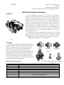
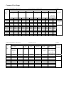
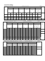
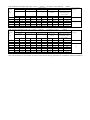
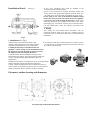
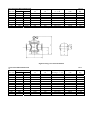
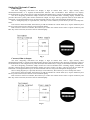
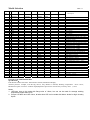
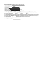
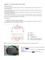
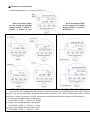
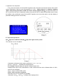
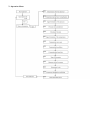
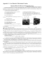
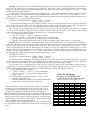
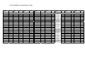
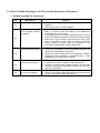
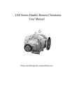
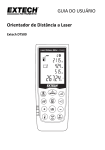
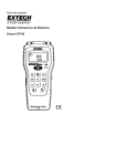
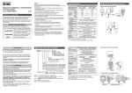
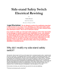
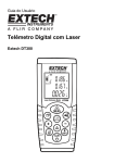
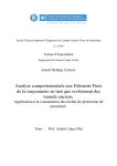
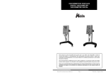
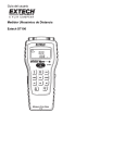
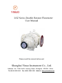
LSZ Series Double Rotator Flowmeter User Manual Please read this manual before use! Shanghai Yinuo Instrument Co., Ltd. Address: No. 7508 North Jiasong Road, Shanghai, 201804, China Tel:+86-21-3593 1213 Fax:+86-21-3593 1508 Website: www.yinuochina.com YINUO High quality volumetric-type instrument LSZ Double-Rotator Flowmeter Standard: Q/TCEP01-2003(LSZ Double-Rotator Flowmeter) LSZ Double-Rotator Flowmeter Summary LSZ Double-Rotator Flowmeter is the latest & international super-class volumetric-type flowmeter researched and developed by our company. It is a type of precise instrument measuring liquid flow in the pipeline, featuring high measurement precision, smooth running, free of pulsation, low noise, long service life and excellent adaptability to viscosity etc.. Therefore, it has been widely used in various fields such as petroleum, chemical, metallurgy, electric power, shipping, traffic, dock, mine, thermal power, and foodstuff industries etc.. It is especially suitable for commercial trade measurement for crude oil, high condensation oil, crude oil with high water content, petroleum products, foodstuff and chemical solutions as well as measuring management and control of engineering automation. The codes and characters displayed on the flowmeter can be directly read locally. The photo-electric pulse converter equipped can output electric pulse(current) signals to the displaying instrument and computer for handling. Thus, the flow in the pipeline can be remotely controlled. Patent No.: ZL 00216334.9 ZL 99250679.4 Fig. 1 Principle The measuring chamber of the double-rotator flowmeter consists of interior casing, a pair of helix rotators and top & bottom cover plates. These formed a cavity with known volume which can be used as the measuring unit for the flowmeter. The rotator of the flowmeter rotates under the tiny pressure difference between the inlet and outlet and continually sends the liquid at inlet to the outlet after cavity measurement(See Fig.2). The rotator transmits the rotating numbers to the counter by means of sealed coupling and driving system so that the total volume of the liquid passing the flowmeter can be directly displayed Main Technical Parameters Nominal Dia. (mm) Accuracy Pressure loss Nominal pressure Temperature range Media viscosity Ambient temperature Connected flange Photoelectric pulse(current)converter Electronic meterhead Table 1. 8~400 ±0.1%, ±0.2% and ±0.5% 0~1000mPa.s<80Kpa 1000~20000mPa.2<150KPa 1.6, 2.5, 4.0, 6.4 MPa -20°C ~ +80°C +80°C ~ +150°C +150°C ~ +250°C 0~20000mPa.s -40°C ~ +70°C Can be custom-made Exd II CT6(Excluding acetylene) Exd II CT2-T6 Common Flow Range LSZ Double-Rotator Flowmeter For Accuracy: 0.5% and 0.2% Table.2 Flow range m3/h Nominal 0.32-0.8mPa.s Dia. Gasoline/ liquefied (mm) gas 0.8-2mPa.s 2-5mPa.s Kerosene Pulse 2000-20000mPa.s equivalent Crude oil, heavy Hi-viscosity Liquid with high liter/pulse oil Liquid water content & 5-400mPa.s Light diesel 400-2000mPa.s super-high viscosity liquid 0.5% 0.2% 0.5% 0.2% 0.5% 0.4-4 0.2% 0.4-4 0.5% 0.2% 0.2% 0.2% 0.6-3 25 3-8 40 8-20 8-20 2.7-22 5.5-22 2.5-25 4.4-22 50 9-36 15-36 4.5-36 9-36 4-40 7.2-36 4-40 7.2-36 2.8-24 6-24 2.2-18 4.5-18 80 20-80 32-80 10-80 20-80 9-90 16-80 9-90 16-80 6.5-56 14-56 5-40 10-40 100 25-100 40-100 13-100 25-100 12-120 20-100 12-120 20-100 8.5-72 18-72 6.5-54 14-54 150 55-225 88-220 31-250 57-225 25-250 44-220 25-250 44-220 18-150 38-150 12-100 25-100 200 90-360 150-360 50-400 90-360 40-400 72-360 40-400 72-360 28-240 53-210 20-160 40-160 250 135-540 180-540 68-540 135-540 60-600 108-540 60-600 108-540 42-360 90-360 30-240 60-240 300 220-900 300-900 112-900 225-900 100-1000 180-900 100-1000 180-900 70-600 150-600 54-450 113-450 400 400-1600 550-1600 200-1600 400-1600 180-1800 320-1600 180-800 320-1600 130-1100 275-1100 90-750 180-750 1-10 LSZ Double-Rotator Flowmeter 0.3-2.4 0.5% 15 1.5-10 0.4-4 0.5% 1-10 0.3-2.4 1-8 2.5-25 4.4-22 0.001 1-6 2.1-18 4.2-18 1.5-12 Accuracy: 0.1% 0.32-2 mPa.s 2-5 mPa.s 5-50mPa.s 500-400 mPa.s Dia. (mm) Gasoline/ Kerosene Light diesel Crude oil, 0.1 Table.3 Flow range m3/h Nominal 0.01 3-12 heavy oil liquefied Pulse 400-2000 2000-20000 equivalent mPa.s mPa.s liter/pulse Hi-viscosity Liquid with high Liquid water content & super-high gas viscosity liquid 40 11-22 9-22 7.5-22 7.5-22 7.5-22 4-12 3.3-10 0.001 50 18-36 14.4-36 12-36 12-36 12-36 7.5-22 6-28 0.01 80 40-80 32-80 26.7-80 26.7-80 26.7-100 16-48 15-45 100 50-100 40-100 34-100 34-100 34-100 24-72 20-60 150 115-220 90-220 73-220 73-220 73-220 40-120 30-90 200 180-360 144-360 120-360 120-360 120-360 60-180 50-150 250 270-540 216-540 180-540 180-540 180-540 100-300 60-180 300 450-900 360-900 300-900 300-900 300-900 200-600 150-450 400 800-1600 640-1600 530-1600 530-1600 530-1600 400-1200 300-900 0.1 Special Flow Range LSZ -Electronic Meterhead Accuracy: 0.5%, 0.2% Table.4 Flow range m3/h Nominal 0.32-0.8mPa.s Dia. Gasoline/ (mm) liquefied gas 0.8-2mPa.s 2-5mPa.s Kerosene Pulse 400-2000mPa.s 2000-20000mPa.s equivalent Crude oil, heavy Hi-viscosity Liquid with high liter/pulse oil Liquid water content & 5-4mPa.s Light diesel super-high viscosity liquid 0.5 0.2 0.5 0.2 0.5 0.2 0.5 0.2 0.5 0.2 0.5 0.2 8 0.06-0.3 0.10-0.3 0.05-0.3 0.07-0.3 0.03-0.3 0.06-0.3 0.03-0.3 0.06-0.3 0.03-0.2 0.06-0.2 0.03-0.2 0.06-0.24 7 7 4 15A 0.2-0.8 0.27-0.8 0.1-0.8 0.2-0.8 0.08-0.8 0.16-0.8 0.08-.8 0.16-0.8 0.08-0.7 0.16-0.7 0.08-0.6 0.15-0.6 15B 0.25-1 0.33-1 0.2-1 0.25-1 0.1-1 0.2-1 0.1-1 0.2-1 0.1-0.9 0.2-0.9 0.1-0.8 0.2-0.8 25 1.5-6 1.2-6 1.2-6 1.5-6 0.6-6 1.2-6 0.6-6 1.2-6 0.5-5.4 1.2-5.4 0.6-5 1.2-5 LSZ -Stainless steel (-20°C ~ +80°C) Accuracy: 0.5% and 0.2% 0.32-0.8 mPa.s Dia. Gasoline/ (mm) liquefied gas 0.8-2 mPa.s 2-5 mPa.s Kerosene 0.1 Table.5 Flow range m3/h Nominal 0.01 Pulse 5-400 mPa.s 400-2000 mPa.s Light diesel, Crude oil, heavy Hi-viscosity diesel oil Liquid 2000-20000 mPa.s Liquid with high equivalent liter/pulse water content & super-high viscosity liquid 0.5 0.2 0.5 0.2 0.75-3 0.5 0.2 0.6-3 0.5 0.2 0.2 0.5 25 2-8 40 6-24 8-24 6-24 8-24 4.8-24 6-24 4.8-24 6-24 3.6-18 4-16 2.4-12 2.5-10 50 9-36 12-36 9-36 12-36 7.2-36 9-36 7.2-36 9-36 4.8-24 5.5-22 3.6-18 4-16 80 20-80 27-80 20-80 27-80 16-80 20-80 16-80 20-80 12-56 12-48 8-40 9-36 100 25-100 34-100 25-100 34-100 20-100 25-100 20-100 25-100 15-75 15-60 11-54 11-45 150 55-220 75-220 55-220 75-220 45-220 55-220 45-220 55-220 30-150 35-135 20-100 23-90 200 90-360 120-360 90-360 120-360 72-360 90-360 72-360 90-360 43-210 50-200 32-160 38-150 250 135-540 180-540 135-540 180-540 108-540 135-540 108-540 135-540 72-360 90-360 48-240 60-240 300 225-900 300-900 225-900 300-900 180-900 225-900 180-900 220-900 120-600 150-600 90-450 113-450 1.6-8 0.6-3 0.2 0.75-3 2-8 0.6-3 0.5 15 1.6-8 0.5-2.5 1.2-6 LSZ -Stainless steel high temp. type (+80°C ~ +150°C) 1-5 Accuracy: 0.5%, 0.2% 2-5 mPa.s Dia. Light diesel 5-50 mPa.s Crude oil, heavy oil 50-400 mPa.s Crude oil, heavy oil 0.2 0.5 0.2 0.5 0.2 0.1 Pulse equivalent 400-2000 mPa.s 2000-20000 mPa.s Hi-viscosity Liquid with high water content& Liquid super-high viscosity liquid (mm) 0.5 0.01 Table.6 Flow range m3/h Nominal 0.001 0.5 0.2 0.5 liter/pulse 0.2 40 5.6-22.5 7-20 5.6-22.5 7-20 5.6-22.5 7-20 4-15 4-12 3-12 3.5-10 50 9-36 10-32 9-36 10-32 9-36 10-32 4.5-22 7-20 4.5-18 6-18 80 20-80 25-75 20-80 25-75 20-80 25-75 12-48 13-40 9-36 10-30 100 25-100 30-90 25-100 30-90 25-100 30-90 15-60 17-50 11-45 14-40 150 45-220 75-220 45-220 75-220 45-220 75-220 35-135 34-100 23-90 27-80 200 90-360 120-360 90-360 120-360 90-360 120-360 50-200 54-160 38-150 43-130 250 135-540 180-540 135-540 180-540 135-540 180-540 90-360 120-360 60-240 80-240 300 225-900 300-900 225-900 300-900 225-900 300-900 150-600 200-600 113-450 150-450 0.01 0.1 LSZ -Stainless steel high temp. type (+150°C ~ +250°C) Accuracy: 0.5% and 0.2% Table.7 Flow range m3/h Nominal Dia. (mm) 2-5 mPa.s 40 7.5-22.5 10-20 7.5-22.5 10-20 7.5-22.5 10-20 5-15 6-12 4-12 5-10 50 12-36 16-32 12-36 16-32 12-36 16-32 7.5-22.5 10-20 6-18 9-18 5-50 Light diesel 0.5 0.2 mPa.s 50-400 Crude oil, heavy oil 0.5 0.2 mPa.s Crude oil, heavy oil 0.5 0.2 400-2000 mPa.s Hi-viscosity Liquid 0.5 0.2 2000-20000 mPa.s Liquid with high water content& super-high viscosity liquid 0.5 0.2 80 26.7-80 35-75 26.7-80 35-75 26.7-80 35-75 16-48 20-40 12-36 15-30 100 34-100 45-90 34-100 45-90 34-100 45-90 20-60 25-50 15-45 20-40 150 75-220 110-220 75-220 110-220 75-220 110-220 45-135 50-100 30-90 40-80 200 120-360 180-360 120-360 180-360 120-360 180-360 65-200 80-160 50-150 65-130 LSZ -Carbon steel high temp. type (+150°C ~ +250°C) Accuracy: 0.5, 0.2 Nominal Dia. (mm) 2-5 mPa.s 0.5 0.2 0.5 0.2 0.5 0.2 40 4.5-22.5 5.6-22.5 4.5-22.5 5.6-22.5 4.5-22.5 5.6-22.5 4.2-18 5-15 3-12 50 7.2-36 9-36 7.2-36 9-36 7.2-36 9-36 6-24 7.5-22.5 4.5-18 80 16-80 20-80 16-80 20-80 16-80 20-80 14-56 16-48 10-40 12-36 100 20-100 25-100 20-100 25-100 20-100 25-100 18-72 20-60 14-54 16-48 150 45-220 55-220 45-220 55-220 45-220 55-220 38-150 45-135 25-100 30-90 200 72-360 90-360 72-360 90-360 72-360 90-360 53-210 65-200 40-160 50-150 250 108-540 135-540 108-540 135-540 108-540 135-540 72-360 90-360 60-240 80-240 300 180-900 225-900 180-900 225-900 180-900 225-900 120-600 150-600 113-450 150-450 Light diesel mPa.s 50-400 Crude oil, heavy oil mPa.s Crude oil, heavy oil 400-2000 mPa.s Hi-viscosity Liquid 0.5 0.2 0.01 0.1 Table.8 Flow range m3/h 5-50 Pulse equivalent liter/pulse 2000-20000 mPa.s Pulse equivalent liter/pulse Liquid with high water content& super-high viscosity liquid 0.5 0.2 4-12 0.01 5.5-17.5 0.1 Note: The flowmeter is also suitable for interim measurement during installation/un installation and ship installation. Installation Sketch See Fig. 4 f. The valve regulating flow shall be installed at the downstream side of the flowmeter. g. If it is not convenient to read the flowmeter locally, the fixing screw of the gauge outfit shall be removed. Then, turn the outfit to the convenient side and tighten the screw again. h. The front & rear valve of the flowmeter shall be closed before the water pressure test is done for the new pipeline to prevent water from entering the flowmeter. If the water enters the flowmeter, the remained water and air after water discharging may corrode the internal parts of the flowmeter, rust the rotation parts, affect the precision and shorten the service life. 2. Wiring The wiring for LSZ double-rotator flowmeter with Ex transmitter shall be done as per the user’s manual of the Ex transmitter. The Ex transmitter shall not be damaged during installation. Fig.4 1. Installation See Fig.4 a.The position of the flowmeter shall avoid 3. Avoid using crude oil to test the flowmeter. If crude oil must vibration, high temperature and strong magnetic be used for test, it shall be exhausted when hot after test from disturbance and shall be easy for maintenance. the outlet of the flowmeter. b. When the flowmeter is installed on the new pipeline, a section of pipe can be installed instead of the flowmeter for pipe cleaning in order to prevent the impurity from entering the flowmeter. c. The flowmeter shall be installed vertically on the horizontal main pipeline. The bypass pipeline shall refer to Fig.4. The horizontal piping shall leave space for maintenance. d. While the flowmeter is installed, the arrow on the flowmeter shall be identical with the liquid flowing direction. e. Filter shall be installed at the front of flowmeter inlet. In order to make the measurement precise, the air in the pipeline shall be exhausted. Hence, exhauster shall be installed. Flowmeter outline drawing and dimension Fig.6 Drawing of Horizontal installation Horizontal installation dimension Nominal Flange space L Total height Center height Install hole space Dia. mm Standard Special H M A × B 8 82* 180/150 260 35 15 180 200 300 55 25 200 250 350 80 40 250 300 500 130 50 360 378 580 140 80 400 380 700 230 100 450 500** 700 260 250×220 150 560 650** 800 290 250×270 * Connection to be conical tube thread 1/8” ** Nominal pressure is 6.4MPa. Bolt hole size n-Φ 4-Φ20 4-Φ20 Table 9 Mass Kg 5 10 15 40 70 140 180 320 Fig.6 Drawing of Vertical installation Vertical installation dimension 10 Nominal Flange space L Dia. mm Standard Special 8 82* 180/150 15 180 200 25 200 250 40 250 300 50 360 378 80 400 380 100 450 500 150 560 650 200 700 250 1000 300 1000 400 1200 Table Total height H 210 260 300 500 580 700 780 828 1180 1210 1460 1700 Center height M 50 50 68 126 150 222 270 318 450 500 640 700 Install hole space Footing A × B Bolt hole size n-Φ 340×215 450×240 445×200 524×250 645×300 700×300 4-Φ23 4-Φ23 4-Φ23 4-Φ25 4-Φ25 8-Φ25 Mass Kg 7 8 15 40 60 120 150 300 560 1000 1460 2000 Installation, Maintenance and Commissioning of LSZ Series Double Rotator Flowmeter Ⅰ. Installation Location (1) The flowmeter should be installed in the dry, ventilated location where there are less corrosive gas, no vibration and good waterproof measurement. (2) The proper location should be made sure and the attention should be paid to the expansion and contraction of the main pipeline when the flowmeter is installed so as to avoid the flowmeter will deform and vibrate because of the improper installation under the outside force, which will influences the measurement accuracy. (3) The flowmeter should be installed horizontally or vertically according to the regulation. The measured liquid should run through the flowmeter from the bottom up so that the tube of the flowmeter will be full of liquid or not bring about air bubble. (4) The installation location should be easy to read. The installation of flowmeter and display instrument should be avoid the interference of the strong alternating or direct current magnetic field so that the system and external electric will be separated effectively. Ⅱ Installation Requirement The pipeline should be cleaned thoroughly, avoiding that the impurity enter the flowmeter and cause the flowmeter blocked or damaged. When installed in the new pipe, a piece of short pipe with flanges should be substituted for flowmeter for a while so that the impurity will be eliminated before installing the flowmeter. If there is the bypass pipeline, the liquid with impurity should passed through the bypass pipeline. In order to avoid that the display instrument is disturbed by electromagnetic induction, static and capacitive coupling etc., the attention should be paid to the following situations: (1) Restrict the length of cable between transmitter, transducer and display instrument; (2) Signal cable should be adopted the metal shielded wire and be grounded reliably; (3) The cable and tube should not be near to wiring or parallelized with power line. Explosion proof instrument should be inspected if there is explosion proof marks on the crust before installed. For example, if the instrument has explosion proof structure, check the perfection of sealing arrangement, the sealing of cable outlet, rubber airproof washer, wiring box, switch and wiring according to the Explosion Proof Requirements. Ⅲ Operation, Maintenance and Management The following notes should be paid attention to during the maintenance and management: (1) The flowmeter should be used according to the stated flow range, working pressure and working temperature so as to ensure the measuring accuracy and lifetime. (2) The measured liquid must be adapted to the material of the body and other parts to avoid that the damage of the flowmeter when the flowmeter touches the corrosive liquid. (3) The outlet valve should be close before the flowmeter works. Make liquid full of the pipe and flowmeter, then open the outlet valve and check if it is all right. Setting for Electronic Counter Pulse output The flow integrating instrument can display 4 digit of instant flow, with 1 digit accuracy after decimal(0-999.9m3/h) or 2 digits(0-99.99m3/h)after decimal. The accumulative flow function can display accumulated flow, with 4 digit accuracy after decimal(0-9999.9999m3/h) or 5 digit (0-999.99999m3/h) after decimal. The flow integrating instrument adopts instant flow and accumulated flow switching display methods and provides three-wire system pulse remote transmission output, see Fig.4. All key operation must be done while the instrument is running(With flow input). Or the instrument will be in low-power dissipation sleeping status. SET is setting key(Only it is pressed first, other keys can be effective); Press this key to set or modify flow factor. INC means to add one number; Press this key to add one number for current factor (0-9). If press FA/SL key and INC key at the same time, the factors can be increased rapidly. DEC means to reduce one number; Press this key to reduce one number for the factor. If press FA/SL key and DEC key at the same time, the factors can be reduced rapidly. Fig. 7 Current(4-20mA) Output The flow integrating instrument can display 4 digit of instant flow, with 1 digit accuracy after decimal(0-999.9m3/h) or 2 digits(0-99.99m3/h)after decimal. The accumulative flow function can display 8 digit of accumulated flow, with 4 digit accuracy after decimal(0-9999.9999m3/h) or 5 digit (0-999.99999m3/h) after decimal. The flow integrating instrument adopts instant flow and accumulated flow switching display methods and provides 4-20mA current remote transmission output (two-wire system), see Fig.5. All keys must be set while the instrument is running(With flow input). Or the instrument will be in low-power dissipation sleeping status. SET is setting key(Only it is pressed, other keys can be effective); Press this key to set or modify flow factor. INC means to add one number; Press this key to add one number for current factor (0-9). If press FA/SL key and INC key at the same time, the factors can be increased rapidly. DEC means to reduce one number; Press this key to reduce one number for the factor. If press FA/SL key and DEC key at the same time, the factors can be reduced rapidly. Fig. 8 Model Selection Basic type LSZ Table 11 - 1 2 3 4 5 6 7 8 - Nominal Diameter 8 15A 15B 25 40 50 80 100 150 200 250 300 400 Counter Nominal pressure Feature Material Quality Work Temp. Transmitter Accuracy Description T J D M M1 1.6 2.5 4.0 6.4 P Q G S304 S316 SS304 SS316 A B C F I F1 I1 0.5 0.2 0.1 Double-rotator flowmeter DN: 8mm DN: 15mm Type A DN: 15mm Type B DN: 25mm DN: 40mm DN: 50mm DN: 80mm DN: 100mm DN: 150mm DN: 200mm DN: 300mm DN: 400mm Pulse transmitter without local display Mechanical counter without zero-reset Electronic counter Zero-reset Mechanical counter Square large digit Mechanical counter Nominal pressure: 1.6MPa Nominal pressure: 2.5MPa Nominal pressure: 4.0MPa Nominal pressure: 6.4MPa Basic specification Special for gasoline & liquefied gas Common type Only Rotator is SS304 Only Rotator is SS316 Body & Rotator: SS304 Body & Rotator: SS316 Work temperature: -20°C ~ +80°C Work temperature:+80°C ~ +150°C Work temperature:+150°C ~ +250°C Photoelectric converter: pulse output Photoelectric converter: current output Electronic counter: pulse output Electronic counter: current output Accuracy:±0.5% Accuracy: ±0.2% Accuracy: ±0.1% Example: LSZ-100J2.5ZS304AI0.2 Specifications: LSZ Double-rotator flowmeter: Nominal dia. 100mm; Mechanical display; nominal pressure: 2.5Mpa, with driving device; only Rotator is SS304; Working temperature: -20°C~+80°C; Photoelectric pulse converter: 4-20mA output(Explosion-proof class: Exd II CT6); Accuracy class: ±0.2%. Notes: 1. LSZ-8mm have to be made with flange size of 15mm, but can not be used for average working temperature higher than 80°C! 2. Except LSZ-8mm and LSZ-15mm, all other size LSZ can be made with Warm Jacket for high viscosity liquid! Please pay attention to following contents when ordering: The flowmeter Model: 1. Nominal diameter: DN mm. 2. Working temperature: °C. 3. Transmitter: ; 5. Name of fluid: ; 6. Density of fluid: g/cm3; 7. Viscosity of fluid: 8. Range of flow: Max; Normal , Min.m3/h; 9. Counter: Pulse transmitter without gauge outfit Mechanical counter Electronic counter Zero-reset mechanical counter Large code counter imported large code counter; 10. Pressure of fluid: Max. Normal Lowest MPa; 11. Feature: Basic specification Gasoline and liquefied gas Driving device Mechanical sealing 12. Material quality: Rotator 304 Rotator 316 Rotator and casing 304 Rotator and casing 316; 13. Flange standard: Flush welding concave convexity 14. Way of Installation: Horizontal Vertical 15. Companion filter type: . Appendix: User Manual of Electronic Counter I. Brief Introduction This manual is applied for updated electronic counter of LSZ Series Double Rotator flowmeter, which has the following features: 1. It can display only the instantaneous flow and total flow but also the batch total flow. Among them, batch total flow can be reset to zero. 2. High precise correction curve has been embedded into the electronic counter to ensure the accuracy of measurement of the flowmeter. 3. Pulse output (powered by DC24V±5%, VH≥20V, VL<1V and output load <200Ω), 4-20mA output (two wire system and resolution is 1/65536) and RS485 communication with Modbus/RTU (powered by DC24V±5% and <60mA) are optional for various choice. II. Connection: The wiring type of electronic-counter is as follows: Function with pulse, 4-20mA and RS485 together (shown in drawing) but it is necessary to require two separate DC24V for connection of pulse and 4-20mA. 1 (+):DC24V+; 2 (P):Pulse output; 3 (-): DC24V-; 4 (I+) 4~20mA output ”+” 5 (I-): 4~20mA output ”-” 6 (A): RS485 communication output A; 7 (B): RS485 communication output B; Note: If there are lines extended from electronic counter, please refer to the meanings as follows: Pulse output lines: 24V+(Red), 24V-(Blue) and Pulse signal line(Yellow); 4-20mA output lines: 24V+(Red) and Current signal line(Blue); RS485 output lines: A line(Yellow) and B line(Green). Ⅲ. Parameters and Operation 1. Keyboard and Display(as shown in the picture 1) Press the button of INC to inter-change the displays among Picture 1, Picture 2, Picture 3, Picture 4 and Press the button of DEC to inter-change the displays among Picture 1, Picture 6 and Picture 7. Note: “TF or Total Flow” in above pictures do not means the totalizer (Total Flow Value)!!! The total flow value (totalizer) of liquid flowmeters should be calculated by combining high section with low section because it can not be read directly. Supposed TOTALIZER is total flow value, Total_H means High section of TOTAL while Total_L means Low section of TOTAL, and there are three situations as follows (shown in Pictures 6 and 7): 1). If there are three digits decimal of High section, TOTALIZER=TOTAL_L+TOTAL_H×100000; 2). If there are four digits decimal of High section, TOTALIZER=TOTAL_L+TOTAL_H×10000; 3). If there are five digits decimal of High section, TOTALIZER=TOTAL_L+TOTAL_H×1000. 2. Operation of the keyboard First, press the buttons of FUN and SET together at the some time and Picture 8 will be shown (PRT means Parameters). Second, input the password of “5136” (When picture 8 is showing, inputting “8057” and pressing the button of SET will restore factory default setting.)and press the button of SET to enter into the menu of parameter setting, now press the SET to select the parameter which should be modified. After modification, press FUN and SET together at the some time again to exit the display of parameter setting;(as shown in the chart) How to move the cursor INC: increase one DEC: decrease one FUN and INC: toward left FUN and DEC: toward right IV. Functional parameter. K[1]~K[5]: flow coefficient and K[6]~K[10]: flow signal section points. The correction curve is as bellow: Calculation of flowrate section points coefficients, i.e.: Kx(x=[6~10]): K[x-5]new=K[X-5]old ×(standard flow/ displayed flow) For example: Suppose K[6]=100 relevant coefficient K[1]=1223 Displayed flow value of the Tested Meter is 1500L while actual flow value of Master Meter is 1523L, then the new coefficient: K[1]new=K[1] old×1523L/1500L=1242 K[11]:linear correction coefficient Move the whole curve integrally and parallelly. Calculation: K[11]new=K[11] old×(standard flow/ displayed flow) For Example: K[11] old=1100, the displayed flow value in the course of the calibration is 1300L while the actual flow value is 1345L, then K[11] new=1100×1345/1300=1138. K[12]option of the instantaneous flowrate decimal: K[12]=0 instantaneous flowrate without decimal; K[12]=1 instantaneous flowrate with one decimal; K[12]=2 instantaneous flowrate with two decimal; K[12]≥3 instantaneous flowrate with one decimal. K[13] option of temperature and pressure compensation: K[13]=0 no pressure and temperature compensation; K[13]=1 pressure and temperature compensation; K[13]>1 no pressure and temperature compensation. K[14] upper limitation of the pressure: Upper limitation of the pressure sensor's range K[15] pressure zero-amendment: Zero point amendment value of the pressure sensor K[16] maximum flowrate: The relevant instantaneous flowrate of 20mA under 4~20mA output K[17] upper limitation of the temperature: Upper limitation of the temperature sensor's range, which has been set before delivery K[18] temperature zero-reset: Zero point amendment value of the temperature sensor, which has been set before delivery K[19]communication address: RS232/R485 communication address range 0~255 K[20]communication baud rate: K[20]=0 frequency=1200; K[20]=1 frequency=2400; K[20]=2 frequency=4800; K[20]=3 frequency=9600; K[20]>3 frequency=9600 K[21] type of the flowmeter K[21]=0 for liquid; K[21]=1 for gas; K[21]≥2 for liquid K[22] diameter of the flowmeter: Input the flowmeter's nominal diameter directly with unit of mm K[23] flowmeter's unit: K[23]=0 Cubic meter(m3); K[23]=1 Liter(L); K[23]=2 Ton(T); K[23]=3 Kilogram(Kg); K[23]=4 US. Gallon(G); K[23]≥4 Cubic meter(m3) K[24] frequency distribution coefficient: Reserved by factory K[25] option of pulse equivalent(L/P): K[25]=0 pulse equivalent=10; K[25]=1 pulse equivalent=1; K[25]=2 pulse equivalent=0.1; K[25]=3 pulse equivalent=0.01; K[25]=4 pulse equivalent=0.001 V. Operation Menu VI. Certificates Appendix 2 : User Manual of Mechanical Counter Adjustment Method for Mechanical Flowmeter Error Curve ---- Mechanical small gauge outfit gear adjustment Normally, the manufacturer of volumetric flowmeter(Hereinafter called: flowmeter) uses fluid like: diesel, machine oil or water to verify the flowmeter. However, the liquids actually used by users vary greatly. The actual fluid viscosity often has big difference with the one when it is verified. This caused the deviation for error curve of the flowmeter. Therefore, it is necessary to correct the error curve of the flowmeter. 1. LSZ-40~300 error adjustment method z Gear adjusting mechanism see Fig. 9, in which: No.1 is adjusting plate fixing screw No.2 is adjusting gear1(Z: 44/42) No.3 is output gear(Z: 25) No.4 is carrier gear(Z: 27) The big gear(Z:48) of adjusting gear 2(No.5) is installed z Adjusting gear installation see Fig.10. Loosen 4 fixing screws(No.1); move adjusting gear 1/2. Loosen lock screw(No.6) to remove adjusting screw 1/2. Note: The small gear(Z:42) of adjusting gear 1(No.2) is installed towards the interior. towards the interior. No.5 is adjusting gear 2(Z: 48/46) No.6 is adjusting gear lock screw No.7 is input gear(Z: 44) No.8 is gear installation bottom plate No.9 is adjusting plate. Look up table 12: Adjusting gear is at +0.54 position. The direction of big & small gear must be correct while installation. Fig. 9 Fig.10 zError curve adjustment method: Example 1: The accuracy of LSZ-80 double-rotator flowmeter is class 0.2 when ex-factory. When the verification is done at site, the change (or other cause) of the fluid which verifies the flowmeter caused the deviation of flowmeter error curve. The verification result at site showed that the error of the flowmeter is –0.4 ~ –0.7%, which exceeded the range of class 0.2. Look up table at site. The gear combination for adjusting gear 1 is 44/42 and the gear combination for adjusting gear 2 is 48/46(Note: The gear number of two groups of adjusting gears as well as the position of error adjustment table are printed on the certificate of the flowmeter.). Look up table 12. The position of two groups of adjusting gears is at +0.54%. The error of the flowmeter is –0.4 ~ –0.7%. Its max. linearity is 0.3%. Adjust the linearity based on the half of the 0.3% linearity and adjust the flowmeter to the position of +0.15 ~ –0.15%. The adjusting method is: The linear error adjusting amount: +0.15%~(–0.4%) = +0.55% or -0.15%~(–0.7%) = +0.55% or i.e: The amount to be adjusted for the flowmeter shall be +0.55%. The original position of the two groups of adjusting gears +0.54% plus +0.55% which need to be adjusted. The new position of the two groups of adjusting gears shall be at +1.09%. Look up table 1: The adjusting gear at +1.09% position is 51/49 and 47/45. When the two groups of adjusting gears 51/49 and 47/45 are installed, the gaps between the gears shall not be too large and the gears shall not be too tight. The joggles between the gears shall have a certain space. Thus, the error of the flowmeter has been adjusted. Example 2: The accuracy of LSZ-100 Double-Rotator Flowmeter is class 0.2 when ex-factory. When the verification is done at site, the change (or other cause)of the fluid which verifies the flowmeter caused the deviation of flowmeter error curve. The verification result at site showed that the error of the flowmeter is +0.35 ~ +0.7%, which exceeded the range of class 0.2. Look up table at site. The gear combination for adjusting gear 1 is 44/42 and the gear combination for adjusting gear 2 is 48/46. The error of the flowmeter is +0.35 ~ +0.7%. Its max. linearity is 0.35%. Adjust the linearity based on the half of the 0.35% linearity and adjust the flowmeter to the position of +0.175 ~ –0.175%. The adjusting method is: The linear error adjusting amount: +0.175%-(+0.7%) = +0.525% -0.175%-(+0.35%) = +0.525% i.e: The amount to be adjusted for the flowmeter shall be +0.525%. The original position of the two groups of adjusting gears +0.54% plus +0.525% which need to be adjusted, the new position of the two groups of adjusting gears shall be at +0.015%. Look up table 12: There is no +0.015% adjusting gear. So, select the gear position +0.02% which is the nearest position for +0.015%. The adjusting gear shall be 49/47 and 39/37. Example 3: The accuracy of LSZ-100 Double-Rotator Flowmeter is class 0.2 when ex-factory. When the verification is done at site, the great change of the fluid (such as gasoline or other cause) which verifies the flowmeter caused the great deviation of flowmeter error curve. The verification result at site showed that the error of the flowmeter is +0.85% ~ +2.25%, which exceeded the range of class 0.2. Look up table at site. The gear combination for adjusting gear 1 is 44/42 and the gear combination for adjusting gear 2 is 48/46. Look up table 12. The position of two group of adjusting gears is at +0.54%. The error of the flowmeter is –1.85 ~ -2.25%. Its max. linearity is 0.40%. Adjust the linearity based on the half of the 0.40% linearity and adjust the flowmeter to the position of +0.2 ~ –0.2%. The adjusting method is: The linear error adjusting amount: +0.20%-(-1.85%) = +2.05% or -0.20%-(-2.25%) = +2.05% i.e: The amount to be adjusted for the flowmeter shall be +2.05%. The original position of the two groups of adjusting gears +0.54% plus +2.05% which need to be adjusted. The new position of the two groups of adjusting gears shall be at +2.59%. Look up table 12: There is no +2.59% adjusting gear and it has exceeded the range in Table 1. Here, the only way is to change the input gear (No.7Z=44) to (Z=43). If the tooth number of the input gear is changed from 44 to 43, the adjusting amount is +2.27‰, which exceeded the adjusting amount of +2.05%. Every 1 tooth number reduced for input gear, the adjusting amount will increase 2.27%. The adjusting method is: a. First, change 44 teeth to 43 teeth; b. +2.27% - (+2.05%) = + 0.22% (+ 0.22% more adjusted) c. +0.54% - (+0.22%) = + 0.32% (the new position of two groups of gears) d. Look up table 1: the adjusting gear at + 0.32% position is 51/49 and 40/38. e. Example 3 shall change output gear 44 teeth to 43 teeth, and adjusting gear (49/46, 44/42) to (51/49, 40/38). Example 4: The accuracy of LSZ-100 Double-Rotator Flowmeter is class 0.2 when ex-factory. When the verification is done at site, the great change of the fluid (such as gasoline or other cause) which verifies the flowmeter caused the great deviation of flowmeter error curve. The verification result at site showed that the error of the flowmeter is +0.85% ~ +2.25%, which exceeded the range of class 0.2. After looking up the table at site, the gear combination for adjusting gear 1 is 44/42 and the gear combination for adjusting gear 2 is 48/46. Look up table 12: The position for two groups of adjusting gears is at +0.54%. The error of the flowmeter is –1.85 ~ -2.25%. Its max. linearity is 0.40%. Adjust the linearity based on the half of the 0.40% linearity and adjust the flowmeter to the position of +0.2 ~ –0.2%. The adjusting method is: The linear error adjusting amount: +0.20%-(-1.85%) = +2.05% or -0.20%-(-2.25%) = +2.05% i.e: The amount to be adjusted for the flowmeter shall be +2.05%. The original position for the two groups of adjusting gears +0.54% plus +2.05% which need to be adjusted. The new position for the two groups of adjusting gears shall be at +2.59%. Look up table 12: There is no +2.59% adjusting gear and it has exceeded the range in Table 1. Here, the only way is to change the input gear (very few Z=45) into (Z=44). If the tooth number of the input gear is changed from 45 to 44, the adjusting amount is +2.22%, which exceeded the adjusting amount of +2.05%. Every 1 tooth number reduced for output/input gear, the adjusting amount will increase 2.22%. The adjusting method is: a. First, change 45 teeth to 44 teeth; b. +2.22% - (+2.05%) = + 0.17% (+ 0.17% more adjusted) c. +0.54% - (+0.22%) = + 0.37% (the new position of two Notes for Ordering: groups of gears) d. Look up table 1: the adjusting gear at + 0.32% (+0.36%) Flowmeter error adjustment table position is 50/48 and 41/39. 1. LSZ-15, 25 error adjusting gear table e. Example 4 shall change output gear 45 teeth to 44 teeth, and 39/41 +1.60 25/27 +4.21 43/44 –1.10 adjusting gear (48/46, 44/42) to (50/48, 41/39). ………………… 39/41 +1.60 25/27 +4.21 43/44 -1.10 40/42 +1.47 26/28 +3.94 42/43 -1.04 41/43 +1.36 27/29 +3.70 41/42 -0.98 zIf the flowmeter is found running too fast through site verification, 42/44 +1.25 28/30 +3.50 40/41 -0.93 the input gear can be changed from (Z=43) to (Z=44). Thus, every 43/45 +1.15 29/31 +3.20 39/40 -0.86 1 tooth increases, the adjusting amount will reduce 2.33%. The error 44/46 +1.05 30/32 +3.00 38/39 -0.80 calculation and adjustment methods are the same as Example 2. 45/47 +0.96 21/33 +2.82 37/38 -0.73 zWhen calculating the adjusting amount for adjusting gear, the adjusting 46/48 +0.86 32/34 +2.64 36/37 -0.65 direction shall be noticed. If the flowmeter runs faster(i.e: positive error), 47/49 +0.77 33/35 +2.52 35/36 -0.57 24/25 +0.69 34/36 +2.35 34/35 -0.49 adjust towards negative(“minus” adjusting amount at original position); If the flowmeter runs slower(i.e: negative error), adjust towards positive 25/26 +0.53 35/37 +2.19 33/34 -0.41 26/27 +0.38 36/38 +2.04 32/33 -0.32 (“Plus” adjusting amount at original position) zIf any problems are met during flowmeter error curve adjustment (As 27/28 +0.25 37/39 +1.89 31/32 -0.22 28/29 +0.13 38/40 +1.89 30/31 -0.11 per the methods in this manual)at site, please contact our company right 29/30 0 29/30 away. 2. LSZ-40-300 Error Adiusting Gear Table Adjust Gear 46/44 41/39 49/47 39/37 51/49 38/36 48/46 40/38 47/45 41/39 46/44 42/40 49/47 40/38 51/49 39/37 48/46 41/39 41/45 42/40 46/44 43/41 49/47 41/39 48/46 42/40 51/49 40/38 46/44 44/42 50/48 41/39 49/47 42/40 48/46 43/41 51/49 41/39 46/44 45/43 50/48 42/40 49/47 43/41 48/46 44/42 Error Adjust Gear +0.02 +0.01 +0.06 +0.10 +0.12 +0.15 +0.18 +0.19 +0.22 +0.24 +0.20 +0.31 +0.32 +0.35 +0.36 +0.40 +0.42 +0.44 +0.45 +0.48 +0.52 +0.54 51/49 42/40 50/48 43/41 49/47 44/42 48/46 45/43 46/44 47/45 51/49 43/41 50/48 44/42 49/47 45/43 52/50 43/41 51/49 44/42 50/48 45/43 48/47 46/44 52/50 44/42 51/49 45/43 50/48 46/44 48/46 48/46 53/51 44/42 52/50 45/43 51/49 46/44 49/47 48/46 43/51 45/43 52/50 46/44 Error 0% +0.57 +0.60 +0.62 +0.64 +0.65 +0.68 +0.71 +0.73 +0.76 +0.79 +0.81 +0.83 +0.87 +0.89 +0.92 +0.93 +0.94 +1.00 +1.02 +1.05 +1.07 Adjust Gear Error 51/49 47/45 49/47 49/47 53/51 46/44 52/50 46/45 51/49 47/46 50/48 48/47 53/51 49/45 52/50 47/46 51/49 48/47 53/51 49/46 52/50 48/47 51/49 50/48 53/51 49/47 51/49 51/49 52/50 51/ 49 852/50 52/50 52/50 53/51 53/51 53/51 +1.09 +1.11 +1.15 +1.15 +1.17 +1.18 +1.19 +1.24 +1.26 +1.27 +1.35 +1.35 +1.42 +1.44 +1.51 +1.59 +1.66 +1.74 Adjust Gear 46/44 41/39 47/45 40/38 50/48 38/36 49/46 39/37 45/43 41/39 46/44 40/38 47/46 39/37 52/50 36/34 44/42 41/39 45/43 40/38 46/44 39/37 49/47 37/35 47/45 38/36 50/48 36/34 48/46 37/35 46/44 38/36 43/41 40/38 42/40 39/37 45/43 38/36 48/46 36/34 46/44 37/35 43/41 39/37 47/45 36/34 45/43 37/35 Error Adjust Gear Error -0.03 -0.04 -0.07 -0.10 -0.13 -0.17 -0.19 -0.21 -0.23 -0.26 -0.28 -0.31 -0.35 -0.37 -0.41 -0.45 -0.47 -0.51 -0.53 -0.56 -0.58 -0.62 -0.66 40/38 41/39 46/44 36/34 52/50 33/31 44/42 37/35 47/45 35/33 39/37 41/39 42/40 28/26 48/46 34/32 46/44 35/33 44/42 36/34 52/50 32/30 40/38 39/37 38/36 41/39 42/40 37/35 51/49 32/30 43/41 36/34 46/44 34/32 44/42 35/33 37/35 41/35 52/50 31/29 47/45 33/31 49/47 32/30 51/49 31/29 -0.69 -0.71 -0.73 -0.77 -0.79 -0.82 -0.84 -0.88 -0.89 -0.93 -0.93 -0.95 -0.97 -1.00 -1.01 -1.04 -1.07 -1.10 -1.12 -1.15 -1.16 -1.18 -1.23 Adjust Gear Error 48/46 32/30 41/39 36/34 50/48 31/29 47/45 32/30 49/47 31/29 40/38 36/34 46/44 32/30 48/46 31/29 38/36 37/35 39/37 36/34 43/41 33/31 0% -1.27 -1.28 -1.31 -1.36 -1.40 -1.41 -1.46 -1.49 -1.53 -1.55 -1.58 46/44 47/44 43/41 19/46 44/42 48/45 45/43 47/44 48/46 45/42 46/44 46/43 43/41 48/45 44/42 47/44 45/44 46/43 41/39 49/46 43/41 47/44 1.61-1.65 -1.67 -1.71 -1.72 -1.76 -1.79 -1.82 -1.86 -1.89 -1.93 Adjust Gear Error Adjust Gear Error 44/42 46/43 41/45 44/41 40/38 49/46 42/40 47/44 43/41 46/43 44/42 45/42 39/37 49/46 42/40 46/43 43/41 45/42 46/44 43/40 44/42 44/41 39/37 48/45 41/39 46/43 42/40 45/42 43/41 44/41 38/36 48/45 37/35 49/46 41/39 45/45 42/40 44/42 45/43 42/49 38/36 47/44 37/35 48/45 41/39 44/41 -1.79 -1.98 -2.02 -2.05 -2.08 -2.13 -2.16 -2.20 -2.24 -2.26 -2.29 -2.30 -2.33 -2.36 -2.41 -2.44 -2.46 -2.48 -2.53 -2.54 -2.59 -2.60 -2.65 42/40 43/40 38/45 46/43 36/34 48/45 35/33 49/46 41/39 43/40 34/32 50/47 42/40 42/39 37/35 46/43 35/33 48/45 40/38 43/40 34/43 49/46 41/39 42/39 33/31 50/47 36/34 46/43 38/36 44/41 39/37 43/40 34/32 48/45 40/38 42/39 33/31 49/46 37/35 44/41 32/30 50/47 34/32 47/44 33/31 48/45 -2.70 -2.74 -2.76 -2.79 -2.83 -2.84 -2.88 -2.90 -2.93 -2.96 -2.98 -3.01 -3.04 -3.06 -3.07 -2.10 -3.12 -3.14 -3.17 -3.22 -3.25 -3.26 -3.31 V. FAQ & Trouble Shooting for LSZ Series Double Rotator Flowmeter 1. Trouble shooting for electronics: No. Description No display Method 01 1. Renew the battery and check if the voltage <3V. If so replace it 2. check the circuit if it's short-circuited 02 There is flow in the pipe 1. To check if the flowmeter is blocked. If so, take it down to but the display value is clean. If no block, check the settings of the parameters unchanged. according to the user manual. 2. If the parameters are correct, disassemble the counter, connect the signal input part of counter with another signal source (VH-H≤5V) to check if the counter can work. If yes, there is something wrong with the sensor, otherwise, contact factory for repair. Note: pay attention to the connection of signal line’s cathode and anode. No pulse output or inaccurate signal output. 1. Check the wiring according to the illustration in II. 2. Check the compatibility of pulse equivalent between the flowmeter and secondary instrument. 3. Check the pulse frequencies and amplitudes between flowmeter and secondary instrument/system using oscillograph to confirm they are suited. No 4-20mA output or no precise 4-20mA output 1. Check the wiring according to the illustration in II. If the connection is incorrect, please contact the factory. 2. If there is current output, please check if the set max. flowrate in secondary instrument or system is same with that of the flowmeter. 1. Check the wiring according to the illustration in II. 2. Check if it's powered with 24V battery and if the wiring is correct. If so, please contact the factory. 03 04 05 RS485 communication can no be connected. 2. Trouble shooting for Mechanical parts: Trouble Cause Solution (1) the measured liquid fails to pass through the flowmeter, and the meter head fails to count. (2) the noise is loud when the flowmeter works, and the accuracy is influenced gradually. (1) filter has been jammed (2) the foreign matter has entered measuring chamber(e.g.: welding rod, wire, plastic, stone),causes the rotator blocked (1) bearing attrition (2) the thrust bearing wears out, and the rotator shaft sinks so that the rotator end surface scratches mutually with the up and down cover boards (3) the sealing part is leaking (4) the meter head does not count, but the rotor shaft runs well and the fluid discharges as usual the airproof washer gets older and expired (1) the gear pin ruptures or falls off (2) the major axis of the alnico connecting mechanism breaks off (3) the gear and the axis of the shift gear mechanism are blocked. (4) the cross connecting rod of the shift gear mechanism breaks off (5) the inside and outside alnico is demagnetized, and the coupling seize up (1) the wallop is too strong (2) malfunction of the meter head (1) clean the filter (2) open the flowmeter, eliminate the foreign matter, repair the rotator surface, and inspect the mesh, and replace the damaged part. (1) replace the bearing (2) ①adjust the adjustable bolt ②inspect whether thrust bearing, rotator shaft and adjustable bolt are loose, then fasten if necessary. ③replace the thrust bearing, if it wears out excessively. replace the airproof washer (5) the major axis of the alnico connecting mechanism breaks off (6) the numerical wheel fails to count (1) the numerical shaft has not sprung (2) the gear-driven chain falls off (3)the shifting fork or the pin falls off and breaks off (4)the gear-driven wheel is destroyed (5)the end surface of numerical wheel and wheel displays the digit’s increase are blocked (1) install and replace the fixing pin (2) replace the major axis (3) Dismantle the gear and the shaft, and then use the sandpaper to polish them, and make them working nimbly, keep certain gap. (4)get the cross connecting rod enter the spindle slot, and reinstall (5)replace the alnico inside and outside (1) open the valve slowly when using the flowmeter (2) inspect whether the electric generator of the alnico connecting mechanism and the big numerical wheel counter are blocked, then repair them if they are blocked and not rotated (1) make the meter head zero reset and the numerical shaft has sprung. If still not work, have a try according to the following repairing methods (2) adjust the transfer gear (3)reinstallation or replacement (4)after finding out the reason, install and replace the gear (5)suitably file the carry wheel short; ensure the certain gap between two wheels’ surface All rights reserved by Shanghai Yinuo Instrument Co., Ltd.! Shanghai Yinuo Instrument Co., Ltd. Address: No. 7508 North Jiasong Road, Shanghai, 201804, China Tel:+86-21-3593 1213 Fax:+86-21-3593 1508 Website: www.yinuochina.com Installation, Maintenance and Commissioning of LSZ Series Double Rotator Flowmeter Ⅰ. Installation Location (1) The flowmeter should be installed in the dry, ventilated location where there are less corrosive gas, no vibration and good waterproof measurement. (2) The proper location should be made sure and the attention should be paid to the expansion and contraction of the main pipeline when the flowmeter is installed so as to avoid the flowmeter will deform and vibrate because of the improper installation under the outside force, which will influences the measurement accuracy. (3) The flowmeter should be installed horizontally or vertically according to the regulation. The measured liquid should run through the flowmeter from the bottom up so that the tube of the flowmeter will be full of liquid or not bring about air bubble. (4) The installation location should be easy to read. The installation of flowmeter and display instrument should be avoid the interference of the strong alternating or direct current magnetic field so that the system and external electric will be separated effectively. Ⅱ Installation Requirement The pipeline should be cleaned thoroughly, avoiding that the impurity enter the flowmeter and cause the flowmeter blocked or damaged. When installed in the new pipe, a piece of short pipe with flanges should be substituted for flowmeter for a while so that the impurity will be eliminated before installing the flowmeter. If there is the bypass pipeline, the liquid with impurity should passed through the bypass pipeline. In order to avoid that the display instrument is disturbed by electromagnetic induction, static and capacitive coupling etc., the attention should be paid to the following situations: (1) Restrict the length of cable between transmitter, transducer and display instrument; (2) Signal cable should be adopted the metal shielded wire and be grounded reliably; (3) The cable and tube should not be near to wiring or parallelized with power line. Explosion proof instrument should be inspected if there is explosion proof marks on the crust before installed. For example, if the instrument has explosion proof structure, check the perfection of sealing arrangement, the sealing of cable outlet, rubber airproof washer, wiring box, switch and wiring according to the Explosion Proof Requirements. Ⅲ Operation, Maintenance and management The following notes should be paid attention to during the maintenance and management: (1) The flowmeter should be used according to the stated flow range, working pressure and working temperature so as to ensure the measuring accuracy and lifetime. (2) The measured liquid must be adapted to the material of the body and other parts to avoid that the damage of the flowmeter when the flowmeter touches the corrosive liquid. (3) The outlet valve should be close before the flowmeter works. Make liquid full of the pipe and flowmeter, then open the outlet valve and check if it is all right. FAQ & Trouble Shooting for LSZ Series Double Rotator Flowmeter Trouble Cause Solution (1) the measured liquid fails to pass through the flowmeter, and the meter head fails to count. (1) filter has been jammed (2) the foreign matter has entered measuring chamber(e.g.: welding rod, wire, plastic, stone),causes the rotator blocked (1) clean the filter (2) open the flowmeter, eliminate the foreign matter, repair the rotator surface, and inspect the mesh, and replace the damaged part. (2) the noise is loud when the flowmeter works, and the accuracy is influenced gradually. (1) bearing attrition (2) the thrust bearing wears out, and the rotator shaft sinks so that the rotator end surface scratches mutually with the up and down cover boards (1) replace the bearing (2) ①adjust the adjustable bolt ②inspect whether thrust bearing, rotator shaft and adjustable bolt are loose, then fasten if necessary. ③replace the thrust bearing, if it wears out excessively. (3) the sealing part is leaking the airproof washer gets older and expired replace the airproof washer (4) the meter head does not count, but the rotor shaft runs well and the fluid discharges as usual (1) the gear pin ruptures or falls off (2) the major axis of the alnico connecting mechanism breaks off (3) the gear and the axis of the shift gear mechanism are blocked. (4) the cross connecting rod of the shift gear mechanism breaks off (5) the inside and outside alnico is demagnetized, and the coupling seize up (1) install and replace the fixing pin (2) replace the major axis (3) Dismantle the gear and the shaft, and then use the sandpaper to polish them, and make them working nimbly, keep certain gap. (4)get the cross connecting rod enter the spindle slot, and reinstall (5)replace the alnico inside and outside (5) the major axis of the alnico connecting mechanism breaks off (1) the wallop is too strong (2) malfunction of the meter head (1) open the valve slowly when using the flowmeter (2) inspect whether the electric generator of the alnico connecting mechanism and the big numerical wheel counter are blocked, then repair them if they are blocked and not rotated (6) the numerical wheel fails to count (1) the numerical shaft has not sprung (2) the gear-driven chain falls off (3)the shifting fork or the pin falls off and breaks off (4)the gear-driven wheel is destroyed (5)the end surface of numerical wheel and wheel displays the digit’s increase are blocked (1) make the meter head zero reset and the numerical shaft has sprung. If still not work, have a try according to the following repairing methods (2) adjust the transfer gear (3)reinstallation or replacement (4)after finding out the reason, install and replace the gear (5)suitably file the carry wheel short; ensure the certain gap between two wheels’ surface (7)the numerical wheel axle cannot spring out (1)stayed in the moist environment for a long time and the numerical wheel axle gets rust. (2) the numerical wheel wears out (1) dismantle the numerical wheel axle, eliminate the rust using the ferric oxide crocus cloth and spread the lubricating oil on it. (2) replacement (8)the zero reset is not good (1)the gap between the first wheel and the adjusting bolt is too large (2) the number wheel axle shifting fork breaks off (3)the pin which used to fix the number wheel axle falls off (1)modulate the gap between the adjusting bolt and the first wheel for about 0.2~0.3mm (2) disconnecting the number wheel, and replace the shifting fork. (3) replace and install the pin (9)the gear-driven mechanism is destroyed (1) the gap between the directional zero reset part and axle is so large that spring comes out and blocks (2)the numerical wheel axle is not hard enough so that the zero reset flume distort and the numerical wheel and axle are locked together (3)the gap between gear-driven mechanism is too large when assembling (1) replace the spring of the orientating union; get the washer to keep the gap between axles for about 0.1mm (2) repairing the number wheel orifice and the axle, or replace them (3) inspect and adjust the gap (10)the error changes(the indicated number is larger than the real value (1) the flow vibrates strongly (2)the liquid is mixed with air (3)the liquid viscosity is too high (1)reduce the vibration of tube or try to reduce the flow pulsation (2) install air eliminator or inspect it if the former air eliminator is broken-down (3)recalibrating and replacing the transposition gear Trouble shooting for electronics: No. Description No display Method 01 1. Renew the battery and check if the voltage <3V. If so replace it 2. check the circuit if it's short-circuited 02 There is flow in the pipe 1. To check if the flowmeter is blocked. If so, take it down to but the display value is clean. If no block, check the settings of the parameters unchanged. according to the user manual. 2. If the parameters are correct, disassemble the counter, connect the signal input part of counter with another signal source (VH-H≤5V) to check if the counter can work. If yes, there is something wrong with the sensor, otherwise, contact factory for repair. Note: pay attention to the connection of signal line’s cathode and anode. No pulse output or inaccurate signal output. 1. Check the wiring according to the illustration in II. 2. Check the compatibility of pulse equivalent between the flowmeter and secondary instrument. 3. Check the pulse frequencies and amplitudes between flowmeter and secondary instrument/system using oscillograph to confirm they are suited. No 4-20mA output or no precise 4-20mA output 1. Check the wiring according to the illustration in II. If the connection is incorrect, please contact the factory. 2. If there is current output, please check if the set max. flowrate in secondary instrument or system is same with that of the flowmeter. RS485 communication can no be connected. 1. Check the wiring according to the illustration in II. 2. Check if it's powered with 24V battery and if the wiring is correct. If so, please contact the factory. 03 04 05