1
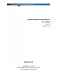
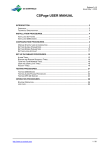
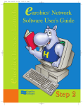
User Manual
Version 1.0
INTRODUCTION ........................................................................................................................................ 2
SYSTEM REQUIREMENTS...................................................................................................................... 2
MINIMUM SPECIFICATIONS:........................................................................................................................ 2
RECOMMENDED SPECIFICATIONS: .............................................................................................................. 2
WINDOWS INSTALLATION.................................................................................................................... 2
FROM THE WEB .......................................................................................................................................... 2
FROM A CD ................................................................................................................................................ 2
EXECUTABLE .............................................................................................................................................. 2
USER INTERFACE..................................................................................................................................... 3
THE 3D MAP WINDOW ............................................................................................................................... 4
What Appears in the 3D Map Window.................................................................................................. 4
Using the Mouse to Get Around in the 3D Map Window...................................................................... 6
THE COAST PILOT TEXT WINDOW ............................................................................................................. 7
Feature links ......................................................................................................................................... 7
Regulation Links ................................................................................................................................... 7
Regulation Display Window.................................................................................................................. 8
Web links............................................................................................................................................... 8
THE CONTROL PANEL................................................................................................................................. 8
The Find Pane....................................................................................................................................... 9
The Display Options Pane .................................................................................................................... 9
The View Control Pane ......................................................................................................................... 9
The Feature Information Pane............................................................................................................ 10
MENU ITEMS ............................................................................................................................................ 10
FileÆ Exit........................................................................................................................................... 10
Edit Æ Preferences… ......................................................................................................................... 11
Help Æ GeoCoastPilot Help............................................................................................................... 12
Help Æ About GeoCoastPilot............................................................................................................. 12
CREDITS .................................................................................................................................................... 12
GeoCoastPilot User Manual Version 1.0
1
Introduction
GeoCoastPilot turns the NOAA Coast Pilot® manual into an interactive document linked to a 3D
map environment. GeoCoastPilot provides linkages between the written text, 2D and 3D views,
web content, and other primary sources such as charts, maps, and related federal regulations.
System requirements
Minimum Specifications:
•
•
•
•
•
•
1.8 GHz Pentium 4 or AMD Athlon processor or better
At least 512 MB RAM
Video card with at least 128MB of onboard memory
CD-ROM drive
At least 300 MB of free hard drive space
Windows 2000 or Windows XP
Recommended Specifications:
•
•
•
•
•
•
3.0 GHz Pentium 4 or AMD Athlon processor or better
At least 1 GB RAM
Video card with at least 256MB of onboard memory
CD-ROM drive
At least 300 MB of free hard drive space
Windows XP
Windows Installation
Currently, GeoCoastPilot is only distributed for the Windows platform. If you would like to
install on another platform, please send a request to [email protected].
From the Web
Download the GeoCoastPilot_install.exe installation program from
http://www.ccom.unh.edu/vislab/projects/GeoCoastPilot.html, and run it. See Executable section
below for more details.
From a CD
Insert the CD. If the installation program does not automatically start, open a file browser and
find the GeoCoastPilot_install.exe file and double-click it. See Executable section below for
more details.
Executable
Once the installation program is running, follow the on-screen directions. The
installation procedure starts by asking you to agree to a user agreement. It then gives you
a choice where you would like to install it (the default is usually sufficient). It then
installs the files necessary to run GeoCoastPilot on your computer. Finally, it creates a shortcut
GeoCoastPilot User Manual Version 1.0
2
on your desktop that you can double-click to launch GeoCoastPilot, and it creates a
GeoCoastPilot folder in your StartÆPrograms Windows menu that contains the shortcut and an
“Uninstall” icon you can use to remove GeoCoastPilot from your computer.
User Interface
The GeoCoastPilot interface consists of three main components: the 3D Map window, the Coast
Pilot Text window, and the Control Panel. You can give more space to the 3D Map or the Coast
Pilot Text and Control Panel by clicking and dragging the sash that divides them.
3D Map
Sash
Coast Pilot Text
GeoCoastPilot User Manual Version 1.0
Control Panel
3
The 3D Map Window
The 3D Map window primarily provides a 3D view of an area, but it also provides several tools
for interpreting and controlling the view (circled in red below). This section describes what
appears in the 3D scene being viewed, how to use the mouse to get around in the 3D scene, and
how the various tools work.
What Appears in the 3D Map Window
GeoCoastPilot displays several types of information in the 3D Map window: S-57 ENC data,
photographic imagery of key features, bathymetric (3D surface) data, and raster charts. It also
has a compass and a color key indicating depth levels.
S-57 ENC Data. GeoCoastPilot displays a subset of the
available S-57 Electronic Nautical Chart (ENC)
information, including buoys, lights, bridges, various areas
(caution, anchorage, cable, dredged, etc.), and landmarks.
This data is always showing. You can click on any part of
the S-57 data to get information on that part in the Feature
Information pane (described in the Control Panel section).
Photographic Imagery. A central feature of GeoCoastPilot is that it displays photographs of key
features identified in the NOAA Coast Pilot® text. Many features have photographs taken from
multiple angles, corresponding to the angles you might take when approaching these features.
GeoCoastPilot automatically displays the photograph that is closest to the current viewing angle.
The photographs are exaggerated in size to varying degrees based on their relative importance,
and how close they are to the middle of the screen. This is intended to make it easier to establish
where the features are even at scales where you would not normally be able to make them out.
For more about changing the amount of exaggeration, see the Display Key Features portion of the
Control Panel section, and the part about Feature Exaggeration under the EditÆPreferences…
menu item.
GeoCoastPilot User Manual Version 1.0
4
The photographic imagery is also interactive. If you click on photograph of a feature, it brings up
the first mention of that feature in the text in the Coast Pilot Text window, and may display
additional information in the Feature Information pane.
Bathymetric Data. Bathymetric data is
3D surface information that provides an
illustration of what the area might look
like with the water drained. In some
sense, it is best to treat this data as a sonar
“photograph” of the bottom. While it
shows many bottom-surface features in
fine detail, some of these features are
dynamic or transitory—like birds, boats,
or autumn leaves in a visual photograph.
The bathymetric data is color-coded
according to depth, similar (but not identical) to the NOAA raster charts: yellow for land, light
green for areas that uncover at low water, and blues and whites for successively deeper areas. For
more about the color coding, see the sections about the Color Key tool and the Adjustable
Contour Levels in the EditÆPreferences… menu item.
Raster Charts. Portions of selected NOAA raster charts can be displayed instead of bathymetry.
See the discussion about the Base Display of the Control Panel section for more information.
The 3D Compass. There is a compass in the bottom
right hand corner of the 3D Map window that indicates
the direction of true north. The compass is bowed
inward at the middle and the letters at the rose points
pivot so they are always facing you. This design makes
it possible to read the compass reasonably well at any
pitch or heading.
GeoCoastPilot User Manual Version 1.0
5
The Color Key. In the bottom left hand corner of the 3D Map window is a color key
that you can use to interpret depths from the colored bathymetry. The area in darker
blue is intended to indicate areas covered by water at MLLW (mean lower low
water), but that are too shallow for your vessel to enter. The light blue area is
intended to act as a cautionary buffer zone below your keel. You can change the
default values of 10 and 20 feet by changing the Adjustable Contour Levels under the
EditÆPreferences… menu item (described later). You can click and drag anywhere on the color
key to move it around the GeoCoastPilot application. Click on the color key then press the “m”
key on the keyboard to see the levels in meters, or press “f” to see the levels in feet again.
Using the Mouse to Get Around in the 3D Map Window
GeoCoastPilot offers several different ways to use the mouse to get around in the 3D Map
Window. No matter which way you choose, the scene will temporarily degrade, and then will fill
in with detail once you’re done moving.
Click-and-Drag. This is probably the method familiar to most users—the ability to click and
drag the scene around with the mouse. Regardless of the angle of view, you can click and drag
the scene as if it were a sheet of paper sitting on a table behind the screen.
Double-click. You can also double click on any surface in the 3D scene. If you click on a
photograph of a feature, the scene will smoothly animate toward that feature and attempt to orient
the view to directly face the feature. Otherwise, the view will smoothly animate toward where
you double-clicked, and will turn to face the direction of travel.
Rolling Forward or Back on the Mouse Scroll Wheel. If you have a 3-button mouse with a
scroll wheel, then you can click in the 3D Map view and then zoom in by rolling the scroll wheel
forward, or zoom out by rolling it back.
Clicking a Coast Pilot Feature. If you click a red, underlined feature in the Coast Pilot Text
window, the scene with smoothly animate toward that feature and attempt to orient the view to
face it. For more information, see the Coast Pilot Text Window section.
Using the View Control Pane on the Control Panel. You can change the position and
orientation of the view by entering values for position or heading and pressing the Goto button in
the Control Panel, or by pressing one of the other buttons in the Control Panel. See the discussion
about the View Control pane in the Control Panel section for more information.
The Rotation & Measurement Tools (or 3D Control Widgets).
At the center of the 3D Map window is a set of crosshairs with a
ring on top. On the ring is a pink slider that controls the
heading of the 3D Map window. You can click and drag the
pink slider clockwise or counter-clockwise to rotate the view
accordingly. If you click and drag on the ring itself or on the
cone in the center of the ring, you can pull the ring back and
forward to change the tilt angle. The crosshairs have distance
markers on them that indicate vertical and horizontal metric
GeoCoastPilot User Manual Version 1.0
Heading slider
6
distance from the center of the screen. You can click and drag the black markers toward or away
from the center to zoom out or zoom in, respectively. If you want to hide these 3D Control
widgets, press the Rotation & Measurement Tools button in the Control Panel.
The Scale Scrollbar. There is a scrollbar at the right of the 3D Map window that is used to
control the scale of view. Scrolling up corresponds to zooming in to see greater detail, while
scrolling down corresponds to zooming out. At either end of the scale scrollbar are buttons
with magnifying glass icons. These will cause the view to zoom in or out in large
increments. You can also use the center scroll wheel on your mouse to control scale.
The Coast Pilot Text Window
The Coast Pilot Text window shows the all the text from Chapter 9 of the 2007 edition of the
NOAA Coast Pilot®, Book 1. It has been reformatted to work better on a computer screen. You
can scroll through the text either by
using the scrollbar at the right side of
this window, or by clicking in the
window and using the arrow keys or
the center scroll button found on some
mice. It is also possible to select text
and copy it using Ctrl+C on the
keyboard to paste it into other
documents, although any formatting
of the text will be lost.
Feature links
Text that is underlined and shown in
dark red represents a feature link.
Clicking on one of these links causes
three things to occur. First, the feature
is highlighted in red wherever that
Feature Links
feature appears in the Coast Pilot Text Highlighted Feature Link
window. Second, if there is support information for the feature in the S-57 database, it is shown
in the Feature Information pane at the bottom of the Control Panel. And third, the 3D Map
window centers on that feature (or if the feature is too far off the map, it heads toward the feature
and stops).
Regulation Links
Text that is underlined and shown in
brown represents a regulation link.
Clicking on one of these links causes the
regulation display window to appear
with a listing of the regulations
referenced in the text.
GeoCoastPilot User Manual Version 1.0
7
Regulation Display Window
Like the Coast Pilot Text window, the
regulation display window contains text
from the Code of Federal Regulations, but
reformats it somewhat for the purpose of
electronic display. You can scroll through
the text using either scrollbar, and select and
copy text to paste into other documents.
You can also move the window around
using the title bar, resize the window by
dragging on any of its edges, or close the
window by pressing the small x button in the
upper right-hand corner.
The text in this window may differ from what the NOAA Coast Pilot® reproduced in Chapter 2,
but only in that it may include additional information that may not be applicable to marine
applications. Title, chapter, and part designations are formatted in blue of various font sizes,
while section headings are bold and black. Tables of contents appear in green (these tables are
usually omitted in the NOAA Coast Pilot®). Other information that may be of interest but is not
included in the NOAA Coast Pilot® is shown in italicized grey text.
Web links
Text that is underlined and shown in dark blue
represents a link to an external web resource.
Clicking on one of these links will cause a
web browser to be launched with the indicated resource displayed.
The Control Panel
The Control Panel consists for four
major panes: The Find pane (topleft corner), the Display Options
pane (immediately below), the View
Control pane (top-right corner), and
the Feature Information pane (at the
bottom). This section describes how
to use each of these panes, and how
they tie into the other main
components of the GeoCoastPilot
interface.
GeoCoastPilot User Manual Version 1.0
8
The Find Pane
The Find pane makes it possible for you to search for a
string of text in the Coast Pilot Text window. To use it,
enter the text you want to search for in the white text entry
box, and then press the Find > button (Find forwards). If
the text is found, then the first instance of it (starting from
where you are in the text) will be highlighted in light blue. You can keep pressing the Find >
button to find the next instance of it, and the search will wrap around to the beginning if there are
no more matches below. To search backward through the Coast Pilot text, press the < button
(Find backwards).
The Display Options Pane
Both display options in this pane affect the 3D Map window.
Base Display. When GeoCoastPilot first starts up it does not
show a nautical chart, but instead shows high resolution
bathymetry—an illustration of what the area might look like with the water drained. You can
view part of the NOAA raster charts by using the appropriate radio toggle buttons, but the
bathymetry will disappear. You can toggle the view by selecting either the Nautical Chart
choice or the Bathymetry choice. In both display modes the S-57 ENC data remains on top.
Display Key Features. GeoCoastPilot normally exaggerates key features like lighthouses, range
markers, and prominent landmarks so that they are visible at wide scales. You can restore them
to their actual size by using the appropriate radio toggle buttons. You can toggle between actual
size and exaggerated features by clicking on the Actual size choice or the Exaggerated choice,
respectively. To change the amount of exaggeration, change the Feature Exaggeration item in
the Edit GeoCoastPilot Preferences dialog (under EditÆPreferences… in the menu).
The View Control Pane
The View Control basically summarizes the position and
orientation of the 3D view, and provides you with ways to
control that view. At the top are the latitude and longitude of the
center of the 3D view in degrees-minutes-seconds format. Just
below that the latitude and longitude are repeated in decimaldegrees format. Just below these are the heading (relative to True North) and pitch (0° would
correspond to looking out to the horizon, while 90° provides a top-down view as if from the belly
of an airplane). You can enter your own values in any of the white entry boxes and press the
Goto button to change the view manually, but your values will be overridden if the view changes
for other reasons.
The next row of buttons provides several additional ways to control the view. You can press the
Home button to return the 3D Map back to the original view it had when GeoCoastPilot first
started up. If you press the Aerial button, the pitch (vertical viewing angle) changes to 28° and
GeoCoastPilot User Manual Version 1.0
9
the scale automatically adjusts to compensate. Press the Overview button to change the pitch to
90° and automatically scale out to compensate a bit. You can press the NorthUp button to force
the 3D Map view to maintain a view heading of 0° no matter what might otherwise
change the heading. The view will continue to remain in the pink “down” position and
maintain a heading of 0° in the 3D Map until you press the NorthUp button again,
returning it to the “up” position..
The Show Rotation & Measurement Tools button at the
bottom of the View Control pane causes the 3D control widgets
to appear or disappear. When the button is in the pink “down”
position, the 3D control widgets are shown at the center of the
3D Map view. When the button is in the grey “up” position,
the widgets disappear.
The Feature Information Pane
The Feature Information pane lists
information about the last feature
you clicked in either the Coast Pilot
Text window or the 3D Map
window. This information comes
from S-57 ENC data. This display
generally contains all the important
information available in the US Coast Guard Light List, plus some additional information that
may help clarify the attributes of the selected feature.
Sometimes a feature is actually composed of multiple S-57 items. When this happens, only one
of the items is displayed in the Feature Information pane. We expect to provide a way to select a
feature from a list of related items in a future version of GeoCoastPilot.
Menu Items
This section describes the features of GeoCoastPilot that are accessible through the menu at the
top left corner of the application.
FileÆ Exit
Selecting this causes settings to be saved and then exits GeoCoastPilot.
GeoCoastPilot User Manual Version 1.0
10
Edit Æ Preferences…
Selecting this causes the Edit GeoCoastPilot Preferences dialog to
appear.
There are several settings in GeoCoastPilot that you can change and have them remain the next
time you start GeoCoastPilot. The Edit GeoCoastPilot Preferences dialog allows you to access
some of these settings. To bring up this dialog, select “Preferences…” from the “Edit” menu. If
you make changes to settings on this dialog, you can
immediately see the effects of those changes without closing the
dialog by clicking on the Apply button. When you’re done, hit
the OK button to apply changes and close the dialog. If you
don’t like the changes you’ve made since you last hit the Apply
button, you can press the Cancel button to close the window and
keep the current settings. Here is a brief description of each of
the settings you can change:
Startup Options.
Automatically download latest CFRs on startup. CFR stands for Code of Federal Regulations.
The NOAA Coast Pilot® refers to this body of regulations on several occasions, and reproduces
relevant regulations in Chapter 2. Rather than provide a copy of Chapter 2, GeoCoastPilot
contains reproductions of the latest versions of the CFR from the official site,
http://www.access.gpo.gov/nara/cfr/cfr-table-search.html. By default, GeoCoastPilot downloads
the latest versions of all the regulations it refers to on startup. If you are not connected to the
Internet, or find that the download process causes problems, you can disable this feature by
making sure this option is unchecked.
Adjustable Contour Levels. Since GeoCoastPilot uses high resolution bathymetry to
represent the seafloor, it can generate color-coded contours at practically any depth.
These two settings allow you to change two of the contours for your convenience.
Changes are reflected in updated contours and in the color key as soon as you apply
the changes.
Keel contour depth (at MLLW). This is the contour at the color change from dark
blue to light blue. It is intended to represent the depth of the keel of your vessel, and therefore
shades in dark blue the areas that would be inaccessible at MLLW (mean lower low water). You
can enter in any value (in feet) that is less than the Caution Contour value.
Caution contour depth (at MLLW). This is the contour at the color change from light blue to
white. It is intended to represent a safety buffer between your keel and the bottom. This buffer
area is shaded in light blue, indicating areas that may be unsafe to transit at MLLW (mean lower
low water). You can enter in any value (in feet) that is greater than the Keel Contour value.
3D User Interface Options.
Animation speed (default 100%). GeoCoastPilot relies heavily on the graphics card in your
computer to create high-resolution images and smooth animations from feature to feature. As
GeoCoastPilot User Manual Version 1.0
11
such, it may be necessary to either speed up or slow down the animation. This option allows you
to adjust the speed of animation. If the animation is too slow, try a higher number (such as 150).
Alternatively, if the animation seems too fast, try a lower number (like 75 or 50).
Feature Exaggeration (default 0.55). The exaggeration of features (photographs) in the 3D Map
area of GeoCoastPilot is partially dependent on the size of your screen. If you find that the
exaggeration still leaves the images too small, try increasing this number (to, say, .65 or .75). If
images seem too large and distracting, try decreasing this number (to .40 or .33, for example).
Help Æ GeoCoastPilot Help
Selecting this menu item causes this document to be launched in
a PDF reader. If you do not have a reader, you can install Adobe
Acrobat Reader for free from www.adobe.com/reader.
Help Æ About GeoCoastPilot
Selecting this menu item causes the splash screen to be displayed
again. This screen has information about which version of
GeoCoastPilot you are running, and how to contact its creators.
You can close the splash screen by clicking on the OK button.
Credits
The text that appears in the Coast Pilot Text window comes directly from the NOAA Coast
Pilot®.
Compass image modified from Compass_rose_pale.svg by the Wikipedia user named Fibonacci.
An archive copy can be found at
http://commons.wikimedia.org/wiki/Image:Compass_rose_pale.svg along with the GNU Free
Documentation license under which it is distributed.
GeoCoastPilot User Manual Version 1.0
12