1
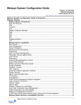
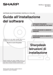
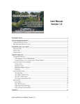
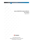
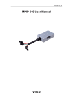
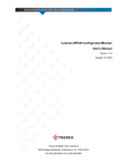
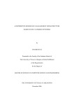
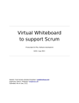
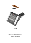
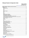
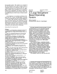
Release 3.4.5 Issued May 1, 2008 CSPage USER MANUAL INTRODUCTION ....................................................................................................................... 2 OVERVIEW ............................................................................................................................... 2 TECHNICAL SPECIFICATION....................................................................................................... 3 INSTALLATION PROCEDURES .............................................................................................. 4 INSTALLING SOFTWARE ............................................................................................................ 4 INSTALLING GSM MODEM ......................................................................................................... 4 CONFIGURATION PROCEDURES .......................................................................................... 4 CSPAGE STARTUP AND AUTHORIZATION ................................................................................... 4 SETTING GLOBAL PARAMETERS ................................................................................................ 6 SETTING MODEM PARAMETERS .............................................................................................. 10 SETTING LOGIN ACCOUNT ...................................................................................................... 11 SET-UP DATABASE PROCEDURES .................................................................................... 12 ALARM TABLE ........................................................................................................................ 12 ROSTER AND ROSTER SCHEDULE TABLE................................................................................. 14 TEAM AND TEAM MEMBER TABLE ............................................................................................ 16 USER AND USER LEAVE TABLE ............................................................................................... 18 HOLIDAY TABLE ..................................................................................................................... 19 TESTING PROCEDURES....................................................................................................... 21 TESTING GSM MODEM .......................................................................................................... 21 TESTING ALARM PAGING PROCEDURE .................................................................................... 22 TESTING OPC AE SERVER .................................................................................................... 24 OPERATION PROCEDURES ................................................................................................. 26 ROUTINE OPERATION ............................................................................................................. 26 LOG FILES.............................................................................................................................. 26 http://www.cs-controls.com 1 / 28 Release 3.4.5 Issued May 1, 2008 Introduction CSpage is an alarm management software product, which can be used on Johnson Controls M3/M5 workstations, VE800 or other OPC AE server. It can provide BAS with direct and comprehensive alarm paging and notification capabilities. CSpage also has a comprehensive roster shift feature. Overview CSpage includes 3 function modules: 1. Alarm capturing module: It is OPC AE client software which can get alarm/event from BAS OPC AE server. It can also support Metasys PMI/Metahost, and ADS/ADX, NAE55 serial printer port as alarm input. 2. Paging objects processing module: It’s a database process, which can assign correct roster/team/user information to the alarm, and send the alarm object to the modem buffer at designed time. 3. Modem module: It’s a process to send the alarm out by SMS (Short Message System). It includes SMS buffer and modem implementation software. An alarm from OPC AE server can be captured by the CSpage and send to a Roster (or multi Rosters in special application) The Roster will select an active team from the roster schedule by Weekday/Holiday/Alternative day, and assigns the active team to this alarm. An object then will be created with the information (alarm name, active team, delay interval, retry times and so on) and be saved into a WaitQ (as WaitQ object). In CSpage, there is a thread to check the WaitQ periodically to see whether it is time for an alarm to be paged to a user. If yes, the alarm message and contact number will be taken out from WaitQ and saved into a SMS buffer in the form of paging object. If the GSM modem is connected, the paging object will be taken out quickly and sent to the destination. If the modem doesn’t work, the paging objects will keep being stored until the GSM modem is recovered (The buffer size is 1000). The operator can clean this buffer if he doesn’t want to send out the huge number of SMS accumulated during the modem failure. The paging time is decided as follows: Each alarm is assigned with an active team, and one team is divided into 2 groups of people: Normal and Manager. http://www.cs-controls.com o The alarm will be sent to the normal group user first. If the user SMS back the some message, CSpage will consider it as acknowledge and stop paging to the next person (the software can also be configured in other way, to page the next person even the alarm is acknowledged, or even cancel the acknowledgement feature) o If there is no acknowledgement from user, the alarm will be re-sent until the predefined retry times are finished. The interval can be predefined (Normal Delay, typically 1 minutes) o Then the alarm will be sent to next user and go on until all the normal users are paged. 2 / 28 Release 3.4.5 Issued May 1, 2008 o The system will wait for a predefined time (Group Delay, typically 15 minutes), and then start to page the alarm to Manager Group. o The paging process is the same as the Normal group except with different predefined interval (Manager Delay, typically 10 minutes) So that in a typical application, if there is no one to acknowledge the alarm. All of the managers will be informed. Every user can be defined with many on-leave periods. During an onleave period, the user will not be paged. All of the tables, include Alarm, Roster, Team, Team schedule, User, User on-leave ... can be defined to unlimited records (only limited by the PC resource), and provide operators with great flexibility. The CSpage has 2 level of login password. It will restrict the access right of an operator to different parts of CSpage. “Normal” level is for database modification, whereas “Manager” level is for parameter setting and testing. The CSpage include 2 log files: o One for paging: It records all of the paging process and acknowledge situation, which can be used for facility manger to check whether the service is efficient. o One for event: It records the entire important event in CSpage, which is for BAS engineer to do troubleshooting. It can even monitor who has changed the database, modified the global setting or closed the software. It has license control feature. Without software license enable, CSpage will auto-close in one hour. This makes it difficult be used in illegal commercial case, but not restricts from training, testing and commissioning. It has manually alarm acknowledging/purging features from Acknowledge interface. It has auto-purge feature to purge the alarm. Unacknowledged alarm will be erased from WaitQ after the pre-defined time. o Technical Specification http://www.cs-controls.com Alarm Source Type: OPC AE Server: For M3, M5, VE800 or any third party HMI which can support OPC AE Server. Metahost: For Metasys PMI RS232: For ADS/ADX alarm printer, and NAE55 DDA (alarm printer) Operation System: Microsoft® Windows ® 2000 Service Pack 4 Microsoft Windows XP ® Microsoft Windows NT® Version 4.0 with Service Pack 6 or later Microsoft Windows 98 Second Edition Recommended PC Platform: Pentium® III class, 1 GHz, 512MB RAM Software Requirement: M5 workstation, or M3 workstation, or Other OPC AE (Ole for Process Controls, Alarms and Events) 1.1 server Required Third Party Components: 3 / 28 Release 3.4.5 Issued May 1, 2008 GSM (Global System for Mobile Communications) modems which support AT commands GSM 07.05 for SMS. E.g.: o Siemens TC35 GSM modem or Siemens MC35i modem. Installation Procedures Installation procedures include software installation and hardware installation. Installing Software The CSpage is programmed by .net 2003. It needs to install dotNetFramework1.1 and Internet Explorer 6.0 SP1 before install CSpage. Install IE6 SP1: If your OS does not have IE6 SP1, install IE6 SP1 from \ IE60SP1 Install dotNetFramework1.1: Insert installation CD in CD driver, and click \dotNetFramework1.1\ dotnetfx.exe. The installation may need some other system upgrading. Follow the instruction to install necessary upgrading, and run the installation again. Install CSpage: Click \CSpage\ CSpage.msi, and follow the instructions. Accept all of the default except select "Install CSpage for every one". The operator can also click Setup.Exe if your OS doesn't support .msi file (windows installation package file) Check: After proper installation, you can find the CSpage.exe software at StartÆPrograms Æ CSpage Installing GSM modem Connect the cable according to the modem manual. Connect RS232 cable to the PC’s COM port. Connect antenna to the modem Insert the SIM card into the modem. Make sure to take out the SIM card’s password if any. There is no need to install any modem driver on the PC Configuration Procedures CSpage Startup and Authorization Run the CSpage by clicking the CSpage.exe at StartÆProgramsÆCSpageÆCSpage.exe. Figure 1: CSpage Main User Interface http://www.cs-controls.com 4 / 28 Release 3.4.5 Issued May 1, 2008 Table 1: Operation of main interface Function Implementation Start Run the CSpage by clicking the CSpage.exe, or from StartÆProgramsÆCSpageÆCSpage.exe. From menu MainÆLogin, then key in login name and password. The default login name is “admin” and password is “1234”. Login The login password includes 2 levels: Normal and Admin. The Admin level can access all of the functions under menu “Normal” and “Admin”, whereas Normal level can only access the functions under menu “Normal”. From menu MainÆAuthorization, then key in the site key. The site key can get from CSpage support team by submitting the installation key copied from this interface. (tip: site key is not easy to key in manually, It is recommended to use soft copy, or get by SMS from the GSM modem as in Figure 16) Authorization If the operator doesn’t get site key, the CSpage also allows the operator to implement all of the configuration, testing and other functions, but the system will automatically close itself in 60 minutes. The operator needs to re-start the software by clicking the CSpage.exe again. From menu MainÆLogout. Logout Close http://www.cs-controls.com It is recommended that the operator should logout after finishing the configuration, to prevent unauthorized operation by others. From menu MainÆExit and key in login name and password, and the software will be closed. 5 / 28 Release 3.4.5 Issued May 1, 2008 Setting Global Parameters To setup global parameters, the operator needs to login the system by admin level password (default is “Admin”, “1234”), and then click menu AdminÆGlobal Cfg Figure 2: Global Parameter (General) Configuration Table 2: Global Parameter (General) Field Description Field/Button Description Log Editor The text editor (notepad or WordPad) used for displaying log files. Using WordPad is recommended since it can store more content. Date Format The date format used in CSpage. This data format will be used in log file and other situation. Protocol Type http://www.cs-controls.com The protocol used by CSpage to get incoming alarm. Alarm AutoPurging Time (minutes) The time (in minutes) of CSpage will wait before it purges the alarms object stored in WaitQ. Incoming Alarm Block time (minutes) The time interval (in minutes) of blocking incoming alarm after the user clicks menu specialÆBlock Incoming Alarm. Time Stamp Whether the alarm message received by user will include alarm occur time. Alarm Object Whether the alarm message received by user will include alarm object name. Tag Number Whether the alarm message received by user will include alarm tag number. Note: Only “No Acknowledgement” scenario can disable sending tag number. The other 2 “Acknowledgement” scenarios will omit this setting and send tag number in SMS. No acknowledgement Disable the acknowledgement feature. Once an alarm occurs, it will be paged to all of the users in the active team. 6 / 28 Release 3.4.5 Issued May 1, 2008 Acknowledgement will stop paging Once the alarm is acknowledged, it will stop paging to other users in the same team. Acknowledgement is done by sending back the SMS with the received content. CSpage will check the tag number to deduce which alarm is acknowledged. Acknowledgement won’t stop paging Once the alarm is acknowledged, it will continue paging other users in the same team. But the acknowledgement information will be recorded in log file. Block Recurred Alarms from Paging If it’s checked, CSpage will treat a BAS point which sends alarms many times in certain period (2 hours by default) as one alarm tag. Only occurring time will be changed according to the latest alarm. Save Save the setting to registry. If you have changed protocol type and or the OPC AE name, you need to re-boot the software. Cancel Cancel the setting. Figure 4: Global Parameter (OPC AE) Configuration If the alarm source is OPC AE server, these parameters on “Global Configuration (OPC AE)” need to be configured. Please refer to “CSpage for OPC AE” for details. http://www.cs-controls.com 7 / 28 Release 3.4.5 Issued May 1, 2008 Table 4: Global Parameter (OPC AE) Field Description Field/Button Description Node Name The computer name or IP address on which OPC server is located. This is for DCOM. Keep it blank if the OPC server is on the same PC as CSpage. OPC AE Name The name of OPC Alarms and Events server which will send alarm to CSpage. It is recommended to use “Browse Server” button to get the exact name. Browse Server Browse the OPC AE servers available. The operator can select one from the combo box. The operator can also key in the OPC AE server name. Category If ticked, it will be added as part of Alarm name Type If ticked, it will be added as part of Alarm name Severity If ticked, it will be added as part of Alarm name Condition If ticked, it will be added as part of Alarm name SubCondition If ticked, it will be added as part of Alarm name Separator Save Cancel The separator in Alarm name between fields. Save the setting to registry. Cancel the setting. Notes: In normal application, user needs only tick “Condition”, and then the Alarm name format is Source.Condition. In situation that “Condition” is not enough to differentiate the alarm. “SubCondition” can be ticked. So that the alarm name format is Source.Condition.SubCondition. And so on so forth. When use CSpage in an unfamiliar OPC AE, it is recommended to use “OPC Test” interface to test before to make decision on which fields should be used in Alarm Name. Figure 5: Global Parameter (Metahost) Configuration If the alarm source is Metahost, these parameters on “Global Configuration (Metahost)” need to be configured. Please refer to “CSpage for Metahost” for details. http://www.cs-controls.com 8 / 28 Release 3.4.5 Issued May 1, 2008 Table 5: Global Parameter (Metahost) Field Description Field/Button Description Metahost IP Addr. The IP address of Metahost (in M5 workstation) Trigger Factor Please refer to manual “CSpage for Metahost” Alarm Content Please refer to manual “CSpage for Metahost” Save Cancel Save the setting to registry. Cancel the setting. Figure 6: Global Parameter (Alm Printer Port) Configuration If the alarm source is ADS/ADX alarm printer, NAE55 DDA alarm printer, , these parameters on “Global Configuration(Alm Printer Port)” need to be configured. Please refer to “CSpage for Alarm Printer Port” for details. Figure 7: Global Parameter (Duty/Standby) Configuration If the Duty/Standby feature is required, these parameters on “Global Configuration (Duty/Standby)” need to be configured. Please refer to “CSpage for Duty/Standby” for details. http://www.cs-controls.com 9 / 28 Release 3.4.5 Issued May 1, 2008 Figure 8: Global Parameter (SMS format) Configuration CSpage can support other SMS format in other languages. “Text mode” is for pure English, and “PDU mode” is for Unicode. Table 5: Global Parameter (SMS format) Field Description Field/Button Text mode (For pure English) PDU mode (for other languages) Setting Modem Parameters Description For pure English For Unicode support To setup modem parameters, the operator needs to login the system by admin level password, and then click menu AdminÆ Modem Cfg. Figure 9: Modem Configuration http://www.cs-controls.com 10 / 28 Release 3.4.5 Issued May 1, 2008 Table 6: Modem Configuration Field Description Field/Button Modem Type The type of the modem. Port Name Define which com port is used for modem. Baud Rate The baud rate used to communicate with modem. Save Cancel Setting Login Account Description Save the setting to registry. Cancel the setting. Login data table is the place to manage login names and passwords. To setup login data table, the operator needs to login the system by admin level password, and then click menu AdminÆ Login Data. Figure 10: Login data Configuration Table 7: Login Data Field Description Field/Button Description Login Name The login name used to access CSpage configuration and testing functionality. Password The password for the login name. Level Password level. Level “Normal” can access menu “Normal”; Level “Admin” can access menu “Normal” and “Admin”. Save Save the setting to registry. Cancel Cancel the setting. * Delete record: Highlight the record and push “Del” button of keyboard http://www.cs-controls.com 11 / 28 Release 3.4.5 Issued May 1, 2008 Set-up Database Procedures Database set-up in CSpage is by 5 main interfaces (Alarm, Roster, Team, User and Holiday), and 3 sub interfaces (Roster Schedule, Team Detail, and User Leave). To configure database, the operator needs to login the system by “Normal” or ”Admin” level. Alarm Roster Roster Schedule Team Team Detail User User Leave Holiday Figure 11: Database structure of CSpage Alarm Table Open Alarm database interface by clicking menu Normal Æ Alarm Alarm Database. Figure 12: Alarm Table http://www.cs-controls.com 12 / 28 Release 3.4.5 Issued May 1, 2008 Table 8: Alarm Table Field Description Field/Button Description Data grid Name Alarm name. The default format is: “Source”. “Condition”. E.g.: 1. The alarm’s source “JC\Ahu_3-1\Trip”, name is 2. The alarm’s condition name is “Alarm”, 3. Then “JC\Ahu_3-1\Trip.Alarm” is the alarm name for this field. The source and condition can be checked from “OPC test” interface from menu AdminÆOPC testÆAll Event Display. One alarm can be defined multi times with different roster assigned in special application case (multi-roster application) Customized Alarm name format can be defined in “Global Cfg”Æ”OPC AE”. Desp Roster Alarm description. The Roster assigned to the alarm. Once an alarm occurs, this is the start point to find an active user to page the alarm message. Message The message to be sent if the alarm occurs. Group Box Alarm Name Alarm name. (It is duplication from “Name” field of present record for easier input.) Message The message to be sent out if the alarm occurs. (It is a duplication from “Message” field of present record for easier input) Update Grid Update the present record with the information in group box. Add Record Add a new record in data grid. Duplicate selected record If ticked, the newly added record will duplicate the content of present record. Frame Save Save the modification to database, and refresh the interface. Cancel Cancel the modification. Roster Display Roster interface. * Delete record: Highlight the record and push “Del” button of keyboard http://www.cs-controls.com 13 / 28 Release 3.4.5 Issued May 1, 2008 Roster and Roster Schedule Table Open Roster database interface by clicking menu NormalÆRoster, or clicking button on Alarm table interface. Normal Æ AlarmÆRoster. Figure 13: Roster Table Table 9: Roster Table Field Description Field/Button Name Description Retries Description Name of the roster. Description of the roster. Paging retry times before paging next user. Normal Dly(s) Paging interval (in seconds) between users in normal group. This parameter also applies to retry paging in this group. Grp Dly(s) Paging interval (in seconds) between normal group and manager group. Mgr Dly(s) Paging interval (in seconds) between users in manager group. This parameter also applies to retry paging in this group. Save Save the modification to database, and refresh the interface. Cancel Roster Schedule Cancel the modification. Display Roster Schedule interface of present record. * Delete record: Highlight the record and push “Del” button of keyboard Open Roster Schedule database interface by clicking button on Roster configuration interface: NormalÆRosterÆ Roster Schedule http://www.cs-controls.com 14 / 28 Release 3.4.5 Issued May 1, 2008 Figure 14: Roster Schedule Table Table 10: Roster Schedule Table Field Description Field/Button Description Active time. Time After this time, the active team will be used for paging until the next active team definition. If there is no team is defined in the particular day, the active team will be the last active team of the day before and so on. Active team. At the defined day/time, a roster will use the active team to send alarm. Team Save Cancel Add Record Team Holiday If a date is defined as holiday/alternative day, at that particular day, the roster will chose active teams from holiday/alternative table instead of week schedule table. Save modification to database, and refresh the interface. Cancel modification. Add a new record into data grid. Display team interface. Display holiday interface. * Delete record: Highlight the record and push “Del” button of keyboard http://www.cs-controls.com 15 / 28 Release 3.4.5 Issued May 1, 2008 Team and Team Member Table Open Team database interface by clicking menu NormalÆTeam, or clicking button on Roster Schedule table interface. NormalÆRosterÆRoster ScheduleÆTeam Figure 15: Team Table Table 11: Team Table Field Description Field/Button Description Name Team name. Save Save the modification to database, and refresh the interface. Cancel Team Detail Cancel the modification. Display Team Member interface for present record * Delete record: Highlight the record and push “Del” button of keyboard Open Team Member database interface by clicking button on Team configuration interface: NormalÆTeamÆ Team Detail. http://www.cs-controls.com 16 / 28 Release 3.4.5 Issued May 1, 2008 Figure 16: Team Member Table Table 12: Team Member Table Field Description Field/Button Description Normal User Group User Name Order Name of the team member, in normal group. Paging sequence order. Manager Group User Name Order Name of the team member, in manager group. Paging sequence order. Button Save Cancel Save the modification to database, and refresh the interface. Cancel the modification. Add Add a new record. User Display the User table interface for present record. * Delete record: Highlight the record and push “Del” button of keyboard http://www.cs-controls.com 17 / 28 Release 3.4.5 Issued May 1, 2008 User and User Leave Table Open User table interface by clicking menu NormalÆUser, or clicking button on Team Member table interface: NormalÆTeamÆTeam Detail ÆUser. Figure 17: User Table Table 13: User Table Field Description Field/Button Description Data grid Name User name. Type Media type. SMS: Short Message System Number Hand phone number. Button Save Cancel Leave Setting Save the modification to database, and refresh the interface. Cancel the modification. Display the User On-Leave interface for present record. * Delete record: Highlight the record and push “Del” button of keyboard Open User Leave database interface by clicking button on User configuration interface: NormalÆUserÆ Leave Setting. http://www.cs-controls.com 18 / 28 Release 3.4.5 Issued May 1, 2008 Figure 18: User On-Leave Table Table 14: User On-Leave Table Field Description Field/Button Description Data grid Start Leave start date/time. End Leave end date/time. Interface Start Select date/time of “leave start” for a new record. (datetimepicker control) End Select data/time of “leave end” for a new record. (datetimepicker control) Save Save the modification to database, and refresh the interface. Cancel Cancel the modification. New Record Add a new record to data grid. The start/end date/time is according to the present value of start/end datetimepicker controls. Purge Present Purge the present user’s leave. That is to delete all of the leave records with end data/time earlier than present time. Clear Present Delete the present user’s leave. That is to delete all of the leave records. * Delete record: Highlight the record and push “Del” button of keyboard Holiday Table http://www.cs-controls.com Open Holiday database interface by menu: NormalÆHoliday 19 / 28 Release 3.4.5 Issued May 1, 2008 Figure 19: Holiday Table Table 15: Holiday Table Field Description Function Action Data Grid Date Day Type The Date to be defined as holiday/alternative day. The type of the day. Menu Action Add Holiday The date from the MonthCalendar control will be sent to data grid as a new holiday record. One date can’t be defined as both Holiday and Alternative Day, otherwise, an error message will be displayed, and the definition will be canceled. Add Alternative The date from the MonthCalendar control will be sent to data grid as a new alternative day record. Button Save Cancel Save the modification to database, and refresh the interface. Cancel the modification. * Delete record: Highlight the record and push “Del” button of keyboard http://www.cs-controls.com 20 / 28 Release 3.4.5 Issued May 1, 2008 Testing Procedures CSpage includes 3 function modules: alarm capturing, paging objects processing and modem operation. To simplify the T&C, 3 testing interfaces are designed to let operator test the function modules separately. It is recommended that the operator conduct all three testing procedures before conducts whole system commissioning. Testing GSM Modem This testing is to make sure that the GSM modem, SIM card, and modem configurations are working properly. To conduct the testing, the operator needs to 1. Login the CSpage by Admin level password, and configure the modem from modem interface (AdminÆModem Cfg) as describe in Table 5. 2. From AdminÆGlobal CfgÆAcknowledge, select radio button “No Acknowledgement”. This will make sure that the operator can read the SMS in GSM modem, since other configuration will let the CSpage purge the SMS in modem. 3. Click AdminÆModem Test, and the Modem Test interface will be displayed. Figure 20: Modem Test Interface Table 16: Modem Test Interface Description http://www.cs-controls.com 21 / 28 Release 3.4.5 Issued May 1, 2008 Field/Button Modem name Description Select a modem to be tested. Modem Feedback The content that the modem feedback from com port. If the last word if “false”, that means the modem doesn’t have a feedback. If the last word is “true”, that means the modem communication is ok. HP/Pager Number The HP/Pager number that the testing message will be sent to. Message to be Sent The testing message to be sent. The number of SMS will be read or deleted. Number of SMS to be Read/Cleared The Siemens TC35 can store maximum 30 received SMS. The content in this field will determine how many SMS will be read (by clicking Read SMS), or deleted (by clicking Clear Modem Buffer). Click this button will get modem internal information: ATI: modem model Get Modem Info AT+CPI: Whether the SIM card has pin protection. If show “ERROR”, please take out the pin protection on SIM card AT+COPS: Whether links to ISP, and the name of ISP. Chk Modem Click this button will send a test command to modem by COM, and the content in Modem Feedback can be used to determine whether the modem communication with CSpage is OK. The last word of feedback is the result. “true” for ok, “false” for error Send Msg Click this button will send a SMS to the cell phone with the number defined in “HP Number”, and the content defined in “Msg to be Sent”. Read SMS Click this button will get the SMS content received by GSM modem. The content will be displayed in “Modem Feedback”. The number of SMS is defined in “Number of SMS to be Read/Cleared”. Clear Modem Buffer Click this button will clear the SMS content in GSM modem, and release the buffer for further receiving SMS. The number of SMS to be cleared is defined in “Number of SMS to be Read/Cleared”. For Siemens TC35 modem, the maximum number is 30. Testing Alarm Paging Procedure This testing is to make sure that the paging process is working properly. To conduct this testing, the operator needs to login the CSpage by Admin level password. http://www.cs-controls.com 22 / 28 Release 3.4.5 Issued May 1, 2008 Click menu AdminÆTest Alarm, and key in the alarm name (tip: the operator can copy alarm name from Alarm table interface Figure 8), then clicks OK. A simulated alarm will be inserted into the system WaitQ. Notes: If you insert the same alarm twice into the system, they won’t be handled as 2 alarms, only the last occurred alarm will be inserted into WaitQ (use the last alarm occurring time to update the AT field). This design also applies to real alarms from OPC. Click menu NormalÆ Acknowledge, and “Acknowledge Alarms” interface will be displayed, to let the operator check the paging situation and do manual acknowledgement. Figure 21: Acknowledge Interface If a real alarm occurs, and match the Alarm table, the generated alarm objects is also stored in WaitQ and can be checked and acknowledged in this interface. http://www.cs-controls.com 23 / 28 Release 3.4.5 Issued May 1, 2008 Table : Acknowledge Interface Description Field/Button Description Data grid Tag Alarm At Roster A number to differentiate alarms. Alarm name. Alarm occur time. Assigned roster of the alarm. Team Active team assigned for the alarm. Retry Present paging retry count. e.g.: 1 is 1 retry, means 2 more paging for the particular destination. 0 is no retry, means 1 paging for the particular destination. Position Present paging sequence order in present group. It counts from 0 to the number of users minus 1. E.g.: A normal group has 3 users assigned with order (1,3,5). The position shown here will be: 0,1,2 Level Present paging group. Normal: means it is paging in Normal group. Manager: means it is paging in Manager group. Finished: means this alarm’s paging has been finished. Button Acknowledge Clear All SMS Buffer Check Testing OPC AE Server Delete the present alarm. It will delete the alarm object in the WaitQ. Delete the all of the alarms in the WaitQ. Display the SMS buffer. The present version of CSpage has a buffer with the capacity of 1000 SMS. This is for the storing the SMS when the modem can’t operate. Once the modem is connected and work properly, the SMS in the buffer will be sent out through the modem. Click the button “Clear buffer” will clear the buffer, and the SMS accumulated in the buffer won’t be sent out even when the modem is back to normal. This testing is to make sure that the OPC AE Client is working properly and can get alarms from BAS. Click menu AdminÆOPC Test, and the “OPC Test” interface will be displayed. Note: The OPC AE server must be connected to the CSpage before the operator can use this interface. That means the operator needs to check http://www.cs-controls.com 24 / 28 Release 3.4.5 Issued May 1, 2008 whether the Status Bar panel 2 is displayed with “BAS: true”. Otherwise, the BAS system and/or OPC configuration (AdminÆGlobal CfgÆGeneralÆOPC AE Setup) need to be properly configured. Figure 22: OPC Test Interface From OPC Test interface and click button “Display All Event”, an OPC subscription interface will be displayed. When BAS trigs an alarm, the alarm should be shown on this interface. The operator can use the content of “Source” and “Condition” to create alarm name in Alarm table definition. Figure 23: OPC Alarms and Event display interface. http://www.cs-controls.com 25 / 28 Release 3.4.5 Issued May 1, 2008 Operation Procedures Routine Operation During routine operation, follow the following procedure to make sure the system is under correct status: 1. Click StartÆProgramsÆCSpageÆCSpage.exe to start the software 2. Check the status bar panel 1. It should be empty or “Login Name:” If it shows: “no license! The system will stop in 60 mins.” it means the software is not authorized. A license needs to be installed. If it shows: “Login Name: xxxx”, it means the software is under login status. It is recommended that the operator logout if he has finished the configuration. 3. Check the status bar panel 2. It should show “BAS: true”. If it shows: “BAS: false”, it means the BAS system is not properly connected to the CSpage. Need to check configuration of CSpage OPC AE configuration and/or BAS system. 4. Check the log file. If it can’t show log file, the operator need to check the log file reader configuration. 5. If for testing or other purpose, the user wants to block the incoming alarms: Click SpecialÆBlock Incoming Alarms, this will block the incoming alarms and won’t let them send SMS out. The user can click SpecialÆRelease Incoming Alarms to cancel this feature. If blocking incoming alarm feature is started, it will be auto released within certain minutes (can be define in AdminÆGlobal cfg). The operation status and remaining minutes is displayed on status bar. Log files There are 2 log files are designed in CSpage. Event Log is for recording all the events of the system, and PageLog is for recording all of the paging activities. The log files are created by the system. If an operator deletes/moves a log file, the CSpage will auto create a new one at the directory of the CSpage. To open EventLog file, click menu MainÆLogFileÆEventLog To open PageLog file, click menu MainÆLogFileÆPageLog http://www.cs-controls.com 26 / 28 Release 3.4.5 Issued May 1, 2008 Figure24: Event Log file Table 18: Event Log file Field Description Field Description TIME The time when the action/result occur. Event Event of the system. Figure25: Page Log file http://www.cs-controls.com 27 / 28 Release 3.4.5 Issued May 1, 2008 Table19: Page Log file Field Description Field TIME ALARM AT Mobile Tag ACTION/RESULT Description The time when the action/result occur. Alarm name. The time when the alarm occurs. Mobile number, or others. A number to differentiate alarms. Each newly occurred alarm will be assigned with on unique tag number. The tag will be set to 0 when system boot-up, and increases the number with each of the new assignment. Action or action result of the system. Table20: Definition of action/result field in PageLog file Content SYS DEL The alarm is deleted by system purge. NO ACTIVE TEAM Alarm is defined in system, but can’t find an active team. (This is normally caused by no team is defined in Roster Schedule database). NO ACTIVE STAFF Alarm is defined in system, and has an active team, but no active user can be found. (This is normally caused by no user is defined in Team interface, or all of the users are in on-leave period. CREATE Alarm is captured and creates a WaitQ record in system. SENT http://www.cs-controls.com Description Message has been sent out. RESENT Message has been re-sent out. This is by retry action. PC DEL One alarm record in WaitQ is deleted from Acknowledgement interface. PC CLR All of the alarm records in WaitQ are deleted from Acknowledge interface. USR ACK A user acknowledges the alarm by SMS, but the alarm record is not deleted. (This is caused by system acknowledge setting, or the alarm record is already deleted before the user SMS back). USR DEL A user acknowledges the alarm by SMS, and the alarm record is deleted from WaitQ. 28 / 28