1
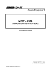
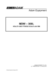
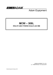
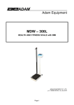
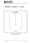
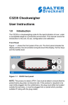
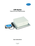
Model SBI-140 Indicator
User Manual
AWT35-000056 Issue A
AWT35-000056
Model SBI-140 Indicator
User Manual
©Avery Berkel Limited 2006. All rights reserved.
The information contained herein is the property of Avery Berkel Limited and is supplied without liability for errors or omissions. No
part may be reproduced or used except as authorised by contract or other written permission. The copyright and the foregoing
restriction on reproduction and use extend to all media in which the information may be embodied.
Salter Brecknell is a trading name of Avery Berkel Limited
2
Model SBI-140 Indicator
User Manual
Contents
WARNINGS.................................................................................................................................................. 4
Setup Instructions......................................................................................................................................... 5
Desk/Wall Bracket ........................................................................................................................... 5
Power Supply .................................................................................................................................. 5
Installing Batteries ........................................................................................................................... 6
Connecting Indicator to Platform ..................................................................................................... 6
General Operating Instructions .................................................................................................................... 7
Display............................................................................................................................................. 7
Manual symbols............................................................................................................................... 8
Indicator Operation ....................................................................................................................................... 8
Turning On and Zeroing the Indicator ............................................................................................. 8
Turning off the Indicator................................................................................................................... 8
Selecting Unit of Measure ............................................................................................................... 9
Removing the Tare .......................................................................................................................... 9
Hold Function - Automatic Zero on Next Weigh............................................................................ 10
Hold Function - Manual Release ................................................................................................... 10
Removing Hold .............................................................................................................................. 11
Print Function ................................................................................................................................ 11
Serial Interface Settings ................................................................................................................ 11
Error Messages ............................................................................................................................. 12
User Configuration Settings........................................................................................................................ 13
Setup Controls............................................................................................................................... 13
Configuration Settings ................................................................................................................... 14
Data Commands for Bi-directional Interface ................................................................................. 15
Display, Measurement and Service Settings.............................................................................................. 16
Scale setup and calibration ........................................................................................................... 16
Setup controls................................................................................................................................ 16
Service Settings............................................................................................................................. 16
Scale calibration ............................................................................................................................ 18
Declarations of Compliance ....................................................................................................................... 19
United States ................................................................................................................................. 19
Canada .......................................................................................................................................... 19
CE (Declaration of Conformity) ..................................................................................................... 19
3
Model SBI-140 Indicator
User Manual
WARNINGS
Safe installation
Safety
THE EQUIPMENT CONTAINS NO USER SERVICEABLE COMPONENTS.
Installation and maintenance of the equipment must only be carried out by trained and authorised
personnel.
Electrical installation
The mains lead must be connected to a supply outlet with a protective earth contact. The
electrical supply at the socket outlet must provide over current protection of an appropriate rating.
For your protection all mains (110V or 230V) equipment used out of doors or in wet or damp
conditions should be supplied from a correctly fused source and protected by an approved
ground fault protection device (RCD, GFCI etc.)
IF IN DOUBT SEEK ADVICE FROM A QUALIFIED ELECTRICIAN.
Routine maintenance
To avoid the possibility of electric shock or damage to the machine, always switch off the
machine and isolate from the power supply before carrying out any routine maintenance.
To avoid the risk of the machine falling, where applicable, ensure that it is placed securely on a
flat and level surface.
Safe use
Caution – Cleaning the indicator/weigh head
Harsh abrasives, solvents, scouring cleaners and alkaline cleaning solutions, such as washing
soda, should not be used especially on the display windows. Under no circumstances should you
attempt to wipe the inside of the machine.
The outside of standard products may be wiped down with a clean cloth, moistened with water
containing a small amount of washing up liquid.
The outside of products waterproofed to IP65, IP66 and IP67 may be washed down with water
containing a small amount of proprietary detergent.
Training
Do not attempt to carry out any procedure on a machine unless you have received the
appropriate training or read the Instruction Manual.
EMC compliance
The following may be applicable to your machine.
WARNING:
This is a class A product. In a domestic environment this product may cause radio interference in
which case the user may be required to take adequate measures.
4
Model SBI-140 Indicator
User Manual
Setup Instructions
Desk/Wall Bracket
By changing the angle blocks as shown below, the indicator bracket can be converted into a wall
mounting bracket.
Power Supply
5
Model SBI-140 Indicator
User Manual
Installing Batteries
Connecting Indicator to Platform
If necessary, wire the cable attached to the base as shown.
6
Model SBI-140 Indicator
User Manual
General Operating Instructions
Display
Max
D=
Zero
>0<
Net
/
Hold
Print
/ >0<
Tare
UNITS
On/Off
Zero
Model SPI-140
Function Keys
Annunciators
0
I
On/Off
Zero
Centre of zero
On/Off/Zero
Net
T
Tare
Net weight displayed
Activate the tare
Hold activated
kg/lb
Select unit
Units
kg, lb, oz
Hold
Print
kg
Hold/Print
7
Active unit of measure
Scale in motion
Model SBI-140 Indicator
User Manual
Manual symbols
Short key press
Multiple key press
Long key press
Indicator Operation
Turning On and Zeroing the Indicator
Zero
>0<
kg
HOLD
Net
1.
Zero
>0<
kg
HOLD
Net
2.
Turning off the Indicator
Zero
>0<
Net
8
HOLD
Model SBI-140 Indicator
User Manual
Selecting Unit of Measure
kg
HOLD
kg → lb → lb.oz.
Using the Tare
Zero
>0<
kg
HOLD
Net
1.
Zero
>0<
kg
HOLD
Net
2.
Zero
>0<
kg
HOLD
Net
3.
Zero
>0<
kg
HOLD
Net
4.
Removing the Tare
Zero
>0<
Net
.
9
kg
HOLD
Model SBI-140 Indicator
User Manual
Hold Function - Automatic Zero on Next Weigh
kg
HOLD
1.
kg
HOLD
kg
HOLD
2.
kg
HOLD
3.
kg
HOLD
kg
HOLD
4.
Hold Function - Manual Release
This function needs to be set up in Parameter P3.1 shown on page 14.
kg
HOLD
1.
kg
HOLD
kg
HOLD
2.
kg
3.
10
HOLD
Model SBI-140 Indicator
User Manual
Removing Hold
kg
HOLD
1.
Print Function
For communications to a printer or PC, the indicator has to be set up in the following parameters P2, P4,
P5 and P6.
Zero
>0<
Net
1.
2.
3. Print
Gross: 45.00kg
Tare:
1.45kg
Net:
43.65kg
Serial Interface Settings
RS232 serial interface wiring:
Pin/xxxxxx/xxxxx/xxxx/
2
(TXD)
3
(RXD)
4
(DSR)
5
(GND)
6
(DTR)
7
(CTS)
8
(RTS)
1
2
6
11
7
5
4
3
8
9
kg
HOLD
Model SBI-140 Indicator
User Manual
Error Messages
Error Message
Definition
Required Solution
Weight above range for calibrated
zero point
Remove load before zeroing,
-orRecalibrate the scale.
0_____:
Weight below range for calibrated
zero point
Remove load before zeroing,
-orRecalibrate the scale.
_____:
Indicates an under-range condition
Remove all loads, and zero the
scale.
¯ ¯ ¯ ¯:
Capacity exceeded
Remove the load, and try again.
A greater capacity scale may be
required.
CAL-Er:
Calibration error
Restart calibration.
Lo.bAt:
Low Battery
Recharge the battery.
0¯ ¯ ¯ ¯:
12
Model SBI-140 Indicator
User Manual
User Configuration Settings
Setup Controls
kg
kg
Moves flashing digit
Change flashing digits
Exits setup mode
Saves data and move down
to next parameter setting
.
1. Entering Setup
HOLD
+
2. Selecting parameter
3. Changing data within parameter
HOLD
kg
Zero
>0<
Net
4. Saving data
Zero
>0<
kg
HOLD
Net
5. Exiting setup
Zero
>0<
Net
13
kg
HOLD
Model SBI-140 Indicator
User Manual
Configuration Settings
Parameter
P1.xx
Setting
Default settings in bold
P1.00
P1.01 – P1.15
P1.05
Auto shut-off timer in minutes
Set up time for the auto-off function
(00 = 0ff, 01-15 = time in minutes)
P2.x
Hold and print key functionality
Set up button function
0 = Press button once to activate hold.
1 = Press button once to print.
2 = Press button to print. Press and hold button to activate hold.
P3.xx
Hold Function Settings
0 = No hold function active.
1 = Animal averaging hold with manual push-button release.
The weight reading is held on the display until a higher weight is applied.
This automatically releases the held weight and re-holds it at the new
higher weight reading.
P2.0 = Hold
P2.1 = Print
P2.2 = Print & Hold
P3.0
P3.1
P3.2
P3.3 to 50
2 = Animal averaging hold with automatic release and re-hold.
As above, but the weight reading is held on the display until the platform
is emptied and the next weight reading over 10 divisions is applied.
3-50 = Selectable hold window from +/- 3 to 50 divisions.
Once stable, holds display reading within a selectable weight range. Must
be re-pressed to release the hold button.
P4.x
RS232 – Serial Interface
Settings for serial interface
0 = No RS232 output.
1 = Once stable, print displayed data when print key is pressed.
2 = Once stable, print gross, tare and net weight when print key is
pressed.
P4.0
P4.1
P4.2
P4.3
P4.4
P4.5
P4.6
P4.7
3 = Continuously output gross weight.
4 = Continuously output gross, tare and net weight (compatible with NCISP1).
5 = Once stable, print displayed data one time only.
6 = Once stable, print gross, tare and net weight one time only.
7 = Bidirectional-RS232 (also compatible with NCI-SP1).
P5.x
RS232 Baud rate
P5.0 = 1200 P5.3 = 9600
P5.1 = 2400 P5.4 = 19200
P5.2 = 4800
P6.x
RS232 Data format
P6. 0
P6. 1
P6. 2
0 = 8 digits, no odd or even, 1 start bit, 1 stop bit
1 = 7 digits, 1 even, 1 start bit, 1 stop bit
2 = 7 digits, 1 odd, 1 start bit, 1 stop bit
P7-P19 .x
SERVICE CONFIGURATIONS ONLY (See page 16.)
Any adjustment to these settings could seriously affect the indicators performance. Seek advice
from a service engineer before changing.
14
Model SBI-140 Indicator
User Manual
Data Commands for Bi-directional Interface
The RS232 can be set so a bi-directional connection can be established between the indicator and the
host. To establish this connection, set parameter P4 to 7, so it is compatible with the NCI-SP1.
Commands can then be sent from the host to the indicator using the following commands (ensure the
letters entered are in CAPS) (<CR> = Enter).
Command
Action
Response
W<CR>
Takes a reading
<LF>^^^^^^^^^u1u2<CR><LF>H1H2H3<CR><ETX>
Over capacity - Under
<LF>_______u1u2<CR><LF>H1H2H3<CR><ETX>
capacity - Zero point error <LF>----------u1u2<CR><LF>H1H2H3<CR><ETX>
- Reading (kg or lb)
<LF><p>w1w2w3w4w5w6<dp>w7u1u2<CR><LF>H1H2H3<CR><ETX>
S<CR>
Prints Status Bytes
<LF>H1H2H3<CR><ETX>
Z<CR>
Zeros the scale
<LF>H1H2H3<CR><ETX>
T<CR>
Sets up a tare
<LF>H1H2H3<CR><ETX>
U<CR>
Changes the units
<LF>u1u2<CR><LF>H1H2H3<CR><ETX>
L<CR>
Activates the hold function <LF>H1H2H3<CR><ETX>
X<CR>
Switches off the scale
Indicator switches off.
Unrecognised command
<LF>?<CR><ETX>
?
Key Symbols
<LF>
Line feed
<p>
Polarity character including minus sign for negative
weigh and space character for positive
<CR>
Carriage return
W1-W7
Weight data
<ETX>
End of text character
<dp>
Decimal point
<SP>
Space
U1U2:
Unit measure, kg, lb or oz
H1H2H3
3 status bytes
Output Status Bit Meaning
Bit
Byte 1
Byte 2
Byte 3
0
0 = Stable
1 = Unstable
0 = Not Under Capacity
1 = Under Capacity
00 = Not defined
01 = Normal working mode
1
0 = Not at zero point
1 = At zero point
0 = Not over capacity
1 = Over capacity
0 = Hold working mode
1 = Not defined
2
Always 0
Always 0
0 = Gross weight
1 = Net weight
3
0 = eprom OK
1 = eprom error
Always 0
Always 0
4
5
6
Always 1
Always 1
Always 1
Always 1
Always 1
Always 1
Always 0
Always 1
Always 0
7
Parity
Parity
Parity
15
Model SBI-140 Indicator
User Manual
Display, Measurement and Service Settings
WARNING! Any adjustment to these settings could seriously affect indicator performance. Seek
advice from a service engineer before changing.
Scale setup and calibration
Before calibrating, the following parameter must be setup correctly:
P7
P8
P9
P10
Scale resolution (500 ~ 10000)
Division size
(1, 2 or 5)
Decimal place
(10 ~ 0.0001)
Calibration unit of measure lb or kg
For scale calibration, see page 18.
Setup controls
kg
kg
Moves flashing digit
Change flashing digits
Saves data and moves down
to next parameter setting
Exits setup mode
For entering setup, refer to page 12.
Service Settings
Parameter
Settings
Default settings in bold
P7.xx
Displayed resolution in divisions
Graduations - Specifies number of full-scale
graduations.
P7.00 = 500
P7.01 = 600
P7.02 = 750
P7.03 = 800
P7.04 =1000
P7.05 =1200
P7.06 =1500
P7.07 =2000
P7.08 =2400
P7.09 =2500
P7.10 =3000
P8.x
Displayed divisions size:
Multiples of: 1, 2 or 5
P8.0 = 1
P8.1 = 2
P8.2 = 5
P9.x
Decimal point position
P9.0 = 1
P9.1 = 0.1
P9.2 = 0.01
P10.x
Calibration unit of measure.
Select the unit of measure the scale will be calibrated
in.
P11.x
Units of measure:
Selects the units of measure the scale will operate in
from the unit’s key.
16
P7.11 = 3500
P7.12 = 4000
P7.13 = 5000
P7.14 = 6000
P7.15 = 7000
P7.16 = 7500
P7.17 = 8000
P7.18 = 10000
P7.19 = 12000
P7.20 = 15000
P7.21 = 20000
P7.22 = 25000
P7.23 = 30000
P7.24 = 35000
P7.25 = 40000
P7.26 = 50000
P7.27 = 60000
P7.28 = 70000
P7.29 = 75000
P7.30 = 80000
P7.31 = 100000
P9.3= 0.001
P9.4= 0.0001
P9.5= 10
P10.0 = kg
P10.1 = lb
P11.0 = only kg
P11.1 = only lb
P11.2 = only lb:oz
P11.3 = kg or lb
P11.4 = kg or lb:oz
P11.5 = lb or lb:oz
P11.6 = kg, lb, or lb:oz
Model SBI-140 Indicator
User Manual
Service Settings Continued
Parameter
P12.x
Settings
Power up Zero range
Selects the Power up zero-point range based on the
calibration zero point.
P13.x
Zero button range
Selects the zero range the zero buttons can zero off.
P14.x
Scale Power up when inside the power up zero range
Allows the scale to power up and zero from the following
point.
P15.x
0= Power up and zero at any weight.
1= Power up zero based off calibration zero-point.
2= Power up back at the zero-point the scale was
powered off at and also display any active tare.
Scale Power up when outside the power up zero range
Allows the scale to power up and display the following:
P16.x
0= Zero and display in current Gross weight.
1= Displays Gross weigh based off calibration zero point.
2= Displays Gross or Net weight based off the zero-point
of
when the scale was last powered Off.
3= Continuously display error message “0¯¯¯¯”
Zero tracking range
P17.x
Data filter intensity
P18.x
Check weight stability range
P19.x
Overload limit range
17
Default settings in bold
P12.0 = +1%
P12.1 = +2%
P12.2 = +5%
P12.3 = +10%
P12.4 = +20%
P12.5 = +50%
P12.6 = +100%
P12.7 = No limitation
P13.0 = ±1%
P13.8 = +1%
P13.1 = ±2%
P13.9 = +2%
P13.2 = ±5%
P13.10 = +1%
P13.3 = ±10%
P13.4 = ±20%
P13.5 = ±50%
P13.6 = ±100%
P13.7 = No limitation
P14.0
P14.1
P14.2
P15.0
P15.1
P15.2
P15.3
P16.0 = off
P16.1 = ±0.25d
P16.2 = ±0.5d
P16.3 = ±1d
P16.4 = ±1.5d
P17.0 = very weak
P17.1 = weak
P17.2 = middle
P17.3 = strong
P18.0 = ± 0.5d;
P18.1 = ± 1d
P18.2 = ± 1.5d
P18.3 = ± 2d
P18.4 = ± 3d
P19.0 = 0
P19.1 = + 9d
P19.2 = 101%
P19.3 = 102%
P19.4 = 105 %
P16.5 = ±2d
P16.6 = ±3d
P16.7 = ±4d;
P16.8 = ±5d
P18.5 = ± 4d
P18.6 = ± 5d
P18.7 = ± 6d
P18.8 = ± 7d
P18.9 = ± 8d
P19.5 = 110%
P19.6 = 120%
P19.7 = 150%
P19.8 = 200%
P19.9 = No limitation
Model SBI-140 Indicator
User Manual
Scale calibration
Calibration can be done with 25% to 100% of full load and can be calibrated with 1 or 2 calibration points.
HOLD
+
1.
HOLD
HOLD
2.
HOLD
HOLD
3.
4. Enter in calibration weight from 25% to 100% full capacity.
HOLD
25%-100%
100.00
kg/lb
5. For single-point calibration, enter the same weight in again and move to number 7.
For 2-point calibration, enter in the second calibration weight between 25% and 100% full capacity.
HOLD
HOLD
6.
HOLD
25%-100%
50.00
kg/lb
HOLD
HOLD
7.
HOLD
8.
Zero
>0<
Net
9.
18
kg
HOLD
Model SBI-140 Indicator
User Manual
Declarations of Compliance
United States
This equipment has been tested and found to comply with the limits for a class A digital device, pursuant
to Part 15 of the FCC Rules. These limits are designed to provide reasonable protection against harmful
interference when the equipment is operated in a commercial environment. This equipment generates,
uses, and can radiate radio frequency energy and, if not installed and used in accordance with the
instruction manual, may cause harmful interference to radio communications. Operation of this
equipment in a residential area is likely to cause harmful interference in which case the user will be
required to correct the interference at his own expense.
Canada
This digital apparatus does not exceed the Class A limits for the radio noise emissions from digital
apparatus set out in the Radio Interference Regulations of the Canadian Department of Communications.
Le présent appareil numérique n’émet pas de bruits radioélectriques dépassant les limites applicables
aux appareils numériques de la Classe A prescrites dans le Règlement sur le brouillage radioélectrique
edicté par le ministère des Communications du Canada.
CE (Declaration of Conformity)
Declaration of Conformity
Manufacturer
Salter Brecknell
Type
SBI 140
Corresponds to the requirements of the following EC directives:Electro Magnetic Compatibility Directive:
Low Voltage Directive:
The application harmonised standards are:
EMC 89/336/EEC
LVD 73/23/EEC
EN60950
EN50081-1
EN50082-1
A copy of the original signed declaration for this instrument is available from the UK address below.
USA
UK and Europe
Salter Brecknell Weighing Products USA
1000 Armstrong Drive
Fairmont
MN 56031
Toll Free: 800-637-0529
Phone: 507-238-8702
19
Fax: 507-238-8271
email:[email protected]
www.salterbrecknell.com
Salter Brecknell Weighing
P.O. Box 9533, Smethwick,
West Midlands, B66 2TE.
United Kingdom.
Tel: +44 (0) 870 444 6132
Fax: +44 (0) 870 010 2241
email:[email protected]
www.salterbrecknell.co.uk