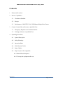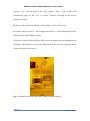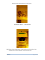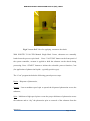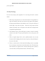
1
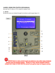
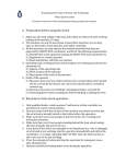
NANOELECTRONICS FABRICATION FACILITY (NFF), HKUST Standard Operating Manual ___________________________________________________________ SOLITEC 5110-C/PD Manual Single-Head Coater Version 1.0 Page 1 of 14 NANOELECTRONICS FABRICATION FACILITY (NFF), HKUST Contents 1 Picture and Location 2 Process Capabilities 3 4 2.1 Cleanliness Standard 2.2 Recipes 2.3 Performance of SOLITEC 5110-C/PD Manual Single-Head Coater Contact List and How to Become a Qualified User 3.1 Emergency Responses and Communications 3.2 Training to Become a Qualified User Operating Procedures 4.1 System Description 4.2 Safety Warnings 4.3 Operation Rules 4.4 Initial System Checks 4.5 Status Checks 4.6 Steps to operate the equipment 4.6.1 Manual Resist Dispense 4.6.2 Clean up the equipment after use Version 1.0 Page 2 of 14 NANOELECTRONICS FABRICATION FACILITY (NFF), HKUST 1. Picture and Location Exhaust Pipe Vacuum Switch 2”, 4” and specimen spin chucks SOLITEC Controller Front Panel Spin Coating Chamber with lid SOLITEC 5110-C/PD Manual Single-Head Coater Fig.1 SOLITEC 5110-C/PD Manual Single-Head Coater This tool is located at NFF Enterprise Center Cleanroom Room 4162 2. Process Capabilities 2.1 Cleanliness Standard SOLITEC 5110-C/PD Manual Single-Head Coater is a “Non-Standard” equipment for photoresist coating process. Version 1.0 Page 3 of 14 NANOELECTRONICS FABRICATION FACILITY (NFF), HKUST 2.2 Recipes The standard recipes for this equipment are shown at the NFF official webpage (https://www.nff.ust.hk/mffdoc/Labprocessdata/project5/docs/default.htm). Users can edit recipes based on the thickness and resist type which the process requires. For any enquires of recipe editing, please contact NFF EC staff. 2.3 Performance of SOLITEC Manual Resist Coater Spin Speed Range 0 - 5000 RPM Spin Timing Range 1 - 999 seconds Substrate size 2” & 4” or specimens 3. Contact List and How to Become a Qualified User 3.1 Emergency Responses and Communications Security Control Center: 2358-8999 (24hr) & 2358-6565 (24hr) Safety Officer: Mr. Wing Leong CHUNG 2358-7211 & 64406238 Deputy Safety Officer: Mr. Man Wai LEE 2358-7900 & 9621-7708 NFF EC Technician: Mr. Peter Yiu Cheong PUN 2358-7225 & 2358-7218 NFF Phase 2 Technician: Mr. Wilson Pui Keung YIP 2358-7894 Version 1.0 Page 4 of 14 NANOELECTRONICS FABRICATION FACILITY (NFF), HKUST 3.2 Training to Become a Qualified User Please follow the procedure below to become a qualified user. 1. Read the operation manual of SOLITEC 5110-C/PD Manual Single-Head Coater which can be found in NFF web site. 2. Send an e-mail to NFF requesting SOLITEC 5110-C/PD Manual Single-Head Coater operation training. Scheduling can take up to several weeks due to the many requests coming in for this tool. 3. 4. Operating Procedures 4.1 System Description Fig.2a SOLITEC 5110-C/PD Controller Front Panel Version 1.0 Page 5 of 14 NANOELECTRONICS FABRICATION FACILITY (NFF), HKUST Fig.2b SOLITEC 5110-C/PD Controller Front Panel A: Process System Power/Vacuum/Start/Stop Switches, with Vacuum and Motor Purge Interlock Indicators B: Digital Readout – Actual Speed is RPM x 1000 C: Servo Motor Ramp Setting Dial Indicator (000 – Fast / 999 – Slow) D: Process Function Cycle Timer (Time Length Select – Total Time MAX. of 99.9 or 999 seconds, depending on cycle function) E: Resist Select Switch – Up to five different sources can be selected F: Dispense Select Switch (Auto – Process Run, Liquid Dispense / Off – Process Run, No Liquid Dispense) G: Process Head Position Select Switch (Down – Process Head in the “Down” Version 1.0 Page 6 of 14 NANOELECTRONICS FABRICATION FACILITY (NFF), HKUST position / Up – Process Head in the “Up” position / Auto – Process Head will automatically move to the “Up” or “Down” position according to the process functions selected) H: Process Function Select Switch – Selects Either “Coat” or “Develop”. I: Spindle Speed Control (0 – 999 setting equivalent to 0 – 9999 RPM) [Please Limit Speed to below 5000 RPM for Safety] J: Process Function Select Switches (When press the function key,the pushbutton will illuminate. Then the process will start (indicated from the left to the right side shown on the front panel) successively. Fig.3 Controller Front Panel and Spin Coating Chamber with Lid Version 1.0 Page 7 of 14 NANOELECTRONICS FABRICATION FACILITY (NFF), HKUST Fig.4 Spinner Chucks (2”, 4” and specimens) Fig.5 Spinner Chuck, Spindle Motor, Coating Chamber with Lid and Heavy Duty Aluminum Foil covering to maintain a clean around the coater Version 1.0 Page 8 of 14 NANOELECTRONICS FABRICATION FACILITY (NFF), HKUST Fig.6 Vacuum Ball Valve for applying vacuum to the chuck With SOLITEC 5110-C/PD Manual Single-Head Coater, substrates are manually loaded onto the process spin chuck. Press “VACUUM” button on the front panel of the system controller, vacuum is applied to hold the substrate on the chuck during processing. Press “START” button to initiate the selectable process function, Coat (for application of photoresist liquids – typically positive type). The “Coat” program includes the following general process steps: Resist – Dispense of photoresist; Spread – Low-to-medium speed spin to spread the dispensed photoresist across the substrate; Spin – Medium-to-high speed spin to create the proper thickness of photoresist across the substrate and to “dry” the photoresist prior to removal of the substrate from the Version 1.0 Page 9 of 14 NANOELECTRONICS FABRICATION FACILITY (NFF), HKUST process spin chuck. 4.2 Safety Warnings Users can cause injury by this equipment if it is not being used under a cautious manner. 1. When using O-ring chuck, the area of the chuck inside the O-ring should be as large as the substrate. Since this area increases as the square of the diameter, the largest practical diameter chick should be used. To keep the coefficient of friction high, O-ring clean and elastic. Check the O-ring contact with the substrate by placing a piece of flat glass on the chuck and verifying that the O-ring flattens against the glass. 2. If the substrate is heavy, such as thick glass or ceramic, it must be accurately centered on the chuck. The spin speed should be as low as the process will allow. 3. With an irregular shaped wafer, such as gallium-arsenide, the user must develop the skill of judging where the center of gravity is and positioning it in the center of the chuck. 4. If there is a leak on the face of the chuck while holding a wafer, it is probably due to an improper contact between the chuck and the wafer. Flat chucks may leak if substrates are rough or bowed. Check the following items: (a) Burrs or cuts on the chuck, (b) Warped substrate and (c) Thin chuck O-ring. Version 1.0 Page 10 of 14 NANOELECTRONICS FABRICATION FACILITY (NFF), HKUST 4.3 Operation Rules 1. If the equipment alarms during operation, do not try to fix the problem by yourself and should report to NFF staff immediately. 2. Do not operate the equipment unless you are properly trained and approved by NFF staff. 3. Do not leave an on-going experiment unattended. 4. Do not run the process for more than 999 seconds. 5. Do not start the process while the door is still open. 6. Do not open the door while processing. 7. Except “main menu” and “Process for Engineering menu”, do not click into other menus such as “Maintenance menu”. 8. Do not stop the process by improper ways during normal operation. For example, turn off the power suddenly to stop the process. 9. Do not change the machine settings without permission of NFF staff. 10. Apart from photoresist, it is not allowed to spin coat the other unapproved materials. 4.4 Initial System Checks 1. Make sure the equipment is ready (Pass initial system checks). 2. To dispense photoresist with the automatic resist dispense switch in the “OFF” position (controller front panel), proceed as follows: 3. After completing the start-up procedure and with the power and vacuum on, place a substrate on the chuck, centering it as best as possible. 4. Select spin chuck for your sample, e.g. 2”, 4” wafers or specimens (Fig 4). 5. Press the VACUUM button to apply vacuum to the chuck. Version 1.0 Page 11 of 14 NANOELECTRONICS FABRICATION FACILITY (NFF), HKUST 6. Select the “SPREAD” cycle, by pressing the SPREAD function button, (should illuminate the button). 7. Set the desired time and speeds for the “SPREAD” and “SPIN” cycles. 8. Low speed spin spread of photoresist chemical (SPREAD). 9. High speed spin dry (SPIN). 10. Apply the desired amount of photoresist, you should use the rubber bulb and pipette to drop the photoresist. Do not pour the photoresist through the bottle. 11. Press the START button. 12. After the SPREAD and SPIN cycles have been completed, and the spindle is stopped, release the VACUUM button and remove the substrate. Remark: A completed check list of SOLITEC 5110-C/PD Manual Single-Head Coater is provided. User must follow the procedures and fill in the list before operation. 4.5 Status Checks Reservation is needed for this equipment. Please book and check in the equipment before operation. 4.6 Steps to Operate the Equipment 4.6.1 Manual Resist Dispense 1. Make sure the equipment power is “ON”. 2. The dispense mode is “OFF”. 3. Process Function Select Switch is switched to “Develop” position. 4. Make sure that the “SPREAD” and “SPIN” cycles buttons on the control panel are pressed. Version 1.0 Page 12 of 14 NANOELECTRONICS FABRICATION FACILITY (NFF), HKUST 5. Select a spinner chuck according to the size of your substrate. 6. Make sure the spinner chuck and the surrounding is clean and free of any residual resist or polymer. Clean with Acetone or IPA and cleanroom wipes if necessary. 7. Gently press down the spinner chuck onto the spindle. 8. Try to use a tweezer to place your substrate on the spinner chuck and center it. Make sure your substrate covers the spinner chuck completely otherwise the film you are planning on coating will cover the chuck and contaminate the backside of your substrate. It may even result in the loss of vacuum and ejection of your sample during the spinning process. 9. Press the vacuum button on the deck to hold down your substrate. 10. Locate the Time knob directly underneath the SPREAD and SPIN cycle buttons and Spindle Speed knobs. Set the knob to 30 seconds and 60 seconds respectively. 11. Press the Start button on the deck and coater will follow your SPREAD and SPIN spindle speed to finish your coating process. 12. Watch your wafer/substrate to ensure that it is properly centered and situated on the spinner chuck. If it is not centered, release the vacuum by depressing the Vacuum button on the deck and center your substrate again. Repeat until your substrate is centered precisely. Centering becomes more critical at higher spin rates. 13. For a 2 step spin process, depress the SPREAD button and make sure it is lit. Then the operation will proceed according to the setting of the Spindle Speed and Timer knobs which located directly below the SPREAD and SPIN buttons. Version 1.0 Page 13 of 14 NANOELECTRONICS FABRICATION FACILITY (NFF), HKUST 4.6.2 Clean up the equipment after use 1. When finish your spin coating process and sample unloading, close the lid for the exhaust pipeline to absorb the smell of photoresist. 2. Keep the spin coater, spinner chuck and the desk clean by using Acetone or IPA and cleanroom wipers. 3. Clean up the area and return items to their proper locations. 4. Fill in the record or any problems in the logbook Version 1.0 Page 14 of 14