1
User Manual
& Installation Instructions
LB 40-60 (Cleaner) (Portable)
IMPORTANT – READ ALL INSTRUCTIONS BEFORE OPERATING
All steam boilers are built in accordance with ASME miniature boiler code.
NOTE: It is the responsibility of the installer to conform to any state or local codes. If further
inspection, following modification by installer, is required under state or local codes, that is
the responsibility of the local installer.
www.electrosteam.com
rev. 01052010
WARNING - The following labels have been placed on this boiler for YOUR SAFETY. Failure
to observe these instructions could lead to PROPERTY DAMAGE, SEVERE INJURY, or
even DEATH
CAU T ION
HO T
DANGER
HIGH VOLTAGE
AUTHORIZED
PERSONNEL
ONLY
PELIGRO
ALTO VOLTAJE
SOLAMENTE
PERSONAL
AUTORIZADO
REPLACE GLASS
EVERY SIX MONTHS
CAUTION USE ELECTRICAL
SUPPLY CONDUCTORS RATED
FOR A MINIMUM OF 90°C
CA U T I O N
THROW OFF MAIN
POWER SWITCH
BEFORE WORKING ON
ELECTRICAL CABINET
A MANUAL WAS SHIPPED WITH THIS
BOILER. IT IS IMPORTANT THAT YOU
READ, UNDERSTAND, AND OPERATE
THIS STEAM GENERATOR IN ACCORDANCE WITH THE OPERATING
INSTRUCTIONS CONTAINED IN THE
MANUAL. IF FOR ANY REASON YOU
DO NOT HAVE A MANUAL, CALL
ELECRTO-STEAM AT 800-634-8177
RETIGHTEN SIGHT GLASS
BEFORE USE
TERMINALS ARE SUITABLE
FOR COPPER WIRE ONLY
U.L. 834
PAR. 4416
AMBIENT TEMPERATURE
AROUND UNIT NOT TO
EXCEED 105° F
LB-40(C) thru LB-60(C) (Portable) - User Manual
Electro-Steam Generator Corp.
TABLE OF CONTENTS
1.) INSTALLATION INSTRUCTIONS ................................................................ 4-7
1.1) STEAM GENERATOR (CLEANER) (PORTABLE) .............................................. 4
1.2) SOLUTION MIXER “OPTIONAL” ..................................................................... 5-7
OPERATION & SEQUENCE OF EVENTS ................................................. 8-9
2.)
3.) CLEANING & MAINTENANCE ................................................................. 10-18
MANUAL “BLOW DOWN” .................................................................................. 10
CLEANING WATER LEVEL PROBES .......................................................... 10-11
CLEANING OR REPLACING HEATERS ............................................................ 11
REPLACING GLASS GAUGE AND RUBBER WASHERS ......................... 12-13
3.4.1) BRASS SIGHT GLASS (STANDARD) ................................................................ 12
3.4.1) BRASS SIGHT GLASS (SEISMIC) ..................................................................... 13
3.5) CHAMBER CLEANING & CHEMICAL TREATMENT ............................... 14-15
3.6) PRESSURE CONTROL DATA SHEET ................................................................ 16
3.7) SETTING THE PRESSURE CONTROLS ....................................................... 17-18
CALCULATIONS & DATA SHEETS ........................................................ 19-21
4.1) HEATER POWER & VOLTAGE RATINGS ........................................................ 19
4.2) TOTAL POWER RATING CALCULATIONS ...................................................... 19
4.3) AMPERAGE CALCULATIONS ............................................................................ 20
4.4) ACTUAL POWER RATING CALCULATIONS ................................................... 21
4.5) STEAM CAPACITY CALCULATIONS ............................................................... 21
DRAWINGS & WIRING SCHEMATICS ................................................. 22-28
5.1) PARTS LEGENDS ............................................................................................ 22-23
5.1.1) LB 40-60 (CLEANER) (PORTABLE) ................................................................... 22
5.1.2) HEAVY DUTY GUN ......................................................................................... 23
5.2) INSTALLATION DATA SHEET ........................................................................... 24
5.3) CONTROL WIRING SCHEMATIC ....................................................................... 25
5.4) HEATER WIRING SCHEMATICS .................................................................. 26-28
5.4.1) LB (40-80KW) (THREE PHASE) (208-240V) ........................................................ 26
5.4.2) LB (40-60KW) (THREE PHASE) (380-425V) ........................................................ 27
5.4.3) LB (40-60KW) (THREE PHASE) (440-600V) ........................................................ 28
TERMS & CONDITIONS ..................................................................................... 29
3.1)
3.2)
3.3)
3.4)
4.)
5.)
6.)
3 of 29
LB-40(C) thru LB-60(C) (Portable) - User Manual
Electro-Steam Generator Corp.
1.) INSTALLATION INSTRUCTIONS
LITTLE GIANT “LG-SERIES” (Cleaner) (Portable)
The Electro-Steam Generator design consists essentially of a high pressure chamber filled with water
that is heated by one or more submerged resistance type electric heating elements. Automatic controls
are provided to maintain the pre-set operating pressure and water level. Safety features include:
automatic low-water cutoff (manual low-water reset optional), dual pressure controls, safety valve, and
visible water level gauge. All of our generators are built in accordance with A.S.M.E. Miniature Boiler
Code and are individually inspected and stamped by an Authorized National Board Insurance Inspector.
IMPORTANT – READ ALL INSTRUCTIONS BEFORE OPERATING
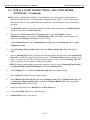
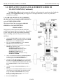
NOTE: For generator measurements, refer to Installation Data Drawing attached. For
interpretation of numbered items, refer to Parts Legend Drawing attached. Ambient
temperature around this unit must not exceed 105°F.
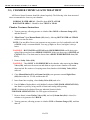
1.1) INSTALLATION INSTRUCTIONS: (CLEANER) (PORTABLE)
Set STEAM GENERATOR on level floor and attach Solution Bucket (#25) into the 2
predrilled holes on right side of generator.
CONNECTIONS:
Periodically check all plumbing and electrical connections for tightness; this should also be done
before initial start-up.
ELECTRICAL:
This generator must be connected to a disconnect switch protected by fuses or
a circuit breaker with the proper size wire by a licensed electrician in
accordance with N.E.C. and your local codes – Voltage, KW, and Phase
requirement are marked on the nameplate.
WATER SUPPLY:
Connect city water line to Y-Strainer (#6).
Purity: NOT to exceed 26,000 OHMS per CM
Temperature Range: 32°F – 140°F or 0°C – 60°C.
Pressure Range: 20PSI – 150PSI.
*CAUTION: The Pump (#8) requires clean tap water. If the water is not free of foreign matter, a 5
micron cartridge filter should be installed in the water supply line.
STEAM OUTLET:
Connect the 1/4” Union “Female End” (A) on the Steam Hose (I) from the Steam Gun to the
Steam Outlet (1/4” Union “Male End”) (#16).
SAFETY VALVE & DRAIN:
Route Safety Valve (#18) and Manual Drain (#19) separately towards the floor.
4 of 29
LB-40(C) thru LB-60(C) (Portable) - User Manual
1.2)
Electro-Steam Generator Corp.
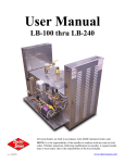
INSTALLATION INSTRUCTIONS - SOLUTION MIXER
HydroMinder Model 511 Parts
Diagram/List "OPTIONAL"
9
a
b
c
s
d
e
2
t
13
f
3
1
14
12
15
u
n
7
h
v
p
k
5
q
17
r
6
10
8
4
16
11
w
9
i
m
PART NO.
DESCRIPTION
1.
2.
3.
4.
5.
238100
506500
502000
360900
10080500
Strainer Washer
Hose Swivel
Ball Valve, 1/4"
Nipple, 1/4"
Magnet Parts Kit
-
Screw
Washer
Magnet Cover
Magnet Cap
Magnet
Magnet Spring
Magnet Yoke
5030-K
Mounting Bracket Kit (specify model 511)
a.
b.
c.
d.
e.
f.
g.
x
18
KEY
6.
h.
i.
j.
k.
m.
g
7.
n.
p.
q.
r.
8.
9.
10.
11.
12.
13.
14.
s.
t.
Hydro Systems
3798 Round Bottom Road
Cincinnati, OH 45244
Phone: (513) 271-8800
Fax: (513) 271-0160
www.hydrosystemsco.com
15.
16.
17.
u.
v.
w.
-
18.
5 of 29
x.
-
Z Bracket
U Clamp
Lock Washer (Not Shown)
Screw
Thumb Screw
665520
Valve Parts List
-
Valve Guide ("Bonnet")
Armature Spring
Armature
Diaphram
520000
505600
519000
506000
505900
506300
440121
Water Valve Body
Street Elbow, 1/4"
Nipple, 1/4" x Close
Elbow, 1/4"
Nipple, 1/4" x 6"
Vacuum Breaker
Eductor Assembly
440100
440101
Eductor Body Only
Suction Stub Only
690015
5057-A
5058-9A
Metering Tip (Kit)
Discharge Tube Assembly
Suction Tube Assembly
505809
250006
10076301
250700
Tubing, 1/2" x 9'
Ceramic Weight
Foot Valve, Viton
(Foot Valve & Weight)
5043-A
Float & Chain Assembly
507200
Bead Chain Only
LB-40(C) thru LB-60(C) (Portable) - User Manual
Electro-Steam Generator Corp.
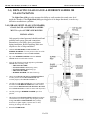
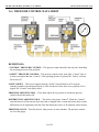
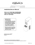
1.2) INSTALLATION INSTRUCTIONS – SOLUTION MIXER
“OPTIONAL” (Continued)
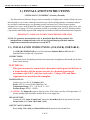
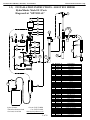
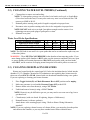
NOTE: Refer to “HydroMinder Model 511 Parts Diagram” on previous page for interpretation of
numbered & lettered items. For interpretation of numbered items with “#”, refer to Parts Legend
Drawing attached. For better understanding of installation of Solution Mixer, refer to drawing on
next page.
1.
A 4’ Red Hose should be enclosed to attach the incoming water connection to the Solution Mixer.
Attach tee end of hose to Water Inlet (#6).
2.
Remove the 2 Screws (6k) holding U-Clamp (6i) and reverse U-Clamp (6i) to where
Thumbscrews (6m) are on outside of Solution Bucket (#25). This allows Solution Mixer to fit
more vertical and Magnet Yoke (5g) moves more freely.
3.
Attach Solution Mixer on side of Solution Bucket (*25) opposite the Steam Out (*16). Tighten
Thumbscrews (6m).
4.
Attach Discharge Tube Assembly (16) to bottom of Eductor Body Only (14s). Push tight on
flange.
5.
Remove Metering Tip (15) of your choice from enclosed packet and hand screw into Suction Stub
Only (14t). (Green tip is suggested for initial start up. The Solution Mixer should be titrated, at end
of gun, or wand, with valve fully open by chemical supplier. Larger or smaller Metering Tips (15)
may be required to achieve proper working concentration.)
NOTE: For better understanding of metering tip selection, refer to section “Metering Tip Selection:”
in the HydroMinder Model 511 Manual enclosed with Solution Mixer.
6.
Attach Tubing 1/2” x 9’ (17u) to Suction Stub Only (14t). Push tight on flange.
7.
Place Viton Foot Valve (17w) into solution supply.
8.
Thread Bead Chain Only (18x) through loop on Magnetic Yoke (5g). Pull Bead Chain (18x) close
so that Float & Chain Assembly (18) is suspended in Solution Bucket (#25). If not suspended,
Solution Bucket (#25) will never fill.
9.
Attach the other end of the 4’ Red Hose to the Hose Swivel (2).
10. Verify that the Ball Valve (3) is completely open.
11. Solution Mixer is now ready for use.
6 of 29
SOLUTION
INLET
WATER INLET
(ON OPPOSITE SIDE
OF GENERATOR)
WATER &
SOLUTION
OUTLET
NEW WATER INLET
GENERATOR'S
WATER INLET
4' HOSE USED TO
CONNECT WATER INLET
OF SOLUTION MIXER TO
INCOMING WATER
CONNECTION"
1.2)
METERING TIP
4' HOSE USED TO CONNECT WATER INLET OF
SOLUTION MIXER TO INCOMING WATER CONNECTION"
LB-40(C) thru LB-60(C) (Portable) - User Manual
Electro-Steam Generator Corp.
INSTALLATION INSTRUCTIONS - SOLUTION MIXER
"OPTIONAL" (Continued)
7 of 29
LB-40(C) thru LB-60(C) (Portable) - User Manual
Electro-Steam Generator Corp.
2.) OPERATION & SEQUENCE OF EVENTS
IMPORTANT – READ INSTALLATION INSTRUCTIONS BEFORE OPERATING
START UP:
1.
Turn on water supply from the source to the generator.
2.
OPEN all valves on generator except for the Manual Drain (#19).
3.
Place Main Disconnect Box in ON position and/or Plug In.
4.
Hold in the Lever Handle (D) on the Steam Gun.
5.
Place toggle Switch (#2) in ON position.
6.
•
The Water Solenoid (#7) and Pump (#8) will engage and the chamber will begin
to fill with water. As the water level rises, it will make contact with the (G/D) and
(A) probes, indicating the heaters are safely submerged. At this time the
contactor(s) will engage, supplying power to the heaters, causing steam pressure to
accumulate.
•
The chamber will continue to fill with water until 1 second after the water makes
contact with the (C) probe, causing the Water Solenoid (#7) and Pump (#8) to turn
off.
•
If the contactor(s) still have not engaged at this time, you may need to press the
Safety Reset (#13). If your generator is required to have a Manual Low-Water
Reset (MLWR) (#3), it must be pushed it at this time to engage the contactor(s).
Once generator is full of water, release the Lever Handle (D) on the Steam Gun.
•
Steam pressure will continue to rise until is reaches 85 PSI. At this time, the
pressure control labeled “Control” will cause the contactor(s) to disengage. The
pressure will drop approximately 5-8 PSI until the “Control” causes the
contactor(s) to reengage, causing the pressure to rise again. The contactor(s) will
continue to cycle on and off during operation.
NOTE: Just because generator is up to pressure does not necessarily mean it is up to
temperature. When first starting generator, before using the gun for operation, you
should use the gun to exhaust pressure, allowing the heaters to remain on longer,
thus increasing the temperature inside the chamber and increasing its ability to
recover from loss of steam.
WARNING – Steam hose and gun will always be hot while generator is on, even when
gun is not is use.
7.
The generator is now fully operational and will produce steam until it is turned off.
8 of 29
LB-40(C) thru LB-60(C) (Portable) - User Manual
Electro-Steam Generator Corp.
2.) OPERATION & SEQUENCE OF EVENTS (Continued)
•
As steam is exhausted, the water level will drop until 3 seconds after it breaks
contact with the (C) probe. At this time, the Water Solenoid (#7) and Pump (#8)
will engage and the chamber will again fill with water. The chamber will continue
filling until 1 second after the water makes contact with the (C) probe. The Water
Solenoid (#7) and Pump (#8) will continue to cycle on and off during operation.
NOTE: If at anytime the “Control” fails and the pressure exceeds 85 PSI, the “Safety”
will cause the contactor(s) to disengage at 90 PSI and will not allow the
contactor(s) to reengage until the Safety Reset (#13) is manually pushed. If this
happens, the “Control” needs to be set lower or must be replaced. If the “Control”
and “Safety” happen to fail, and the pressure reaches 100 PSI, the Safety Valve
(#18) will pop, releasing the pressurized steam. If this happens, all three
components may need to be replaced.
STEAM GUN OPERATION:
NOTE: Refer to Steam Gun Parts Legend for interpretation of lettered items.
1.
The special Siphon Heavy Duty Steam Gun is equipped with Steam (I) and Detergent
(J) Hoses with valves for steam and detergent control.
2.
The Suction Strainer (B) at the end of the detergent hose should be placed in the
Solution Bucket (#25). Chemicals should be mixed in the bucket in proportions as
recommended by chemical supplier. (Solution Mixer “Optional”)
3.
Steam flow is obtained by pressing on the Lever Handle (D) located directly in front of
the handle. A mixture of steam and detergent is obtained by regulating the small
Detergent Valve (H) while operating the Lever Handle (D).
SHUT DOWN:
4.
To shut off generator, place Toggle Switch (#2) and Main Disconnect Box in OFF
position and/or unplug the machine. Pressure will drop naturally as the generator cools,
or generator may be drained manually through Manual Drain (#19). (See Manual Blow
Down 3.1)
WARNING – HOT WATER and STEAM under HIGH PRESSURE can lift drain pipes
right off the ground and cause SERIOUS INJURY. Make sure drain pipe is SECURE
and CANNOT move. The drain must be directed into a HIGH TEMPERATURE drain
(NO PVC).
9 of 29
LB-40(C) thru LB-60(C) (Portable) - User Manual
Electro-Steam Generator Corp.
3.) CLEANING & MAINTENANCE
The following cleaning procedures are HIGHLY RECOMMENDED in order to keep your
Steam Generator in the best operating condition at all times.
3.1) MANUAL “BLOW DOWN”
A Manual “Blow Down” is an easy way to GREATLY extend the life of your Steam
Generator. The following is the LEAST amount of times recommended to blow down your
generator:
NORMAL WATER AREAS – Should be done ONCE A WEEK.
BAD WATER AREAS – Should be done ONCE A DAY.
NOTE: The best time to Blow Down your generator is after it has been running for some time,
while it is still hot.
1.
Place Toggle Switch (#2) and Main Disconnect Box in OFF position and/or unplug the
machine.
2.
Allow pressure to drop between 10 and 20 PSI.
3.
Open Manual Drain (#19) slowly, allowing HOT WATER and STEAM to blow out
into the drain, cleaning out the generator.
NOTE: Blow Down your generator at any pressure you feel comfortable with. 10 to 20 PSI is
only a recommendation. You may go higher or lower, but higher is always better.
WARNING – HOT WATER and STEAM under HIGH PRESSURE can lift drain pipes right
off the ground and cause SERIOUS INJURY. Make sure drain pipe is SECURE and
CANNOT move. The drain must be directed into a HIGH TEMPERATURE drain (NO
PVC) or outside.
3.2) CLEANING WATER LEVEL PROBES
Water Level Probes are the heart of your generator. Almost all steam generator malfunctions
are caused by dirty water level probes. CLEANING your PROBES is by far the MOST
IMPORTANT maintenance step to keep your generator running properly. The following is the
LEAST amount of times recommended to clean your probes:
NORMAL WATER AREAS – Should be done TWICE A YEAR.
BAD WATER AREAS – Should be done 3-4 TIMES A YEAR.
NOTE: The best time to clean your probes is before you turn your generator on, while it is still
cool.
1.
Place Toggle Switch (#2) and Main Disconnect Box in OFF position and/or unplug the
machine.
2.
Make sure generator is cool and the Pressure Gauge (#15) reads 0 PSI.
3.
Locate the blue box on top of generator and remove cover plate, exposing the Water
Level Probes (#5).
4.
Use 5/16” Socket to remove wires from probes.
5.
Use 13/16” Spark Plug Socket to remove probes from chamber.
10 of 29
LB-40(C) thru LB-60(C) (Portable) - User Manual
Electro-Steam Generator Corp.
3.2) CLEANING WATER LEVEL PROBES (Continued)
6.
7.
8.
9.
Clean probes to remove rust and scaling.
NOTE: To clean probes you may use wire wheel, wire brush, steal wool, or Scotch-Brite.
(Wire wheel works the best) You may also want to try some sort of chemical like CLR
remover or LIME-A-WAY.
Reinstall probes assuring each probe’s length is assigned to its proper letter.
Reconnect wires to probes assuring each color is also assigned to its proper letter.
NOTE: DO NOT make wires too tight. Just tighten enough to make contact. Over
tightening can cause probe plugs to pull apart over time.
Reinstall cover plate.
Water Level Probe Specifications:
Letter Assignment on Chamber
Water Level Probe Length
Wire Color Assignment
Assignment on Dual Function Board
A
15”
RED
LLCO
B
C
D/G
15 3/8”
13”
15 3/8”
Not Used BLACK GREEN
Not Used
H
G
NOTE: The (B) Probe is not used. It is a spare probe that can be cut and used to replace any one
of the other probes.
WARNING – There MUST be NO PRESSURE in the chamber when removing probes. If you
must change probes while chamber is HOT, make sure the steam out and drain valves are open
to assure chamber will remain depressurized. DO NOT touch probes with your bare hands
while HOT, and be cautious of escaping steam from probe holes while probes are removed.
3.3) CLEANING OR REPLACING HEATERS
Heaters are located inside the control panel (#1) below the insulation barrier, bolted into the
chamber. If (3.5) Chamber Chemical/Acid Treatments are not regularly done, heaters must be
taken out at least ONCE A YEAR, cleaned with wire brush and reinstalled using a new gasket.
If you are replacing or cleaning your heater elements:
1.
Place Toggle Switch (#2) and Main Disconnect Box in OFF position and/or unplug.
2.
Make sure generator is cool and the Pressure Gauge (#15) reads 0 PSI.
3.
Remove heater wires from heater(s), using a 3/8” Socket.
4.
Unbolt and remove heater(s) using a 1 1/16” Socket.
NOTE: Heater(s) may be difficult to get out; you may need to use some sort of pry bar to
get them loose.
5.
Clean heater(s) with wire brush. If replacing, dispose of old heater(s).
6.
Reinstall heater(s) with new gasket(s).
7.
Attach heater wires assuring proper wiring. *Refer to Heater Wiring Schematics
attached*
NOTE: If you are replacing a heater because of a heater failure, you must also clean the probes
and clean out the chamber, or you may have another heater failure within 48 hours.
11 of 29
LB-40(C) thru LB-60(C) (Portable) - User Manual
Electro-Steam Generator Corp.
3.4) REPLACING GLASS GAUGE & RUBBER WASHERS OR
GLASS PACKINGS
The Sight Glass (#10) gives the operator the ability to easily monitor the actual water level
inside the chamber. If the Sight Glass (#10) gets clogged or is no longer functional, it can be very
difficult to troubleshoot a problem.
3.4.1) BRASS SIGHT GLASS (STANDARD)
GLASS GAUGE and RUBBER WASHERS
MUST be replaced EVERY SIX MONTHS
INSTALLATION:
Only properly trained personnel should install and
maintain water gauge glass and connections.
Remember to wear safety gloves and glasses
during installation. Before installing, make sure
all parts are free of chips and debris.
1.
Uninstall GUARD RODS, GLASS GAUGE, and
RUBBER WASHERS. (You may need to rotate one of the
GAUGE FITTINGS to remove GLASS GAUGE)
2.
Slip a new RUBBER WASHER on the new GLASS
GAUGE about an inch from the bottom.
3.
Now slip the following items through the top of GLASS
GAUGE in the following order:
• FRICTION WASHER
• GLASS PACKING NUT (facing down)
• GLASS PACKING NUT (facing up)
• FRICTION WASHER
• RUBBER WASHER (inch down from top)
4.
Gently insert GLASS GAUGE into GAUGE FITTINGS.
You may need to rotate GAUGE FITTINGS until
vertically aligned, after GLASS GAUGE is in.
5.
Carefully raise GLASS GAUGE about 1/16” from bottom
and slide lower RUBBER WASHER down until it makes
contact with the BOTTOM GAUGE FITTING. (DO NOT
allow GLASS GAUGE to remain in contact with any metal)
6.
Carefully slide upper RUBBER WASHER up as far as
possible.
7.
Hand tighten both GLASS PACKING NUTS, then tighten
1/2 turn more by wrench. Tighten only enough to prevent
leakage. DO NOT OVER TIGHTEN! If any leakage
should occur, tighten slightly, a quarter turn at a time,
checking for leakage after each turn.
8.
Reinstall GUARD RODS.
12 of 29
LB-40(C) thru LB-60(C) (Portable) - User Manual
Electro-Steam Generator Corp.
3.4) REPLACING GLASS GAUGE & RUBBER WASHERS OR
GLASS PACKINGS (Continued)
The Sight Glass (#10) gives the operator the ability to easily monitor the actual water level inside the
chamber. If the Sight Glass (#10) gets clogged or is no longer functional, it can be very difficult to
troubleshoot a problem.
3.4.2) BRASS SIGHT GLASS (SEISMIC)
GLASS GAUGE and GLASS PACKINGS MUST be
replaced EVERY SIX MONTHS
The Seismic Sight Glass is equipped with BALL
CHECKS in each GAUGE FITTING.
INSTALLATION:
Only properly trained personnel should install and
maintain water gauge glass and connections. Remember
to wear safety gloves and glasses during installation.
Before installing, make sure all parts are free of chips
and debris.
1.
Uninstall GUARD RODS, GLASS GAUGE, and GLASS
PACKINGS. (You may need to rotate one of the GAUGE
FITTINGS to remove GLASS GAUGE)
2.
Slip a new GLASS PACKINGS on the new GLASS
GAUGE about an inch from the bottom.
3.
Now slip the following items through the top of GLASS
GAUGE in the following order:
• PACKING GLAND (facing down)
• GLASS PACKING NUT (facing down)
• GLASS PACKING NUT (facing up)
• PACKING GLAND (facing up)
• GLASS PACKINGS (inch down from top)
• PACKING WASHER
4.
Gently insert GLASS GAUGE into GAUGE FITTINGS.
You may need to rotate GAUGE FITTINGS until
vertically aligned, after GLASS GAUGE is in.
5.
Carefully raise GLASS GAUGE about 1/16” from bottom
and slide lower GLASS PACKINGS down until it makes
contact with the BOTTOM GAUGE FITTING. (DO NOT
allow GLASS GAUGE to remain in contact with any
metal)
6.
Carefully slide upper GLASS PACKINGS up as far as
possible.
7.
Hand tighten both GLASS PACKING NUTS, then tighten
1/2 turn more by wrench. Tighten only enough to prevent
leakage. DO NOT OVER TIGHTEN! If any leakage
should occur, tighten slightly, a quarter turn at a time,
checking for leakage after each turn.
8.
Reinstall GUARD RODS.
13 of 29
LB-40(C) thru LB-60(C) (Portable) - User Manual
Electro-Steam Generator Corp.
3.5) CHAMBER CHEMICAL/ACID TREATMENT
All Electric Steam Generator should be cleaned regularly. The following is the least amount of
times recommended to clean out your chamber:
NORMAL WATER AREAS – Should be done ONCE A YEAR.
BAD WATER AREAS – Should be done TWICE A YEAR.
Chamber Treatment Instructions:
1. Turn on generator, allowing pressure to climb to 10 to 20 PSI on Pressure Gauge (#15),
and then shut off.
2. “Blow Down” Open Manual Drain (#19) slowly, allowing HOT WATER and STEAM
to blow out into the drain.
NOTE: You may Blow Down your generator at any pressure you feel comfortable with. 10
to 20 PSI is only a recommendation. You may go higher or lower, but higher is always
better.
WARNING – HOT WATER and STEAM under HIGH PRESSURE can lift drain pipes
right off the ground and cause SERIOUS INJURY. Make sure drain pipe is SECURE and
CANNOT move. The drain must be directed into a HIGH TEMPERATURE drain (NO
PVC).
3. Remove Safety Valve (#18).
WARNING – There MUST be NO PRESSURE in the chamber when removing the Safety
Valve (#18), make sure the steam out and drain are open to assure chamber will remain
depressurized. Be cautious of escaping steam from chamber while Safety Valve (#18) is
removed.
4. Close Manual Drain (#19) and Steam Out (#16); turn generator on until Sight Glass
(#10) shows that it is 1/2 full, and then shut off.
5. Insert funnel into coupling, where Safety Valve (#18) used to be.
6. Pour 1 Gallon of hydrochloric acid (inhibited) solution (NON-FOOD APPLICATIONS)
into funnel very slowly, being careful of fumes and venting while pouring.
NOTE: Solution can be obtained from any industrial chemical dealer.
FOR FOOD APPLICATIONS: Use FDA approved chemicals.
7. Remove funnel, reinstall Safety Valve (#18), and verify Steam Out (#16) is closed; let
solution set in generator for 1 HOUR.
8. Turn on generator, allowing pressure to climb to 5 PSI on Pressure Gauge (#15), and then
shut off.
14 of 29
LB-40(C) thru LB-60(C) (Portable) - User Manual
Electro-Steam Generator Corp.
3.5) CHAMBER CHEMICAL/ACID TREATMENT (Continued)
9. Allow the pressure to drop to 0 PSI on Pressure Gauge (#15) naturally. DO NOT open
Steam Out (#16) or Manual Drain (#19) until pressure is down.
10.
Remove Safety Valve (#18).
11.
Reinsert funnel, and fill generator completely to the top with clean water; let stand for an
additional 1/2 HOUR.
NOTE: Turning on the generator will not completely fill it to the top. Filling must be done
manually through the safety valve coupling.
12.
Open Manual Drain (#19) to drain generator.
13.
Close Manual Drain (#19); refill generator completely to the top with clean water and
open Manual Drain (#19) to flush out generator completely.
14.
Reinstall Safety Valve (#18) and close Manual Drain (#19).
15.
Turn on generator, allowing pressure to climb to 10 to 20 PSI on Pressure Gauge (#15),
and then shut off.
16.
“Blow Down” Open Manual Drain (#19) slowly, allowing HOT WATER and STEAM
to blow out into the drain.
NOTE: You may Blow Down your generator at any pressure you feel comfortable with. 10
to 20 PSI is only a recommendation. You may go higher or lower, but higher is always
better.
WARNING – HOT WATER and STEAM under HIGH PRESSURE can lift drain pipes
right off the ground and cause SERIOUS INJURY. Make sure drain pipe is SECURE and
CANNOT move. The drain must be directed into a HIGH TEMPERATURE drain (NO
PVC).
17.
Your generator is now ready for normal use and operation.
15 of 29
LB-40(C) thru LB-60(C) (Portable) - User Manual
Electro-Steam Generator Corp.
3.6) PRESSURE CONTROL DATA SHEET
DEFINITIONS:
“CONTROL” PRESSURE CONTROL – This pressure control should be the only one controlling
the operating pressure of the generator.
“SAFETY” PRESSURE CONTROL – This pressure control is only used if the “Control” fails. It
is always set higher than the “Control”; if the operating pressure is passed, The “Safety” will turn
the heaters off.
SAFETY RESET – This reset is tripped when the “Safety” turns the heaters off. It must be
manually pushed to turn the heaters back on. This lets the user know there was a problem. If it is
tripped, the “Control” most likely failed.
PRESSURE ADJUSTING DIAL – These dials adjust the set pressure at which each pressure
control will turn the heaters off.
DIFFERENTIAL ADJUSTING DIAL – This dial is only on the “Control”. When the “Control”
turns the heaters off, the amount of pressure that is dropped before it turns the heaters back on (the
differential) can be adjusted by this dial. This dial should never have to be adjusted, unless desired.
PRESSURE GAUGE – This tells the user what pressure is in the chamber. The pressure controls
are set to this gauge.
16 of 29
LB-40(C) thru LB-60(C) (Portable) - User Manual
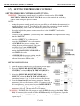
3.7)
Electro-Steam Generator Corp.
SETTING THE PRESSURE CONTROLS
SETTING PRESSURE CONTROLS INSTUCTIONS:
WARNING – The pressure controls must be set while all circuits are live. TO AVOID
ELECTRICAL SHOCK, DO NOT TOUCH the wires or the terminals in which they
connect while setting the pressure controls.
NOTES:
-
Setting the pressure controls greatly relies on your ability to tell whether the contactor(s) are
turning the heaters on or off. You should be able to hear the contactor(s), located inside the
Control Box (#1), click on and off. Familiarize yourself with this sound.
-
The order in which the pressure controls must be set is the “SAFETY” and then the
“CONTROL”.
-
In order to set the “SAFETY” you must keep the “CONTROL” at a higher pressure setting
than the “SAFETY”
-
Once the “SAFETY” is set, then you can
lower the “CONTROL” to its correct setting.
-
To INCREASE the pressure setting, when
looking down on pressure control, using your
two index fingers, turn the PRESSURE
ADJUSTMENT DIAL CLOCKWISE,
causing the BLACK INDICATOR LINE to
move DOWN the scale.
-
To DECREASE the pressure setting, turn the
dial COUNTER CLOCKWISE, causing the
indicator line to move UP the scale.
SETTING INSTRUCTIONS:
1. Open the pressure control covers, as shown on previous page.
2. Adjust the PRESSURE ADJUSTMENT DIAL on the
“CONTROL” so that the BLACK INDICATOR LINE is
somewhere between ½ and ¾ of the way down from the top.
3. Adjust the PRESSURE ADJUSTMENT DIAL on the
“SAFETY” so that the BLACK INDICATOR LINE is
somewhere between ¼ and ½ of the way down from the top.
4. Close the Steam Out (#16) and turn on generator. When the
contactor(s) click on, the pressure will rise. If contactor(s) do not
click on right away, you may need to press SAFETY RESET.
Continue to watch the Pressure Gauge (#15) until you hear the
contactor(s) click off. This may take up to 20 minutes.
WARNING – DO NOT allow the pressure to reach 100 PSI, the rating on the Safety Valve
(#18). If contactor(s) do not turn off before 95 PSI, manually shut off generator, open the
Steam Out (#16), and DECREASE the pressure setting on the “SAFETY” pressure control.
Repeat step #4.
17 of 29
LB-40(C) thru LB-60(C) (Portable) - User Manual
Electro-Steam Generator Corp.
3.7) SETTING THE PRESSURE CONTROLS (Continued)
5. At this point the contactor(s) should be clicked off and you should be able to click them on
and then off again by pressing the SAFETY RESET. This is a way to test if the “SAFETY”
is still controlling the pressure, and not the “CONTROL”. While setting the “SAFETY” and
the contactor(s) are off, if the SAFETY RESET does not cause the contactor(s) to click on
and off again, INCREASE the setting on the “CONTROL”
WARNING – DO NOT allow the pressure to exceed 100 PSI. If contactor(s) do not turn off
before 95 PSI, manually shut off
generator, open the Steam Out (#16), and
Pressure Control Settings
DECREASE the pressure setting on the
“Control”
“Safety”
“SAFETY” pressure control. If you
Cleaner
cannot get the “SAFETY” to control the
85 PSI
90 PSI
(0-100 PSI)
pressure, it may need to be replaced.
6. Open the Steam Out (#16) to exhaust some pressure. Continue pressing the SAFETY
RESET until the contactor(s) click on and remain on. The pressure should eventually begin
to rise. If it doesn’t, throttle the Steam Out (#16) somewhere between closed and open until
it does.
7. Pay attention to what the pressure reads when the contactor(s) click off. If the pressure
stopped BELOW 90 PSI, then INCREASE the pressure setting on the “SAFETY”. If the
pressure stopped ABOVE 90 PSI, then DECREASE the pressure setting.
8. Continue to watch the pressure go up and down, while adjusting the “SAFETY” and
pressing the SAFETY RESET, until the pressure stops at 90 PSI.
9. At this point the “SAFETY” should be set at 90 PSI, and the “CONTROL” should be set
somewhere above 90 PSI.
10. Let the pressure drop below 85 PSI and then press the SAFETY RESET, so that the
contactor(s) click on. DECREASE the pressure setting on the “CONTROL” until the
contactor(s) click off.
11. Repeat Step 10 until you no longer need to press the SAFETY RESET for the contactor(s)
to click on.
12. Continue to watch the pressure go up and down, while adjusting the “CONTROL”, until the
pressure stops at 85 PSI.
13. The Pressure Controls are now set.
NOTE: If at anytime the SAFETY RESET needs to be pressed after the pressure controls are
set, either one of the controls are bad, the “SAFETY” is set too low, or the “CONTROL” is
set too high.
18 of 29
LB-40(C) thru LB-60(C) (Portable) - User Manual
Electro-Steam Generator Corp.
4.) CALCULATIONS AND DATA SHEETS
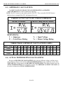
4.1) HEATER POWER & VOLTAGE RATINGS
LB 40-60 Model units use 2 Heaters to meet the required (KW) POWER from the
customer’s specified INPUT VOLTAGE. Each heater comes in 3 different (KW) POWER
RATINGS and 4 different VOLTAGE RATINGS.
NOTE: SINGLE PHASE is NOT usually OFFERED for 40KW+ generators, because of
the extra cost to run and build with the higher amp draw requirements. Although not offered, in
some special cases single phase 40KW+ generators can be made.
AVAILABLE HEATER RATINGS
KW
20
25
30
POWER RATINGS per MODEL
VOLTAGES
208
230
480
600
208
230
480
600
208
230
480
600
MODEL UNIT
LB-40
LB-50
LB-60
QUAN.
KW
2
20
2
25
2
30
HEATER VOLTAGE RATINGS per INPUT VOLTAGE (VOLTS)
Input Voltage 208 220 230
208 230 230
LB-40
208 230 230
LB-50
208 230 230
LB-60
240 380 400 415 425 440 460 480 550 575 600
230
208
240
240
240
480
480
480
600
600
600
230
208
230
230
230
480
480
480
600
600
600
230
208
230
230
230
480
480
480
600
600
600
NOTE: 380-425V heaters are not usually rated for 380-425V. They are usually 208-240V heaters
that have been re-stamped 380-425V and jumpered in series.
4.2) TOTAL POWER RATING CALCULATIONS
The HEATER POWER RATING and NUMBER OF HEATERS are used to calculate the
TOTAL POWER RATING. Since the HEATER POWER RATINGS are in Kilowatts, they
must be multiplied by 1000 to convert them to Watts.
DEFINITIONS:
PT = Total Power Rating
PH = Heater Power Rating
xH = Number of Heaters
MODEL UNIT
LB-40
LB-50
LB-60
Heater Power Rating (Watts)
X Number of Heaters
Total Power Rating (Watts)
20,000
2
40,000
25,000
2
50,000
30,000
2
60,000
19 of 29
LB-40(C) thru LB-60(C) (Portable) - User Manual
Electro-Steam Generator Corp.
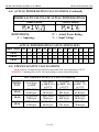
4.3) AMPERAGE CALCULATIONS
The INPUT VOLTAGE, PHASE, TOTAL POWER RATING, and HEATER
VOLTAGE RATING are used to calculate the amperage.
NOTE: 380-425V heaters are not usually rated for 380-425V. They are usually 208-240V heaters
that have been re-stamped 380-425V and jumpered in series.
FORMULAS TO CALCULATE 3 PHASE AMPERAGE
208-240V & 440-600V
380-415V (using 208-240V heaters)
DEFINITIONS:
I = Amperage
PT = Total Power Rating
VI = Input Voltage
VH = Heater Voltage Rating
THREE PHASE AMP DRAW CALCULATIONS (AMPS)
Input Voltage 208 220 230 240 380 400 415 425 440 460 480 550 575 600
LB-40
111
96
100
105
67.6 58.2 60.4 61.8 44.1 46.1 48.1 35.3 36.9 38.5
LB-50
139
120
126
131
84.5 72.8 75.5 77.3 55.1 57.6 60.1 44.1 46.1 48.1
LB-60
167
144
151
157
101
87.3 90.6 92.8 66.2 69.2 72.2 52.9 55.3 57.7
4.4) ACTUAL POWER RATING CALCULATIONS
Because the HEATER VOLTAGE RATINGS only come in 4 different voltages, and there are so
many different voltages in the field, the TOTAL POWER RATING is only completely accurate if the
VOLTAGE IN is exactly equal to the HEATER VOLTAGE RATING. This means, in most cases, the
TOTAL POWER RATING is not completely accurate. The AMERAGE and INPUT VOLTAGE can
be used to calculate the ACTUAL POWER RATING.
20 of 29
LB-40(C) thru LB-60(C) (Portable) - User Manual
Electro-Steam Generator Corp.
4.4) ACTUAL POWER RATING CALCULATIONS (Continued)
FORMULAS TO CALCULATE ACTUAL POWER RATINGS
THREE PHASE
DEFINITIONS:
I = Amperage
SINGLE PHASE
PA = Actual Power Rating
VI = Input Voltage
ACTUAL POWER RATING CALCULATIONS (KW)
Input Voltage 208 220 230 240 380 400 415 425 440 460 480 550 575 600
LB-40
40
36.6
40
43.6 44.5 40.3 43.4 45.5 33.6 36.7
40
LB-50
50
45.7
50
54.4 55.6 50.4 54.3 56.9
45.9
50
LB-60
60
54.9
60
65.3 66.8 60.5 65.1 68.3 50.4 55.1
60
42
33.6 36.7
42
45.9
50
50.4 55.1
60
4.5) STEAM CAPACITY CALCULATIONS
Steam Capacity Calculations are based on the impossible feed water temperature of 212°F.
WARNING – Anything above 140°F will cause damage to water solenoid and pump.
NET STEAM CAPACITY CALCULATIONS
MODEL
UNIT
LB-40
LB-50
LB-60
Feed Water
@ 212°F
138.0 LB/hr
62.6 Kg/hr
173.0 LB/hr
78.5 Kg/hr
207.0 LB/hr
93.9 Kg/hr
Feed Water
@ 140°F, 90%
of 212°F
124.2 LB/hr
56.3 Kg/hr
155.7 LB/hr
70.6 Kg/hr
186.3 LB/hr
84.5 Kg/hr
21 of 29
Feed Water
@ 100°F, 80%
of 212°F
110.4 LB/hr
50.1 Kg/hr
138.4 LB/hr
62.8 Kg/hr
165.6 LB/hr
75.1 Kg/hr
40
Feed Water
@ 60°F, 75%
of 212°F
103.5 LB/hr
47.0 Kg/hr
129.8 LB/hr
58.9 Kg/hr
155.3 LB/hr
70.4 Kg/hr
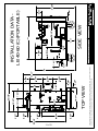
6
2
10
23
5
11
24
18
22
23
TOP VIEW
17
19
16
25
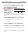
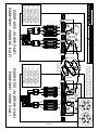
1.)
2.)
3.)
4.)
5.)
6.)
7.)
8.)
9.)
10.)
11.)
1
23
19
24
DRAWING TITLE:
6
3
17
7
4
18
CONTROL
CHRISTOPHER FERRARA
SAL NEGRO
CHECKED:
ENGINEER:
APPROVED:
HIGH PRESSURE
CLEANER
PORTABLE
CHRISTOPHER FERRARA
DRAWN BY:
SAFETY
8
23
311-040-060-000306
14
15
2
SHEET: 1 OF 1
SCALE: N/A
1
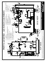
Manual Drain - 1" Ball Valve
1 KVA Transformer
8" Caster Wheels
Handle
Solution Bucket
13
19.)
22.)
23.)
24.)
25.)
DWG NO.:
01-05-10
01-05-10
01-05-10
LB 40-60
11
DECRIPTIONS:
MODEL UNIT:
9
5
12
0-90 PSI Pressure Controls
Reset on "Safety" Pressure Switch
1/4" Needle Valve
0-160 PSI Pressure Gauge
Steam Out - 1/4" Union (Male End)
1/2" Vacuum Relief Valve
Safety Relief Valve
SIDE VIEW
10
16
12.)
13.)
14.)
15.)
16.)
17.)
18.)
(PARTS LEGEND) LB 40-60 (C)(PORT)
11
Control Box
ON/OFF Switch
Manual Low-Water Reset (MLWR) (Optional)
Dual Function Board w/ Enclosure
Water Level Probes
Water Inlet - 1/2" Y-Strainer
1/2" Water Solenoid
1/3 HP Pump & Motor
1/2" Check Valves
5/8" x 8" Sight Glass (Seismic Optional)
Water Barrier - 1/2" U-Tube
PARTS LEGEND - LB 40-60 (CLEANER)
This drawing and all information therein are the property of Electro-Steam Generator Corp. and shall not be disclosed,
in whole or in part, to any third party without prior permission of Electro-Steam Generator Corp.
22 of 29
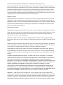
O
D
C1
E
U
K
X
C2
S
L
I
N
T2
H
T1
J
W
K
L
V
M
N
R3 R2 R4
B
A
0018058
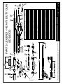
SUCTION STRAINER
B
0014027
0014007
0014064
STANDARD NOZZLE
FLARE NOZZLE
1/4" SOLUTION VALVE
10' STEAM HOSE
10' DETERGENT HOSE
F
G
H
I
J
0018001
0018024
TUBE NUT
NOZZLE CONNECTOR
BASE CASTING
PERFORATED SHIELD
SHIELD SCREWS
HANDLE SCREW
COPPER GASKET
1/4" X 1 1/2" NIPPLE
1/2" X 1 1/2" NIPPLE
R4
R5
S
T1
T2
U
V
W
X
DRAWING TITLE:
0014057
RUBBER "O" RING
R3
CHRISTOPHER FERRARA
SAL NEGRO
CHRISTOPHER FERRARA
JOHN PARDINI
DRAWN BY:
CHECKED:
ENGINEER:
APPROVED:
-
MODEL UNIT:
14
12
5
09-19-07
09-20-07
09-19-07 DWG NO.:
09-20-07
-
-
-
-
17
-
-
0014001
NOT SOLD SEPARATELY
NOT SOLD SEPARATELY
-
NOT SOLD SEPARATELY
NOT SOLD SEPARATELY
INCLUDES "P1, R1, R2, R3, R4, & R5
-
INCLUDES "Q2"
-
NOT SOLD SEPARATELY
INCLUDES "P2 & P3"
-
-
-
-
-
-
-
-
(OPTIONAL) NOT STANDARD
-
INCLUDES "D"
-
-
INCLUDES "C2"
TO SOLUTION BUCKET (#25)
19
-
NOTES:
R5
CONNECTS TO STEAM OUT (#16)
R1
Q1
3
4
7E
7C
6
7B
7A
7
10
9
18
7D
-
DECRIPTIONS:
PARTS LEGEND - HEAVY DUTY GUN
-
-
-
-
-
-
0013990
-
-
OUTER TUBE
TUBE SLEEVE
R1
0014037
-
0014036
-
-
R2
INNER TUBE JACKET
OUTER TUBE ASSEMBLY
R
INNER TUBE
Q1
Q2
GRIP SPACER
0014063
GRIP
P1
DRIVE SCREWS
0014011
1/2" X 1/2" HOSE BARB
O
P3
8
0014023
1/4" X 1/4" HOSE BARB
N
P2
-
0014030
1/2" X 1/4" HOSE BARB
M
-
0014060
-
-
-
-
13
1/4" HOSE CLAMP
0014012
0014010
0014009
15
15A
L
1/2" HOSE CLAMP
-
0014022
1/2" WHISTLE VALVE
E
K
11
-
LEVER HANDLE
1
2
D
-
0014055
REAR HANDLE
REAR HANDLE INSULATOR
C1
-
-
OAKITE DRW"D-797" PART #
P3
C2
0014041
ELECTRO-STEAM
PART NUMBER
DESCRIPTION
1/4" UNION (FEMALE END)
A
REF.
P1
P2
P3
Q2
G
SHEET: 1 OF 1
SCALE: N/A
F
PARTS LEGEND - HEAVY DUTY GUN
(0014001)
This drawing and all information therein are the property of Electro-Steam Generator Corp. and shall not be disclosed,
in whole or in part, to any third party without prior permission of Electro-Steam Generator Corp.
23 of 29
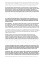
CONTROL
TOP VIEW
This drawing and all information therein are the property of Electro-Steam Generator Corp. and shall not be disclosed,
in whole or in part, to any third party without prior permission of Electro-Steam Generator Corp.
24 of 29
S AFETY
CHRISTOPHER FERRARA
SAL NEGRO
CHECKED:
ENGINEER:
APPROVED:
DWG NO.:
01-05-10
01-05-10
01-05-10
LB 40-60
HIGH PRESSURE
CLEANER
PORTABLE
MODEL UNIT:
CHRISTOPHER FERRARA
DRAWN BY:
DECRIPTIONS:
(INSTALLATION DATA) LB 40-60 (C)(PORT)
DRAWING TITLE:
SAFETY
SIDE VIEW
CONTROL
411-040-060-000306
INSTALLATION DATA LB 40-60 (C)(PORTABLE)
SHEET: 1 OF 1
SCALE: N/A
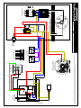
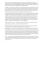
NC
NC
COM
COM
RESET
G
YEL
RED
BLK
RED
GRN
WATER SOLENOID
YEL
BLK
H
LLCO
RED
PC BOARD
BLUE
L
G
L2
NO
25 of 29
C
1/3HP PUMP & MOTOR
HIGH PRESSURE ONLY
C B
A G
WATER LEVEL
PROBES
NO
G
A
BLUE
RED
BLK
PRL
YEL
RED
YEL
NC
BLK
RED
CHRISTOPHER FERRARA
SAL NEGRO
CHECKED:
ENGINEER:
APPROVED:
BLUE
YEL
DWG NO.:
12-30-09
12-30-09
12-30-09
LB 10-240
120V
MOTOR
RELAY
CHRISTOPHER FERRARA
MODEL UNIT:
YEL
120V IN
RED
HIGH PRESSURE
-
YEL
RED
YEL
RED
DRAWN BY:
LB (H)
BLUE
BLUE
ON/OFF
TOGGLE
SWITCH
DECRIPTIONS:
NC
DRAWING TITLE:
C
NO
C
DUAL PRESSURE
CONTROLS
B
PROBE LENGTHS
This drawing and all information therein are the property of Electro-Steam Generator Corp. and shall not be disclosed,
in whole or in part, to any third party without prior permission of Electro-Steam Generator Corp.
BLK
NO
BLK
BLK
BLK
OPTIONAL
MANUAL LOWWATER RESET
L1
L2
L3
T2
T3
SHEET: 1 OF 1
SCALE: N/A
GRND
111-010-240-111200
T1
CONTACTOR
L1
HIGH VOLTAGE IN
208-600V
L2
T2
L1
T1
T3
L3
T1
L1
T2
L2
T3
L3
T1
L1
(3PH) 40-60KW
(208-240V)
T2
L2
T3
L3
.
.
.
T1
L1
T2
L2
T3
L3
T2
T1
T3
L3
T1
L1
T2
L2
T3
L3
T1
L1
T2
L2
T3
L3
-
CHRISTOPHER FERRARA
SAL NEGRO
T1
L1
T2
L2
T3
L3
DWG NO.:
12-30-09
12-30-09
12-30-09
LB 40-60
T3
L3
CHRISTOPHER FERRARA
ENGINEER:
CHECKED:
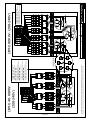
THREE PHASE HEATER WIRING
40-80KW 208-240V
-
T2
L2
MODEL UNIT:
T1
L1
APPROVED:
DRAWN BY:
DECRIPTIONS:
(HEATERS) LB 40-60 (3PH)(208-240V)
L2
L1
T1
L1
-
T2
L2
T3
L3
SHEET: 1 OF 1
SCALE: N/A
(1) 13064 - 200 AMP TERMINAL BLOCK
(6) 26137 - 50AMP 3POLE CIRCUIT BREAKERS
(6) 13069 - 75AMP CONTACTORS
(3) 10079 or 10025 - 25KW 208 or 230V HEATERS
(3PH) 80KW - (208-240V)
DRAWING TITLE:
HEATER COILS MUST GO
FROM TOP TO BOTTOM.
(12) 13046 - 60AMP 250V CLS-RK5 FUSES
(2) 10028 or 10029 - 30KW 208 or 230V HEATERS
(3PH) 60KW - (208-240V)
(12) 13044 - 50AMP 250V CLS-RK5 FUSES
(2) 10079 or 10025 - 25KW 208 or 230V HEATERS
(3PH) 50KW - (208-240V)
(12) 13013 - 40AMP 250V CLS-RK5 FUSES
(2) 10022 or 10023 - 20KW 208 or 230V HEATERS
(3PH) 40KW - (208-240V)
(1) 13064 - 200 AMP TERMINAL BLOCKS
(4) 13069 - 75AMP CONTACTORS
(4) 13056 - 60AMP 250V FUSE BLOCKS
This drawing and all information therein are the property of Electro-Steam Generator Corp. and shall not be
disclosed, in whole or in part, to any third party without prior permission of Electro-Steam Generator Corp.
26 of 29
L2
T2
L1
T1
L1
T1
L3
T3
T2
L2
T3
L3
.
.
.
.
.
HEATER COILS MUST GO
FROM TOP TO BOTTOM.
T2
L2
T3
L3
SAL NEGRO
CHRISTOPHER FERRARA
ENGINEER:
CHECKED:
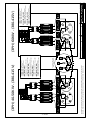
THREE PHASE HEATER WIRING
40-60KW 380-415V
-
T3
L3
.
DWG NO.:
12-30-09
12-30-09
12-30-09
-
SHEET: 1 OF 1
SCALE: N/A
(6) 13047 - 60AMP 600V CLS-RK5 FUSES
(2) 10029 - 30KW 230V HEATERS *stamped 400V
(3PH) 60KW - (400-415V)
LB 40-60
T2
L2
CHRISTOPHER FERRARA
MODEL UNIT:
T1
L1
APPROVED:
DRAWN BY:
(HEATERS) LB 40-60 (3PH)(380-415V)
T1
L1
.
(6) 13047 - 60AMP 600V CLS-RK5 FUSES
(2) 10028 - 30KW 208V HEATERS *stamped 380V
(3PH) 60KW - (380-400V)
(1) 13064 - 200 AMP TERMINAL BLOCKS
(2) 13069 - 75AMP CONTACTORS
(2) 13056A - 60AMP 600V FUSE BLOCKS
(3PH) 60KW - (380-415V)
DECRIPTIONS:
DRAWING TITLE:
(6) 13045 - 50AMP 600V CLS-RK5 FUSES
(2) 10025 - 25KW 230V HEATERS *stamped 400V
(3PH) 50KW - (400-415V)
(6) 13045 - 50AMP 600V CLS-RK5 FUSES
(2) 10079 - 25KW 208V HEATERS *stamped 380V
(3PH) 50KW - (380V)
(6) 13013A - 40AMP 600V CLS-RK5 FUSES
(2) 10023 - 20KW 230V HEATERS *stamped 400V
(3PH) 40KW - (400-415V)
(6) 13013A - 40AMP 600V CLS-RK5 FUSES
(2) 10022 - 20KW 208V HEATERS *stamped 380V
(3PH) 40KW - (380V)
(1) 13061 - 100 AMP TERMINAL BLOCKS
(2) 13069 - 75AMP CONTACTORS
(2) 13056A - 60AMP 600V FUSE BLOCKS
(3PH) 40-50KW - (380-415V)
This drawing and all information therein are the property of Electro-Steam Generator Corp. and shall not be
disclosed, in whole or in part, to any third party without prior permission of Electro-Steam Generator Corp.
27 of 29
L2
T2
L1
T1
T3
L3
T2
L2
T3
L3
T2
L2
T3
L3
SAL NEGRO
T3
L3
.
.
-
SHEET: 1 OF 1
SCALE: N/A
(6) 13012A - 35AMP 600V CLS-RK5 FUSES
(2) 10031 - 30KW 600V HEATERS
(3PH) 60KW - (550-600V)
(6) 13014A - 45AMP 600V CLS-RK5 FUSES
(2) 10030 - 30KW 480V HEATERS
(3PH) 60KW - (440-480V)
DWG NO.:
12-30-09
12-30-09
12-30-09
LB 40-60
CHRISTOPHER FERRARA
ENGINEER:
CHECKED:
THREE PHASE HEATER WIRING
40-60KW 440-600V
-
MODEL UNIT:
T2
L2
CHRISTOPHER FERRARA
T1
L1
APPROVED:
DRAWN BY:
(HEATERS) LB 40-60 (3PH)(440-600V)
T1
L1
.
(6) 13013A - 40AMP 600V CLS-RK5 FUSES
(2) 10026 - 25KW 480V HEATERS
(3PH) 50KW - (440-480V)
(1) 13061 - 100 AMP TERMINAL BLOCKS
(2) 13069 - 75AMP CONTACTORS
(2) 13056A - 60AMP 600V FUSE BLOCKS
(3PH) 50-60KW - (440-480V)
(3PH) 60KW - (550-600V)
DECRIPTIONS:
DRAWING TITLE:
HEATER COILS MUST GO
FROM TOP TO BOTTOM.
(6) 13043 - 30AMP 600V CLS-RK5 FUSES
(2) 10027 - 25KW 600V HEATERS
(3PH) 50KW - (550-600V)
.
(6) 13011A - 25AMP 600V CLS-RK5 FUSES
(2) 10056 - 20KW 600V HEATERS
(3PH) 40KW - (550-600V)
.
(6) 13043 - 30AMP 600V CLS-RK5 FUSES
(2) 10024 - 20KW 480V HEATERS
(3PH) 40KW - (440-480V)
This drawing and all information therein are the property of
Electro-Steam Generator Corp. and shall not be disclosed, in
whole or in part, to any third party without prior permission of
Electro-Steam Generator Corp.
T1
L1
.
(1) 13061 - 100 AMP TERMINAL BLOCKS
(2) 13067 - 50AMP CONTACTORS
(2) 13059A - 30AMP 600V FUSE BLOCKS
(3PH) 40KW - (440-480V)
(3PH) 40-50KW - (550-600V)
HEATERS CAN BE JUMPERED IN EITHER POSITION
28 of 29
ELECTRO-‐STEAM GENERATOR CORPORATION TERMS AND CONDITIONS OF SALE EXCLUSIVE AND ENTIRE: The following Standard Terms and Conditions are intended by the parties to govern all the purchases of equipment, parts or service from Seller, and together with the specifications provided or embodied herewith, represent the entire understanding of the parties without exception. All other terms and conditions are specifically rejected, and by proceeding with the transaction in any manner, both Seller and Buyer agree that these Standard Terms and Conditions shall control. The price charged by Seller is based on these Standard Terms and Conditions. DOMESTIC TERMS TERMS: Net 30 days. A "late payment" in the form of interest at the rate of 2% per month or a service charge of like amount will be levied on all late payments (the type of charge being consistent with the applicable local law). Invoices will be submitted when the equipment, part, service is supplied. Attention to these terms will eliminate delays in starting up any equipment or providing further service or parts. NOTE: Terms pending credit approval. INTERNATIONAL TERMS TERMS: Advanced payment (wire transfer, credit card, or cash in advance) or confirmed letter of credit. TAXES: No taxes of any kind are included. All prices herein and/or contracts shall be subject to increase without notice by the amount of present or future sales or excise tax levied or charged, either by Federal, State or any other assessing agency. CHANGES: Changes made after fabrication has begun shall be submitted in writing, signed by Buyer. Buyer agrees to pay the cost of any changes. The specifications and prices are subject to change without notice. CLAIMS: Title passes to the Buyer upon delivery to the carrier, unless otherwise indicated. Safe delivery is the responsibility of the carrier. Damaged merchandise, if accepted, should be noted on the delivery receipt and on the freight bill before acceptance of shipment. Make claim promptly. LOCAL CODES: All steam boilers are built in accordance with ASME miniature boiler codes. NOTE: It is the responsibility of the installer to conform to any state or local codes. If further inspection following modifications by the installer is required under state and local codes it is the responsibility of the local installer. SEVERABLE AND INDEPENDENT PROVISION: WITHOUT LIMITING THE FOREGOING, IT IS EXPRESSLY UNDERSTOOD AND AGREED THAT EACH AND EVERY PROVISION OF THIS AGREEMENT THAT PROVIDES FOR A LIMITATION OF LIABILITY, DISCLAIMER OF WARRANTIES, OR EXCLUSION OF DAMAGES IS INTENDED BY THE PARTIES TO BE SEVERABLE AND INDEPENDENT OF ANY OTHER PROVISION AND TO BE ENFORCED AS SUCH, FURTHER, IT IS EXPRESSLY UNDERSTOOD AND AGREED THAT IN THE EVENT ANY REMEDY HEREUNDER IS DETERMINED TO HAVE FAILED ITS ESSENTIAL PURPOSE, ALL OTHER LIMITATIONS OF LIABILITY AND EXCLUSION OF DAMAGES SET FORTH HEREIN SHALL REMAIN IN FULL FORCE AND EFFECT. ALL SUCH PROVISIONS SHALL SURVIVE THE TERMINATION OF THIS AGREEMENT. NO ACTION, REGARDLESS OF FORM, ARISING OUT OF THE TRANSACTIONS OF THIS AGREEMENT MAY BE BROUGHT BY BUYERMORE THAN ONE YEAR AFTER THE CAUSE OF ACTION HAS ACCRUED. WARRANTY: Seller warrants that the equipment, service, software, repair or parts supplied shall conform to the description. In the event that any part or parts, excepting expendable items such as, but not limited to, coil liners, thermocouples, refractories and other similar consumable items, that fail due to defects in material or workmanship within the first twelve (12) months of startup of equipment or eighteen (18) months after shipment, whichever occurs first, or in the case of service, repairs, or parts, within twelve (12) months of supplying such service, repair or part, Seller shall at its option, repair or replace EXW (Ex works), such defective part or parts. If the equipment, service, repair or part included software, Seller warrants, for a period of twelve (12) months of startup or eighteen (18) months after shipment, whichever occurs first, that the software supplied or serviced will meet its published functional specifications. Should software fail to meet the specifications, or be otherwise defective, Seller shall promptly correct errors or non-‐conformities. If correction is not possible, Seller shall replace defective software, or, at Seller=s option, refund the purchase price paid for such software. The warranty obligations of Seller with respect to equipment not manufactured by Seller shall conform to and be limited to the warranty actually extended to Seller by its suppliers. Notice of a claim for alleged defective equipment must be given within fifteen (15) days after Buyer learns of the defect. The defective part or parts shall be returned to Seller, freight prepaid, unless otherwise directed by Seller. This warranty shall be exclusive and in lieu of any other warranties and Seller makes no warranty of merchantability or warranties of any other kind express or implied, including any implied warranty of fitness for a particular purpose which extend beyond the warranty as set forth above. Seller=s liability for any and all losses and damages to Buyer resulting from defective parts of equipment shall in no event exceed the cost of repair or replacement, EXW of defective parts or equipment. IN NO EVENT SHALL SELLER BE LIABLE FOR INCIDENTAL, SPECIAL OR CONSEQUENTIAL DAMAGES OF ANY KIND OR NATURE WHATSOEVER. PATENT INDEMNITY: Seller agrees to indemnify Buyer against any proven claim and assessed liability for infringement of any United States patent arising from the manufacture or sale of any apparatus furnished by Seller to Purchaser. THE FOREGOING STATES SELLER'S ENTIRE LIABILITY FOR CLAIMS OR PATENT INFRINGEMENT. Seller shall have no liability whatsoever if the claim of infringement arises out of Seller's compliance with Purchaser's specifications. Seller shall have no liability whatsoever if a claim of infringement is based upon the Purchaser's use of the equipment as part of a patented combination where the other elements of the combination are not supplied by Seller, or in the practice of a patented process. Where the specifications, process, design are supplied by Purchaser, then Buyer agrees to indemnify Seller in like manner. PROPRIETARY RIGHTS: Unless otherwise stated herein all design, manufacturing processes, manufacturing information, vendor sources, know-‐how, equipment, tooling or other hardware, software, or information (collectively referred to as "resources") acquired or utilized by the Seller to produce the finished goods, and any intellectual property rights, including but not limited to patents, copyrights and trade secrets related in any way to the resources, are and shall hereinafter remain the exclusive property of the Seller, regardless of whether such resources are created solely by the Seller, or by Buyer's collaboration with the Seller, for example, where Seller utilizes Buyer's specifications to create resources, and the Buyer shall acquire or receive no rights or title therein or thereto as a result of this purchase whether or not the order provides for Seller's delivery of technical data, drawings or other information to the Buyer in addition to the finished goods. Unless Seller's prior written consent is given, in no event shall the Buyer permit such data, drawings or information to be: (1) disclosed to any third party other than the Buyer's customer; (2) used by the Buyer or the Buyer's customer for manufacture of like or similar goods; (3) used for purposes of duplicating or reverse-‐engineering Seller's proprietary designs or processes; or (4) used by a party other than the Buyer or the Buyer's customer for any purpose. LIMITATION OF LIABILITY: SELLER'S TOTAL AGGREGATE LIABILITY (ARISING OUT OF OR IN CONNECTION WITH BUT NOT LIMITED TO ANY BREACH OF CONTRACT, NEGLIGENCE, TORT, LIQUIDATED DAMAGES, SPECIFIC PERFORMANCE, TERMINATION, CANCELLATION INCLUDING THE REPAYING OF THE CONTRACT PRICE OR PARTS THEREOF, FUNDAMENTAL BREACH, BREACH OF WARRANTIES, MISREPRESENTATION, NONPERFORMANCE, NONPAYMENT, OR ANY OTHER) WHETHER BASED IN CONTRACT, IN TORT, IN EQUITY, ON STATUE, AT LAW OR ON ANY OTHER THEORY OF LAW, SHALL NOT EXCEED THE PAID CONTRACT PRICE. THE BUYERACKNOWLEDGES THAT THE REMEDIES PROVIDED IN THIS CONTRACT ARE EXCLUSIVE AND IN LIEU OF ALL OTHER REMEDIES AVAILABLE TO THE BUYERAT LAW, IN CONTRACT, IN TORT, IN STATUTE OR IN EQUITY OR IN ANY OTHER THEORY OF LAWS. INSURANCE: Buyer represents that they have a program of Insurance which adequately protects their interest, and that of their employees and agents, including damage to plant, property and equipment, personal injury of any kind, directly or indirectly related in any way to the equipment, service, repair or parts supplied by Seller. Accordingly, Buyer waives any claim against Seller for the foregoing, and on behalf of its Insurance Company, any right of subrogation in connection therewith. U.S. EXPORT CONTROLS: All items furnished by Seller to Buyer in connection herewith shall at all times be subject to the export control laws and regulations of the U.S. including, but not limited to, 10 CFR Part 810 and U.S. Export Administration Regulations. Buyer agrees and give assurance that no items, equipment, materials, service, technical data, technology, software or other technical information or assistance furnished by Seller, or any good or product resulting therefrom, shall be exported or re-‐
exported by Buyer or its authorized transferees, if any, directly or indirectly, unless in accordance with applicable U.S. export laws and regulations. The aforesaid obligations shall survive any satisfaction, expiration, termination or discharge of any other contract obligations. FREIGHT TERMS: F.O.B. Factory. Unloading and transportation to job site are at the Buyers expense. INSTALLATION: No installation or job supervision charges are included. RETURN OF MATERIAL: No goods will be accepted for return without a return authorization number from the factory. A 25% restocking fee is charged on returns, freight prepaid. FORCE MAJEURE: If the performance of any part of this contract by Seller is rendered commercially impracticable by reason of any strike, fire, flood, accident, or any other contingency, the non-‐occurrence of which was a basic assumption of this contract including war, embargo, government regulation, or any unforeseen shutdown of major supply sources or other like causes beyond the control of Seller such as cannot be circumvented by reasonable diligence and without unusual expense, Seller shall be excused from such performance in whole or in part to the extent that it is prevented and for as long a period of time as these conditions render Seller's performance commercially impractical. LAW: This Agreement shall be governed by the internal laws of the State of New Jersey, USA, and any claims arising hereunder shall be prosecuted in the US District Court having jurisdiction of causes arising in the District in which Seller is located. CISG (the Convention for the International Sale of Goods) is expressly rejected.