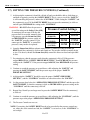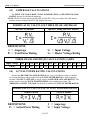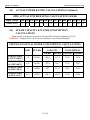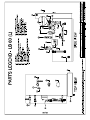
1
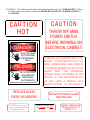
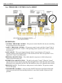
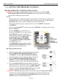
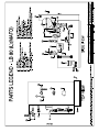
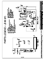
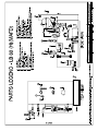
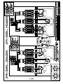
User Manual & Installation Instructions LB-80 IMPORTANT – READ ALL INSTRUCTIONS BEFORE OPERATING All steam boilers are built in accordance with ASME miniature boiler code. NOTE: It is the responsibility of the installer to conform to any state or local codes. If further inspection, following modification by installer, is required under state or local codes, that is the responsibility of the local installer. www.electrosteam.com rev. 12082010 WARNING - The following labels have been placed on this boiler for YOUR SAFETY. Failure to observe these instructions could lead to PROPERTY DAMAGE, SEVERE INJURY, or even DEATH CAU T ION HO T DANGER HIGH VOLTAGE AUTHORIZED PERSONNEL ONLY PELIGRO ALTO VOLTAJE SOLAMENTE PERSONAL AUTORIZADO REPLACE GLASS EVERY SIX MONTHS CAUTION USE ELECTRICAL SUPPLY CONDUCTORS RATED FOR A MINIMUM OF 90°C CA U T I O N THROW OFF MAIN POWER SWITCH BEFORE WORKING ON ELECTRICAL CABINET A MANUAL WAS SHIPPED WITH THIS BOILER. IT IS IMPORTANT THAT YOU READ, UNDERSTAND, AND OPERATE THIS STEAM GENERATOR IN ACCORDANCE WITH THE OPERATING INSTRUCTIONS CONTAINED IN THE MANUAL. IF FOR ANY REASON YOU DO NOT HAVE A MANUAL, CALL ELECRTO-STEAM AT 800-634-8177 RETIGHTEN SIGHT GLASS BEFORE USE TERMINALS ARE SUITABLE FOR COPPER WIRE ONLY U.L. 834 PAR. 4416 AMBIENT TEMPERATURE AROUND UNIT NOT TO EXCEED 105° F LB-80 - User Manual Electro-Steam Generator Corp. TABLE OF CONTENTS 1.) INSTALLATION INSTRUCTIONS .................................................................... 4 2.) OPERATION & SEQUENCE OF EVENTS ..................................................... 5 3.) CLEANING & MAINTENANCE .................................................................... 6-14 MANUAL “BLOW DOWN” ..................................................................................... 6 CLEANING WATER LEVEL PROBES ............................................................... 6-7 CLEANING OR REPLACING HEATERS ............................................................... 7 REPLACING GLASS GAUGE AND RUBBER WASHERS ............................... 8-9 3.4.1) BRASS SIGHT GLASS (STANDARD) ................................................................... 8 3.4.1) BRASS SIGHT GLASS (SEISMIC) ........................................................................ 9 3.5) CHAMBER CLEANING & CHEMICAL TREATMENT ................................ 10-11 3.6) PRESSURE CONTROL DATA SHEET ................................................................. 12 3.7) SETTING THE PRESSURE CONTROLS ....................................................... 13-14 CALCULATIONS & DATA SHEETS ........................................................ 15-17 4.1) HEATER POWER & VOLTAGE RATINGS ......................................................... 15 4.2) TOTAL POWER RATING CALCULATIONS ...................................................... 15 4.3) AMPERAGE CALCULATIONS ............................................................................ 16 4.4) ACTUAL POWER RATING CALCULATIONS ................................................... 16 4.5) STEAM CAPACITY & WATER CONSUMPTION CALCULATIONS ............... 17 DRAWINGS & WIRING SCHEMATICS ................................................. 18-31 5.1) PARTS LEGENDS ............................................................................................ 18-21 5.1.1) LB (80KW) (LOW PRESSURE) (0-15PSI) ............................................................ 18 5.1.2) LB (80KW) (LOW PRESSURE)(MAFD) (0-15PSI) ................................................ 19 5.1.3) LB (80KW) (HIGH PRESSURE)(0-30, 0-100PSI) ................................................... 20 5.1.4) LB (80KW) (HIGH PRESSURE)(MAFD) (0-30, 0-100PSI) ...................................... 21 5.2) INSTALLATION DATA SHEETS .................................................................. 22-25 5.2.1) LB (80KW) (LOW PRESSURE) (0-15PSI) ............................................................ 22 5.2.2) LB (80KW) (LOW PRESSURE)(MAFD) (0-15PSI) ................................................ 23 5.2.3) LB (80KW) (HIGH PRESSURE)(0-30, 0-100PSI) ................................................... 24 5.2.4) LB (80KW) (HIGH PRESSURE)(MAFD) (0-30, 0-100PSI) ...................................... 25 5.3) CONTROL WIRING SCHEMATICS .............................................................. 26-29 5.3.1) LB (LOW PRESSURE) (0-15PSI) ........................................................................ 26 5.3.2) LB (LOW PRESSURE)(MAFD) (0-15PSI) ............................................................ 27 5.3.3) LB (HIGH PRESSURE)(0-30, 0-100PSI) .............................................................. 28 5.3.4) LB (HIGH PRESSURE)(MAFD) (0-30, 0-100PSI) .................................................. 29 5.4) HEATER WIRING SCHEMATICS .................................................................. 30-31 5.4.1) LB (40-80KW) (THREE PHASE) (208-240V) ....................................................... 30 5.4.2) LB (80KW) (THREE PHASE) (380-600V) ............................................................ 31 TERMS & CONDITIONS ..................................................................................... 32 3.1) 3.2) 3.3) 3.4) 4.) 5.) 6.) 3 of 32 LB-80 - User Manual Electro-Steam Generator Corp. 1.) INSTALLATION INSTRUCTIONS LITTLE BOILER “LB-SERIES” The Electro-Steam Generator design consists essentially of a high pressure chamber filled with water that is heated by one or more submerged resistance type electric heating elements. Automatic controls are provided to maintain the pre-set operating pressure and water level. Safety features include: automatic low-water cutoff (manual low-water reset optional), dual pressure controls, safety valve, and visible water level gauge. All of our generators are built in accordance with A.S.M.E. Miniature Boiler Code and are individually inspected and stamped by an Authorized National Board Insurance Inspector. IMPORTANT – READ ALL INSTRUCTIONS BEFORE OPERATING Important – Set unit perfectly level, and as close as possible to the steam vessel or appliance it will operate. For generator measurements, refer to Installation Data Drawing attached. For interpretation of numbered items, refer to Parts Legend Drawing attached. NOTE: Ambient temperature around this unit must not exceed 105°F. CONNECTIONS: Periodically check all plumbing and electrical connections for tightness; this should also be done before initial start-up. ELECTRICAL: This generator must be connected to a disconnect switch protected by fuses or circuit breakers with the proper size wire by a licensed electrician in accordance with N.E.C. and your local codes – Voltage, KW, and Phase requirement are marked on the nameplate. WATER SUPPLY: Connect city water line to Y-Strainer (#6). Purity: NOT to exceed 26,000 OHMS per CM Temperature Range: 32°F – 140°F or 0°C – 60°C. Pressure Range: 20PSI – 150PSI. *CAUTION: The Pump (#8) requires clean tap water. If the water is not free of foreign matter, a 5 micron cartridge filter should be installed in the water supply line. STEAM OUTLET: Connect Steam Outlet Valve (#16) to piece of equipment, vessel, room, or area to be operated by the Electro Steam Generator. SAFETY VALVE & DRAIN: Separately route the Safety Valve (#18) & Drain (#23) to a high temperature drain *NO PVC. Discharging pipe of the Safety Valve (#18) should never be smaller than the valve outlet and should be rigidly supported, placing no weight on the safety valve itself. If equipped with Motorized Auto-Flush & Drain “MAFD” (#20), it should be routed with the Drain (#23). 4 of 32 LB-80 - User Manual Electro-Steam Generator Corp. 2.) OPERATION & SEQUENCE OF EVENTS IMPORTANT – READ INSTALLATION INSTRUCTIONS BEFORE OPERATING 1. Turn on water supply from the source to the Generator. 2. OPEN all valves on the Generator except for the Manual Drain (#19). 3. Place main disconnect switch in ON position. 4. Place ON/OFF Switch (#2) in ON position. 5. x The Water Solenoid (#7) [and Pump (#8), if high pressure] will engage and the chamber will begin to fill with water. As the water level rises, it will make contact with the (G OR D) and (A) probes, indicating the heaters are safely submerged. At this time the contactor(s) will engage, supplying power to the heaters, causing steam pressure to accumulate. x The chamber will continue to fill with water until 1 second after the water makes contact with the (C) probe, causing the Water Solenoid (#7) [and Pump (#8), if high pressure] to turn off. x If the contactor(s) still have not engaged at this time, you may need to press the Safety Reset (#13) on the “Safety” Pressure Control (#12). If your generator is equipped with a Manual Low-Water Reset (MLWR) (#3), it must be pressed at this time to engage the contactor(s). If your generator is equipped with a Motorized Auto-Flush & Drain (MAFD) (#20), you must wait until it closes before the contactor(s) will engage. (approximately 3 minutes) x Steam pressure will continue to rise until is reaches its set operating pressure. This may take up to 25 minutes. At this time, the “Control” Pressure Control (#12) will cause the contactor(s) to disengage. The pressure will drop approximately 2-8 PSI until the “Control” Pressure Control (#12) causes the contactor(s) to reengage, causing the pressure to rise again. The contactor(s) will continue to cycle on and off during operation. The Generator is now fully operational and will produce steam until it is turned off. x 6. As steam is exhausted, the water level will drop until 3 seconds after it breaks contact with the (C) probe. At this time, the Water Solenoid (#7) [and Pump (#8), if high pressure] will engage and the chamber will again fill with water. The chamber will continue filling until 1 second after the water makes contact with the (C) probe. The Water Solenoid (#7) [and Pump (#8), if high pressure] will continue to cycle on and off during operation. To shut off the Generator, place ON/OFF Switch (#2) in OFF position. Pressure will drop naturally as the chamber cools, or the Generator may be drained manually through Manual Drain (#19). (See Manual Blow Down 3.1) WARNING – HOT WATER and STEAM under HIGH PRESSURE can lift drain pipes right off the ground and cause SERIOUS INJURY. Make sure drain pipe is SECURE and CANNOT move. The drain must be directed into a HIGH TEMPERATURE drain (NO PVC) or outside. 5 of 32 LB-80 - User Manual Electro-Steam Generator Corp. 3.) CLEANING & MAINTENANCE The following cleaning procedures are HIGHLY RECOMMENDED in order to keep your Steam Generator in the best operating condition at all times. 3.1) MANUAL “BLOW DOWN” A Manual “Blow Down” is an easy way to GREATLY extend the life of your Steam Generator. Using a Motorized Auto-Flush & Drain (MAFD) of course helps, but is not a “Cure all”. The following is the LEAST amount of times recommended to blow down your generator: NORMAL WATER AREAS – Should be done ONCE A WEEK. BAD WATER AREAS – Should be done ONCE A DAY. NORMAL WATER AREAS WITH MAFD – Should be done TWICE A MONTH. BAD WATER AREAS WITH MAFD – Should be done ONCE A WEEK. NOTE: The best time to Blow Down your generator is after it has been running for some time, while it is still hot. 1. Place Toggle Switch (#2) and Main Disconnect Box in OFF position. 2. Allow pressure to drop between 10 and 20 PSI. 3. Open Manual Drain (#19) slowly, allowing HOT WATER and STEAM to blow out into the drain, cleaning out the generator. NOTE: Blow Down your generator at any pressure you feel comfortable with. 10 to 20 PSI is only a recommendation. You may go higher or lower, but higher is always better. WARNING – HOT WATER and STEAM under HIGH PRESSURE can lift drain pipes right off the ground and cause SERIOUS INJURY. Make sure drain pipe is SECURE and CANNOT move. The drain must be directed into a HIGH TEMPERATURE drain (NO PVC). 3.2) CLEANING WATER LEVEL PROBES Water Level Probes are the heart of your generator. Almost all steam generator malfunctions are caused by dirty water level probes. CLEANING your PROBES is by far the MOST IMPORTANT maintenance step to keep your generator running properly. The following is the LEAST amount of times recommended to clean your probes: NORMAL WATER AREAS – Should be done TWICE A YEAR. BAD WATER AREAS – Should be done 3-4 TIMES A YEAR. NOTE: The best time to clean your probes is before you turn your generator on, while it is still cool. 1. Place Toggle Switch (#2) and Main Disconnect Box in OFF position. 2. Make sure generator is cool and the Pressure Gauge (#15) reads 0 PSI. 3. Locate the blue box on top of generator and remove cover plate, exposing the Water Level Probes (#5). 4. Use 5/16” Socket to remove wires from probes. 5. Use 13/16” Spark Plug Socket to remove probes from chamber. 6 of 32 LB-80 - User Manual Electro-Steam Generator Corp. 3.2) CLEANING WATER LEVEL PROBES (Continued) 6. 7. 8. 9. Clean probes to remove rust and scaling. NOTE: To clean probes you may use wire wheel, wire brush, steal wool, or Scotch-Brite. (Wire wheel works the best) You may also want to try some sort of chemical like CLR remover or LIME-A-WAY. Reinstall probes assuring each probe’s length is assigned to its proper letter. Reconnect wires to probes assuring each color is also assigned to its proper letter. NOTE: DO NOT make wires too tight. Just tighten enough to make contact. Over tightening can cause probe plugs to pull apart over time. Reinstall cover plate. Water Level Probe Specifications: Letter Assignment on Chamber Water Level Probe Length Wire Color Assignment Assignment on Dual Function Board A 5 ¼” RED LLCO B C D/G Not Used 3 ¾” 5 ½” Not Used BLACK GREEN Not Used H G NOTE: The (B) Probe is not used. WARNING – There MUST be NO PRESSURE in the chamber when removing probes. If you must change probes while chamber is HOT, make sure the steam out and drain valves are open to assure chamber will remain depressurized. DO NOT touch probes with your bare hands while HOT, and be cautious of escaping steam from probe holes while probes are removed. 3.3) CLEANING OR REPLACING HEATERS Heaters are located inside the control panel (#1) below the insulation barrier, bolted into the chamber. If (3.5) Chamber Chemical/Acid Treatments are not regularly done, heaters must be taken out at least ONCE A YEAR, cleaned with wire brush and reinstalled using a new gasket. If you are replacing or cleaning your heater elements: 1. Place Toggle Switch (#2) and Main Disconnect Box in OFF position. 2. Make sure generator is cool and the Pressure Gauge (#15) reads 0 PSI. 3. Remove heater wires from heater(s), using a 3/8” Socket. 4. Unbolt and remove heater(s) using a 1 1/16” Socket. NOTE: Heater(s) may be difficult to get out; you may need to use some sort of pry bar to get them loose. 5. Clean heater(s) with wire brush. If replacing, dispose of old heater(s). 6. Reinstall heater(s) with new gasket(s). 7. Attach heater wires assuring proper wiring. *Refer to Heater Wiring Schematics attached* NOTE: If you are replacing a heater because of a heater failure, you must also clean the probes and clean out the chamber, or you may have another heater failure within 48 hours. 7 of 32 LB-80 - User Manual Electro-Steam Generator Corp. 3.4) REPLACING GLASS GAUGE & RUBBER WASHERS OR GLASS PACKINGS The Sight Glass (#10) gives the operator the ability to easily monitor the actual water level inside the chamber. If the Sight Glass (#10) gets clogged or is no longer functional, it can be very difficult to troubleshoot a problem. 3.4.1) BRASS SIGHT GLASS (STANDARD) GLASS GAUGE and RUBBER WASHERS MUST be replaced EVERY SIX MONTHS INSTALLATION: Only properly trained personnel should install and maintain water gauge glass and connections. Remember to wear safety gloves and glasses during installation. Before installing, make sure all parts are free of chips and debris. 1. Uninstall GUARD RODS, GLASS GAUGE, and RUBBER WASHERS. (You may need to rotate one of the GAUGE FITTINGS to remove GLASS GAUGE) 2. Slip a new RUBBER WASHER on the new GLASS GAUGE about an inch from the bottom. 3. Now slip the following items through the top of GLASS GAUGE in the following order: • FRICTION WASHER • GLASS PACKING NUT (facing down) • GLASS PACKING NUT (facing up) • FRICTION WASHER • RUBBER WASHER (inch down from top) 4. Gently insert GLASS GAUGE into GAUGE FITTINGS. You may need to rotate GAUGE FITTINGS until vertically aligned, after GLASS GAUGE is in. 5. Carefully raise GLASS GAUGE about 1/16” from bottom and slide lower RUBBER WASHER down until it makes contact with the BOTTOM GAUGE FITTING. (DO NOT allow GLASS GAUGE to remain in contact with any metal) 6. Carefully slide upper RUBBER WASHER up as far as possible. 7. Hand tighten both GLASS PACKING NUTS, then tighten 1/2 turn more by wrench. Tighten only enough to prevent leakage. DO NOT OVER TIGHTEN! If any leakage should occur, tighten slightly, a quarter turn at a time, checking for leakage after each turn. 8. Reinstall GUARD RODS. 8 of 32 LB-80 - User Manual Electro-Steam Generator Corp. 3.4) REPLACING GLASS GAUGE & RUBBER WASHERS OR GLASS PACKINGS (Continued) The Sight Glass (#10) gives the operator the ability to easily monitor the actual water level inside the chamber. If the Sight Glass (#10) gets clogged or is no longer functional, it can be very difficult to troubleshoot a problem. 3.4.2) BRASS SIGHT GLASS (SEISMIC) GLASS GAUGE and GLASS PACKINGS MUST be replaced EVERY SIX MONTHS The Seismic Sight Glass is equipped with BALL CHECKS in each GAUGE FITTING. INSTALLATION: Only properly trained personnel should install and maintain water gauge glass and connections. Remember to wear safety gloves and glasses during installation. Before installing, make sure all parts are free of chips and debris. 1. Uninstall GUARD RODS, GLASS GAUGE, and GLASS PACKINGS. (You may need to rotate one of the GAUGE FITTINGS to remove GLASS GAUGE) 2. Slip a new GLASS PACKINGS on the new GLASS GAUGE about an inch from the bottom. 3. Now slip the following items through the top of GLASS GAUGE in the following order: • PACKING GLAND (facing down) • GLASS PACKING NUT (facing down) • GLASS PACKING NUT (facing up) • PACKING GLAND (facing up) • GLASS PACKINGS (inch down from top) • PACKING WASHER 4. Gently insert GLASS GAUGE into GAUGE FITTINGS. You may need to rotate GAUGE FITTINGS until vertically aligned, after GLASS GAUGE is in. 5. Carefully raise GLASS GAUGE about 1/16” from bottom and slide lower GLASS PACKINGS down until it makes contact with the BOTTOM GAUGE FITTING. (DO NOT allow GLASS GAUGE to remain in contact with any metal) 6. Carefully slide upper GLASS PACKINGS up as far as possible. 7. Hand tighten both GLASS PACKING NUTS, then tighten 1/2 turn more by wrench. Tighten only enough to prevent leakage. DO NOT OVER TIGHTEN! If any leakage should occur, tighten slightly, a quarter turn at a time, checking for leakage after each turn. 8. Reinstall GUARD RODS. 9 of 32 LB-80 - User Manual Electro-Steam Generator Corp. 3.5) CHAMBER CHEMICAL/ACID TREATMENT All Electric Steam Generator should be cleaned regularly. The following is the least amount of times recommended to clean out your chamber: NORMAL WATER AREAS – Should be done ONCE A YEAR. BAD WATER AREAS – Should be done TWICE A YEAR. If equipped with Motorized Auto-Flush & Drain “MAFD” (#20), locate the MAFD TIMER/RELAY in the Control Panel (#1) and do steps 1-3 before the chamber treatment and steps 4-5 after chamber treatment is done: WARNING – Before opening Control Panel (#1), TO AVOID ELECTRICAL SHOCK, place Main Disconnect Box and the Toggle Switch (#2) in the OFF position. BEFORE: 1. Dial TIME ADJUSTMENT on MAFD TIMER/RELAY all the way down to 15 seconds. 2. Make sure MAFD (#20) in the closed position. 3. Disconnect the orange wire from the normally open (NO) terminal on the MAFD TIMER/RELAY. AFTER: 4. Reconnect the orange wire to the normally open (NO) terminal on the MAFD TIMER/RELAY. 5. Dial TIME ADJUSTMENT on MAFD TIMER/RELAY up to the desired flush time (Most commonly 3 minutes) Chamber Treatment Instructions: 1. Turn on generator, allowing pressure to climb to 10 to 20 PSI on Pressure Gauge (#15), and then shut off. 2. “Blow Down” Open Manual Drain (#19) slowly, allowing HOT WATER and STEAM to blow out into the drain. NOTE: You may Blow Down your generator at any pressure you feel comfortable with. 10 to 20 PSI is only a recommendation. You may go higher or lower, but higher is always better. WARNING – HOT WATER and STEAM under HIGH PRESSURE can lift drain pipes right off the ground and cause SERIOUS INJURY. Make sure drain pipe is SECURE and CANNOT move. The drain must be directed into a HIGH TEMPERATURE drain (NO PVC). 3. Remove Safety Valve (#18). WARNING – There MUST be NO PRESSURE in the chamber when removing the Safety Valve (#18), make sure the steam out and drain are open to assure chamber will remain depressurized. Be cautious of escaping steam from chamber while Safety Valve (#18) is removed. 10 of 32 LB-80 - User Manual Electro-Steam Generator Corp. 3.5) CHAMBER CHEMICAL/ACID TREATMENT (Continued) 4. Close Manual Drain (#19) and Steam Out (#16); turn generator on until Sight Glass (#10) shows that it is 1/2 full, and then shut off. 5. Insert funnel into coupling, where Safety Valve (#18) used to be. 6. Pour 1 Gallon of hydrochloric acid (inhibited) solution (NON-FOOD APPLICATIONS) into funnel very slowly, being careful of fumes and venting while pouring. NOTE: Solution can be obtained from any industrial chemical dealer. FOR FOOD APPLICATIONS: Use FDA approved chemicals. 7. Remove funnel, reinstall Safety Valve (#18), and verify Steam Out (#16) is closed; let solution set in generator for 1 HOUR. 8. Turn on generator, allowing pressure to climb to 5 PSI on Pressure Gauge (#15), and then shut off. 9. Allow the pressure to drop to 0 PSI on Pressure Gauge (#15) naturally. DO NOT open Steam Out (#16) or Manual Drain (#19) until pressure is down. 10. Remove Safety Valve (#18). 11. Reinsert funnel, and fill generator completely to the top with clean water; let stand for an additional 1/2 HOUR. NOTE: Turning on the generator will not completely fill it to the top. Filling must be done manually through the safety valve coupling. 12. Open Manual Drain (#19) to drain generator. 13. Close Manual Drain (#19); refill generator completely to the top with clean water and open Manual Drain (#19) to flush out generator completely. 14. Reinstall Safety Valve (#18) and close Manual Drain (#19). 15. Turn on generator, allowing pressure to climb to 10 to 20 PSI on Pressure Gauge (#15), and then shut off. 16. “Blow Down” Open Manual Drain (#19) slowly, allowing HOT WATER and STEAM to blow out into the drain. NOTE: You may Blow Down your generator at any pressure you feel comfortable with. 10 to 20 PSI is only a recommendation. You may go higher or lower, but higher is always better. WARNING – HOT WATER and STEAM under HIGH PRESSURE can lift drain pipes right off the ground and cause SERIOUS INJURY. Make sure drain pipe is SECURE and CANNOT move. The drain must be directed into a HIGH TEMPERATURE drain (NO PVC). 17. Your generator is now ready for normal use and operation. 11 of 32 LB-80 - User Manual Electro-Steam Generator Corp. 3.6) PRESSURE CONTROL DATA SHEET DEFINITIONS: “CONTROL” PRESSURE CONTROL – This pressure control should be the only one controlling the operating pressure of the generator. “SAFETY” PRESSURE CONTROL – This pressure control is only used if the “Control” fails. It is always set higher than the “Control”; if the operating pressure is passed, The “Safety” will turn the heaters off. SAFETY RESET – This reset is tripped when the “Safety” turns the heaters off. It must be manually pushed to turn the heaters back on. This lets the user know there was a problem. If it is tripped, the “Control” most likely failed. PRESSURE ADJUSTING DIAL – These dials adjust the set pressure at which each pressure control will turn the heaters off. DIFFERENTIAL ADJUSTING DIAL – This dial is only on the “Control”. When the “Control” turns the heaters off, the amount of pressure that is dropped before it turns the heaters back on (the differential) can be adjusted by this dial. This dial should never have to be adjusted, unless desired. PRESSURE GAUGE – This tells the user what pressure is in the chamber. The pressure controls are set to this gauge. 5 PSI PRESSURE CONTROL – (Only used with “MAFD” Motorized Auto-Flush & Drain) this control prevents the MAFD from opening when there is more than 5 pounds off pressure in the generator. 12 of 32 LB-80 - User Manual Electro-Steam Generator Corp. 3.7) SETTING THE PRESSURE CONTROLS SETTING PRESSURE CONTROLS INSTUCTIONS: WARNING – The pressure controls must be set while all circuits are live. TO AVOID ELECTRICAL SHOCK, DO NOT TOUCH the wires or the terminals in which they connect while setting the pressure controls. NOTES: - Setting the pressure controls greatly relies on your ability to tell whether the contactor(s) are turning the heaters on or off. You should be able to hear the contactor(s), located inside the Control Box (#1), click on and off. Familiarize yourself with this sound. - The order in which the pressure controls must be set is the “SAFETY” and then the “CONTROL”. - In order to set the “SAFETY” you must keep the “CONTROL” at a higher pressure setting than the “SAFETY” - Once the “SAFETY” is set, then you can lower the “CONTROL” to its correct setting. - To INCREASE the pressure setting, when looking down on pressure control, using your two index fingers, turn the PRESSURE ADJUSTMENT DIAL CLOCKWISE, causing the BLACK INDICATOR LINE to move DOWN the scale. - To DECREASE the pressure setting, turn the dial COUNTER CLOCKWISE, causing the indicator line to move UP the scale. SETTING INSTRUCTIONS: 1. Open the pressure control covers, as shown on previous page. 2. Adjust the PRESSURE ADJUSTMENT DIAL on the “CONTROL” so that the BLACK INDICATOR LINE is somewhere between ½ and ¾ of the way down from the top. 3. Adjust the PRESSURE ADJUSTMENT DIAL on the “SAFETY” so that the BLACK INDICATOR LINE is somewhere between ¼ and ½ of the way down from the top. 4. Close the Steam Out (#16) and turn on generator. When the contactor(s) click on, the pressure will rise. If contactor(s) do not click on right away, you may need to press SAFETY RESET. Continue to watch the Pressure Gauge (#15) until you hear the contactor(s) click off. This may take up to 20 minutes. WARNING – DO NOT allow the pressure to exceed the rating on the Safety Valve (#18). If contactor(s) do not turn off before the pressure limit is exceeded, manually shut off generator, open the Steam Out (#16), and DECREASE the pressure setting on the “SAFETY” pressure control. Repeat step #4. 13 of 32 LB-80 - User Manual Electro-Steam Generator Corp. 3.7) SETTING THE PRESSURE CONTROLS (Continued) 5. At this point the contactor(s) should be clicked off and you should be able to click them on and then off again by pressing the SAFETY RESET. This is a way to test if the “SAFETY” is still controlling the pressure, and not the “CONTROL”. While setting the “SAFETY” and the contactor(s) are off, if the SAFETY RESET does not cause the contactor(s) to click on and off again, INCREASE the setting on the “CONTROL” WARNING – DO NOT allow the pressure to exceed the rating on the Safety Valve (#18). If contactor(s) do not turn off before the pressure limit is exceeded, manually shut off generator, open the Steam Out (#16), and DECREASE the pressure setting on the “SAFETY” pressure control. If you cannot get the “SAFETY” to control the pressure, it may need to be replaced. Pressure Control Settings High Pressure (0-100 PSI) High Pressure (0-30 PSI) Low Pressure (0-15 PSI) “Control” “Safety” 80 PSI 85 PSI 25 PSI 27 PSI 11 PSI 13.5 PSI 6. Open the Steam Out (#16) to exhaust some pressure. Continue pressing the SAFETY RESET until the contactor(s) click on and remain on. The pressure should eventually begin to rise. If it doesn’t, throttle the Steam Out (#16) somewhere between closed and open until it does. 7. Pay attention to what the pressure reads when the contactor(s) click off. If the pressure stopped BELOW the “SAFETY PRESSURE SETTING”, then INCREASE the pressure setting on the “SAFETY”. If the pressure stopped ABOVE, then DECREASE the pressure setting. 8. Continue to watch the pressure go up and down, while adjusting the “SAFETY” and pressing the SAFETY RESET, until the pressure stops at the proper “SAFETY PRESSURE SETTING”. 9. At this point the “SAFETY” should be set to the proper “SAFETY PRESSURE SETTING”, and the “CONTROL” should be set somewhere above the “SAFETY”. 10. Let the pressure drop below the “OPERATING PRESSURE SETTING” and then press the SAFETY RESET, so that the contactor(s) click on. DECREASE the pressure setting on the “CONTROL” until the contactor(s) click off. 11. Repeat Step 10 until you no longer need to press the SAFETY RESET for the contactor(s) to click on. 12. Continue to watch the pressure go up and down, while adjusting the “CONTROL”, until the pressure stops at the proper “OPERATING PRESSURE SETTING”. 13. The Pressure Controls are now set. NOTE: If at anytime the SAFETY RESET needs to be pressed after the pressure controls are set, either one of the controls are bad, the “SAFETY” is set too low, or the “CONTROL” is set too high. 14 of 32 LB-80 - User Manual Electro-Steam Generator Corp. 4.) CALCULATIONS AND DATA SHEETS 4.1) HEATER POWER & VOLTAGE RATINGS LB 80 Model units use (3) 25KW heaters to meet the required 75KW of POWER from the customer’s specified INPUT VOLTAGE. Each heater comes 4 different VOLTAGE RATINGS. AVAILABLE HEATER RATINGS KW 25 POWER RATINGS per MODEL VOLTAGES 208 230 480 600 MODEL UNIT QUAN. KW LB-80 3 25 HEATER VOLTAGE RATINGS per INPUT VOLTAGE (VOLTS) Input Voltage 208 220 230 240 380 400 415 425 440 460 480 550 575 600 LB-80 208 230 230 230 208 230 230 230 480 480 480 600 600 NOTE: 380-425V heaters are not usually rated for 380-425V. They are usually 208-240V heaters that have been re-stamped 380-425V and jumpered in series. 4.2) TOTAL POWER RATING CALCULATIONS The HEATER POWER RATING and NUMBER OF HEATERS are used to calculate the TOTAL POWER RATING. Since the HEATER POWER RATINGS are in Kilowatts, they must be multiplied by 1000 to convert them to Watts. MODEL UNIT LB-80 Heater Power Rating (Watts) X Number of Heaters Total Power Rating (Watts) 25,000 DEFINITIONS: PT = Total Power Rating PH = Heater Power Rating xH = X Number of Heaters 15 of 32 3 75,000 600 LB-80 - User Manual 4.3) Electro-Steam Generator Corp. AMPERAGE CALCULATIONS The INPUT VOLTAGE, PHASE, TOTAL POWER RATING, and HEATER VOLTAGE RATING are used to calculate the amperage. NOTE: 380-425V heaters are not usually rated for 380-425V. They are usually 208-240V heaters that have been re-stamped 380-425V and jumpered in series. FORMULAS TO CALCULATE THREE PHASE AMPERAGE 208-240V & 440-600V 380-425V (using 208-240V heaters) DEFINITIONS: I = Amperage PT = Total Power Rating VI = Input Voltage VH = Heater Voltage Rating THREE PHASE AMP DRAW CALCULATIONS (AMPS) Input Voltage LB-80 4.4) 208 220 230 240 380 400 415 425 440 460 480 550 575 600 208 180 188 196 127 109 113 116 82.7 86.5 90.2 66.2 69.2 72.2 ACTUAL POWER RATING CALCULATIONS Because the HEATER VOLTAGE RATINGS only come in 4 different voltages, and there are so many different voltages in the field, the TOTAL POWER RATING is only completely accurate if the INPUT VOLTAGE is exactly equal to the HEATER VOLTAGE RATING. This means, in most cases, the TOTAL POWER RATING is not completely accurate. The AMERAGE and INPUT VOLTAGE can be used to calculate the ACTUAL POWER RATING. FORMULAS TO CALCULATE ACTUAL POWER RATINGS THREE PHASE DEFINITIONS: PA = Actual Power Rating SINGLE PHASE I = Amperage VI = Input Voltage 16 of 32 LB-80 - User Manual 4.4) Electro-Steam Generator Corp. ACTUAL POWER RATING CALCULATIONS (Continued) (3PH) ACTUAL POWER RATING CALCULATIONS (LB-80) Input Voltage Power (KW) 4.5) 208 220 230 240 380 400 415 425 440 460 480 550 575 600 75 68.6 75 81.7 83.4 75.6 81.4 85.4 63 68.9 75 63 68.9 STEAM CAPACITY & WATER CONSUMPTION CALCULATIONS Steam Capacity Calculations are based on the impossible feed water temperature of 212°F. WARNING – Anything above 140°F will cause damage to water solenoid and pump. STEAM CAPACITY & WATER CONSUMPTION CALCULATIONS FEED WATER @ 212°F (100°C) FEED WATER @ 140°F (60°C) FEED WATER @ 100°F (38°C) FEED WATER @ 60°F (16°C) AVERAGE STEAM CAPACITY LB/HR KG/HR AVERAGE WATER CONSUMPTION GAL/HR LIT/HR BHP BTU/HR 7.5 251063 258.8 117.4 31.01 117.4 6.75 225956 232.9 105.7 27.91 105.7 6 200850 207 93.91 24.81 93.91 5.63 188297 194.1 88.04 23.26 88.04 17 of 32 75 ELECTRO-‐STEAM GENERATOR CORPORATION TERMS AND CONDITIONS OF SALE EXCLUSIVE AND ENTIRE: The following Standard Terms and Conditions are intended by the parties to govern all the purchases of equipment, parts or service from Seller, and together with the specifications provided or embodied herewith, represent the entire understanding of the parties without exception. All other terms and conditions are specifically rejected, and by proceeding with the transaction in any manner, both Seller and Buyer agree that these Standard Terms and Conditions shall control. The price charged by Seller is based on these Standard Terms and Conditions. DOMESTIC TERMS TERMS: Net 30 days. A "late payment" in the form of interest at the rate of 2% per month or a service charge of like amount will be levied on all late payments (the type of charge being consistent with the applicable local law). Invoices will be submitted when the equipment, part, service is supplied. Attention to these terms will eliminate delays in starting up any equipment or providing further service or parts. NOTE: Terms pending credit approval. INTERNATIONAL TERMS TERMS: Advanced payment (wire transfer, credit card, or cash in advance) or confirmed letter of credit. TAXES: No taxes of any kind are included. All prices herein and/or contracts shall be subject to increase without notice by the amount of present or future sales or excise tax levied or charged, either by Federal, State or any other assessing agency. CHANGES: Changes made after fabrication has begun shall be submitted in writing, signed by Buyer. Buyer agrees to pay the cost of any changes. The specifications and prices are subject to change without notice. CLAIMS: Title passes to the Buyer upon delivery to the carrier, unless otherwise indicated. Safe delivery is the responsibility of the carrier. Damaged merchandise, if accepted, should be noted on the delivery receipt and on the freight bill before acceptance of shipment. Make claim promptly. LOCAL CODES: All steam boilers are built in accordance with ASME miniature boiler codes. NOTE: It is the responsibility of the installer to conform to any state or local codes. If further inspection following modifications by the installer is required under state and local codes it is the responsibility of the local installer. SEVERABLE AND INDEPENDENT PROVISION: WITHOUT LIMITING THE FOREGOING, IT IS EXPRESSLY UNDERSTOOD AND AGREED THAT EACH AND EVERY PROVISION OF THIS AGREEMENT THAT PROVIDES FOR A LIMITATION OF LIABILITY, DISCLAIMER OF WARRANTIES, OR EXCLUSION OF DAMAGES IS INTENDED BY THE PARTIES TO BE SEVERABLE AND INDEPENDENT OF ANY OTHER PROVISION AND TO BE ENFORCED AS SUCH, FURTHER, IT IS EXPRESSLY UNDERSTOOD AND AGREED THAT IN THE EVENT ANY REMEDY HEREUNDER IS DETERMINED TO HAVE FAILED ITS ESSENTIAL PURPOSE, ALL OTHER LIMITATIONS OF LIABILITY AND EXCLUSION OF DAMAGES SET FORTH HEREIN SHALL REMAIN IN FULL FORCE AND EFFECT. ALL SUCH PROVISIONS SHALL SURVIVE THE TERMINATION OF THIS AGREEMENT. NO ACTION, REGARDLESS OF FORM, ARISING OUT OF THE TRANSACTIONS OF THIS AGREEMENT MAY BE BROUGHT BY BUYERMORE THAN ONE YEAR AFTER THE CAUSE OF ACTION HAS ACCRUED. WARRANTY: Seller warrants that the equipment, service, software, repair or parts supplied shall conform to the description. In the event that any part or parts, excepting expendable items such as, but not limited to, coil liners, thermocouples, refractories and other similar consumable items, that fail due to defects in material or workmanship within the first twelve (12) months of startup of equipment or eighteen (18) months after shipment, whichever occurs first, or in the case of service, repairs, or parts, within twelve (12) months of supplying such service, repair or part, Seller shall at its option, repair or replace EXW (Ex works), such defective part or parts. If the equipment, service, repair or part included software, Seller warrants, for a period of twelve (12) months of startup or eighteen (18) months after shipment, whichever occurs first, that the software supplied or serviced will meet its published functional specifications. Should software fail to meet the specifications, or be otherwise defective, Seller shall promptly correct errors or non-‐conformities. If correction is not possible, Seller shall replace defective software, or, at Seller=s option, refund the purchase price paid for such software. The warranty obligations of Seller with respect to equipment not manufactured by Seller shall conform to and be limited to the warranty actually extended to Seller by its suppliers. Notice of a claim for alleged defective equipment must be given within fifteen (15) days after Buyer learns of the defect. The defective part or parts shall be returned to Seller, freight prepaid, unless otherwise directed by Seller. This warranty shall be exclusive and in lieu of any other warranties and Seller makes no warranty of merchantability or warranties of any other kind express or implied, including any implied warranty of fitness for a particular purpose which extend beyond the warranty as set forth above. Seller=s liability for any and all losses and damages to Buyer resulting from defective parts of equipment shall in no event exceed the cost of repair or replacement, EXW of defective parts or equipment. IN NO EVENT SHALL SELLER BE LIABLE FOR INCIDENTAL, SPECIAL OR CONSEQUENTIAL DAMAGES OF ANY KIND OR NATURE WHATSOEVER. PATENT INDEMNITY: Seller agrees to indemnify Buyer against any proven claim and assessed liability for infringement of any United States patent arising from the manufacture or sale of any apparatus furnished by Seller to Purchaser. THE FOREGOING STATES SELLER'S ENTIRE LIABILITY FOR CLAIMS OR PATENT INFRINGEMENT. Seller shall have no liability whatsoever if the claim of infringement arises out of Seller's compliance with Purchaser's specifications. Seller shall have no liability whatsoever if a claim of infringement is based upon the Purchaser's use of the equipment as part of a patented combination where the other elements of the combination are not supplied by Seller, or in the practice of a patented process. Where the specifications, process, design are supplied by Purchaser, then Buyer agrees to indemnify Seller in like manner. PROPRIETARY RIGHTS: Unless otherwise stated herein all design, manufacturing processes, manufacturing information, vendor sources, know-‐how, equipment, tooling or other hardware, software, or information (collectively referred to as "resources") acquired or utilized by the Seller to produce the finished goods, and any intellectual property rights, including but not limited to patents, copyrights and trade secrets related in any way to the resources, are and shall hereinafter remain the exclusive property of the Seller, regardless of whether such resources are created solely by the Seller, or by Buyer's collaboration with the Seller, for example, where Seller utilizes Buyer's specifications to create resources, and the Buyer shall acquire or receive no rights or title therein or thereto as a result of this purchase whether or not the order provides for Seller's delivery of technical data, drawings or other information to the Buyer in addition to the finished goods. Unless Seller's prior written consent is given, in no event shall the Buyer permit such data, drawings or information to be: (1) disclosed to any third party other than the Buyer's customer; (2) used by the Buyer or the Buyer's customer for manufacture of like or similar goods; (3) used for purposes of duplicating or reverse-‐engineering Seller's proprietary designs or processes; or (4) used by a party other than the Buyer or the Buyer's customer for any purpose. LIMITATION OF LIABILITY: SELLER'S TOTAL AGGREGATE LIABILITY (ARISING OUT OF OR IN CONNECTION WITH BUT NOT LIMITED TO ANY BREACH OF CONTRACT, NEGLIGENCE, TORT, LIQUIDATED DAMAGES, SPECIFIC PERFORMANCE, TERMINATION, CANCELLATION INCLUDING THE REPAYING OF THE CONTRACT PRICE OR PARTS THEREOF, FUNDAMENTAL BREACH, BREACH OF WARRANTIES, MISREPRESENTATION, NONPERFORMANCE, NONPAYMENT, OR ANY OTHER) WHETHER BASED IN CONTRACT, IN TORT, IN EQUITY, ON STATUE, AT LAW OR ON ANY OTHER THEORY OF LAW, SHALL NOT EXCEED THE PAID CONTRACT PRICE. THE BUYERACKNOWLEDGES THAT THE REMEDIES PROVIDED IN THIS CONTRACT ARE EXCLUSIVE AND IN LIEU OF ALL OTHER REMEDIES AVAILABLE TO THE BUYERAT LAW, IN CONTRACT, IN TORT, IN STATUTE OR IN EQUITY OR IN ANY OTHER THEORY OF LAWS. INSURANCE: Buyer represents that they have a program of Insurance which adequately protects their interest, and that of their employees and agents, including damage to plant, property and equipment, personal injury of any kind, directly or indirectly related in any way to the equipment, service, repair or parts supplied by Seller. Accordingly, Buyer waives any claim against Seller for the foregoing, and on behalf of its Insurance Company, any right of subrogation in connection therewith. U.S. EXPORT CONTROLS: All items furnished by Seller to Buyer in connection herewith shall at all times be subject to the export control laws and regulations of the U.S. including, but not limited to, 10 CFR Part 810 and U.S. Export Administration Regulations. Buyer agrees and give assurance that no items, equipment, materials, service, technical data, technology, software or other technical information or assistance furnished by Seller, or any good or product resulting therefrom, shall be exported or re-‐ exported by Buyer or its authorized transferees, if any, directly or indirectly, unless in accordance with applicable U.S. export laws and regulations. The aforesaid obligations shall survive any satisfaction, expiration, termination or discharge of any other contract obligations. FREIGHT TERMS: F.O.B. Factory. Unloading and transportation to job site are at the Buyers expense. INSTALLATION: No installation or job supervision charges are included. RETURN OF MATERIAL: No goods will be accepted for return without a return authorization number from the factory. A 25% restocking fee is charged on returns, freight prepaid. FORCE MAJEURE: If the performance of any part of this contract by Seller is rendered commercially impracticable by reason of any strike, fire, flood, accident, or any other contingency, the non-‐occurrence of which was a basic assumption of this contract including war, embargo, government regulation, or any unforeseen shutdown of major supply sources or other like causes beyond the control of Seller such as cannot be circumvented by reasonable diligence and without unusual expense, Seller shall be excused from such performance in whole or in part to the extent that it is prevented and for as long a period of time as these conditions render Seller's performance commercially impractical. LAW: This Agreement shall be governed by the internal laws of the State of New Jersey, USA, and any claims arising hereunder shall be prosecuted in the US District Court having jurisdiction of causes arising in the District in which Seller is located. CISG (the Convention for the International Sale of Goods) is expressly rejected.