1
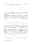
HELIOS™ MANUAL v1.2
manual
helios
™
REAL-TIME VIDEO IMAGE
ENHANCEMENT SYSTEM
TABLE OF CONTENTS
IMPORTANT SAFETY INSTRUCTIONS
1
1.0 INTRODUCTION
2
1.1
About This Manual
2
1.2
What’s Included
2
1.3
System Description
3
2.0 SET-UP
5
2.1
Specifications
5
2.2
Standard Helios™ System Set-up
5
2.2.1
RCA Configuration
6
2.2.2
DB15 Configuration
6
2.3
Embedded Helios™ System Set-up
6
2.3.1
Video Through RCA
7
2.3.2
Video Through Mini Coax
8
2.4
The Helios™ PC Controller Software Set-up
9
2.4.1
Helios™ Controller Software Installation
3.0 OPERATION
10
11
3.1
Keypad Overview
11
3.2
Basic Functions (Normal Mode)
11
3.2.1
Power On/Off
11
3.2.2
Frame Adjustment
12
3.2.3
Setting Adjustment
12
3.2.4
AUTO On/Off
12
3.2.5
Save/Recall Settings
12
3.2.6
Restore Factory Defaults
13
3.3
Advanced Functions (Software Mode)
13
3.3.1
Save/Recall Settings
13
TECHNICAL SUPPORT
14
EC DECLARATION OF CONFORMITY
15
HELIOS™ MANUAL v1.2
IMPORTANT SAFETY INSTRUCTIONS
When using an electrical appliance, basic safety precautions should always be followed,
including the following. Read all instructions before using power supplies.
DANGER — To reduce the risk of electric shock: A power supply should never be left unattended
when plugged in. Always unplug this power supply from the electric outlet immediately after using.
WARNING — To reduce the risk of burns, fire, electric shock, or injury to persons:
1. Do not allow to be used as a toy. Pay close attention when this power supply is used by or near children.
2. Use this power supply only for its intended use as described in this manual. Use only attachments
recommended by the manufacturer as contained in this manual.
3. Never operate this power supply if it has a damaged cord or plug, if it is not working properly, if it
has been dropped or damaged, or fallen into water. In such cases, return the appliance to the nearest
authorized dealer or service center for examination, repair, electrical or mechanical adjustment.
4. Never drop or insert any object into any openings.
5. Do not operate where aerosol (spray) products are being used or where oxygen is being administered.
6. The socket-outlet should be installed near the power supply and should be easily accessible.
7. Do not unplug by pulling on cord. To unplug, pull on the plug, not the cord.
1
INTRODUCTION
1.1
1.0
About This Manual
The purpose of this manual is to provide information only. It is subject to change without
notice and does not represent a commitment on the part of Inuktun Services Ltd., or its agents.
Prior to shipment, the Helios™ was tested and found to comply with factory standards.
If any problems develop with the system, please contact Inuktun Services Ltd.
© 2012 Inuktun Services Limited. All Rights Reserved.
1.2
What’s Included
Please take a moment to ensure that the following items are included with your system.
StandardStandardEmbedded
Helios™Helios™Helios™
System – RCASystem – DB15System
•
•
•
•
•
Helios™ Device – RCA
Helios™ Device – DB15
2 RCA Cables
5VDC Wall Adaptor Mini USB Cable Helios™ Controller Software Install CD Helios™ PCB
in device
in device
Microcontroller PCB
in device
in device
Keypad Membrane
in device
in device
DB15 to DB15 Cable
This Manual •
•
•
•
•
•
•
•
•
•
•
2
1.0 INTRODUCTION
1.3
System Description
High quality video can be difficult to capture due to adverse conditions such as low light, dust, rain,
snow, fog, smoke and turbid water. Helios™, Inuktun’s real-time video image enhancement system,
automatically corrects these visibility issues and substantially improves image clarity, brightness and
edge-emphasis. The Helios™ platform exposes new video image details that escape the naked eye.
Helios™ is a highly affordable hardware / software option that integrates with standard Inuktun
controllers and cameras. This innovative solution from Inuktun is essential to the work flow of
inspection professionals responsible for mission critical video. See it for yourself.
Figure 1-1: Standard Helios™ System – RCA Diagram
Keypad Membrane
5VDC In
Video Out
Video In
Mini USB
• Mini USB — provides power and/or connection to a computer for software control
• Keypad Membrane — control panel for Helios™
• 5VDC In — provides power via 5VDC wall adaptor
• Video Out — video output to monitor or other device
• Video In — video input from video source (NTSC or PAL)
The Helios™ is controlled using the keypad membrane or software control. The keypad provides
the user with an intuitive control surface and real-time illuminated feedback on three separate LED
bar graphs. The software provides the user with additional settings for fine tuning the Helios™.
3
INTRODUCTION
1.0
The Helios™ comes in several different configurations:
• The Standard Helios™ System (section 2.2) is the standard connection for most applications.
The Helios™ can be plugged in and used right away using the keypad membrane for control.
This system comes in two configurations: RCA and DB15.
The Standard Helios™ System – RCA has RCA connectors for video input and output. It is for
use with standard video sources and monitors.
The Standard Helios™ System – DB15 has two HD-DB15 connectors for video input and output,
power, and audio pass-through. This connection is for integration with Inuktun Services Ltd
products.
• The Embedded Helios™ System (section 2.3) is used in applications where the Helios™
is to be installed into your own design. The PCBs are provided separately and mounted in
your own configuration. The Helios™ is controlled using the keypad membrane for control.
The Standard Helios™ Systems come with Helios™ PC Controller Software (section 2.4). When
connected to a computer running Windows® operating systems, the Helios™ can be controlled
with more advanced features and additional precision. The settings configured in the software
can be saved onto the Helios™ and recalled for use when not connected to a computer.
4
2.0 SET-UP
2.1
SPECIFICATIONS
Power Requirement
5VDC, 1.5W max
Power Sources
5VDC 1A Wall Adaptor, USB Power
Operating Temperature Range
0° to +50°C
Video Input
Composite (CVSB, RS-170) NTSC or PAL, 75 Ω, 1Vp-p
Video Output
Composite (CVSB, RS-170) NTSC or PAL (same as input),75 Ω, 1Vp-p
Computer Operating System Windows XP or later
Computer Framework
.NET 3.5
The Helios™ can be plugged into the wall adaptor and through the USB connection at the same time.
It is not recommended that the Helios™ be placed under any physical stress or subject to heavy vibration.
Follow the procedure in section 2.2, 2.3 or 2.4 to set up the Helios™ depending on your configuration.
2.2
STANDARD HELIOS™ SYSTEM SET-UP
Figure 2-1: Standard Helios™ System – RCA
The Standard Helios™ System is the standard connection for most applications.
The Helios™ can be plugged in and operated right away using the keypad membrane
for control. This system comes in two configurations: RCA and DB15.
• The Standard Helios™ System – RCA has RCA connectors for video input and output.
It is for use with standard video sources and monitors.
• The Standard Helios™ System – DB15 has two HD-DB15 connectors for video input
and output, power, and audio pass-through. This connection is for integration with
Inuktun Services Ltd products.
5
SET-UP
2.0
2.2.1 RCA CONFIGURATION*
To set up the Helios™ for the RCA configuration, plug the Helios™ into a power
source (either the 5VDC wall adaptor or USB power). Plug one of the provided RCA
cables from the system INPUT of the Helios™ to your raw video source. Plug the other
provided RCA cable from the system OUTPUT to a monitor or other device.
Even without power applied, the video signal should be observable.
When the Helios™ is off, the raw video signal will pass through.
The Helios™ is controlled by using the membrane keypad on the top of the device.
Refer to section 3.2 for help.
For advanced control of the Helios™, the Helios™ PC Controller software can be used.
Refer to section 2.4 for help.
2.2.2 DB15 CONFIGURATION*
To set up the Helios™ for DB15 configuration, use the DB15 to DB15 cable included
to connect the Helios™ in-line with an Inuktun Services Ltd product. Make sure that
the DB15 connectors are secured snugly with the connector screws.
Even without power applied, the video signal should be observable.
When the Helios™ is off, the raw video signal will pass through.
The Helios™ is controlled by using the membrane keypad on the top of the device.
Refer to section 3.2 for help.
For advanced control of the Helios™, the Helios™ PC Controller software can be used.
Refer to section 2.4 for help.
2.3
EMBEDDED HELIOS™ SYSTEM SET-UP*
To set up the Helios™ for the Embedded Helios™ System, mount the PCBs included
prior to final connection. The Helios™ PCBs must be in close proximity to the keypad
membrane ensuring that the membrane flexible ribbon cable fits uniformly into the
microcontroller PCB.
Refer to figure 2-2 (below) for mounting dimensions.
There are two ways to route video through to the Helios™ PCB. Refer to section 2.3.1 or 2.3.2.
* NOTE: It is advisable to always record raw video and use the Helios™ processed image (the
“Helios-ed” image) for display purposes only. If you record video after it has been Helios-ed it
cannot be converted back to its raw form, but raw recorded video can always be played back
through the Helios™ for viewing. In addition, this offers the ability to try different settings on
the same video recording in order to achieve the best results.
6
2.0 SET-UP
Figure 2-2: Helios™ PCB Dimensions (THOUSANDTHS OF AN INCH)
2.3.1 VIDEO THROUGH RCA
Figure 2-3: Embedded Helios™ System using RCA Connectors
Connect a 5VDC source into either the J14 or CN6, ensuring that the power source has a low
voltage ripple and supports 1A of current. Plug an RCA cable from the INPUT RCA connector
(JACK1) of the Helios™ PCB to your video source. Plug an RCA cable from the OUTPUT RCA
connector (JACK2) to a monitor or other device.
Connect the keypad membrane into the Microcontroller PCB and lock the flexi connector.
Even without power applied, you should see the raw video signal coming through.
Likewise, when the Helios™ is off, the raw video signal will also pass through.
Control the Helios™ by using the keypad membrane. Refer to section 3 for help.
7
SET-UP
2.0
2.3.2 VIDEO THROUGH MINI COAX
Figure 2-4: Embedded Helios™ System using Mini Coaxial Connectors
In applications where the Helios™ PCB must conform to a small enclosure space, the PCB can be
miniaturized so that video can be routed through mini coaxial connectors. Before mounting the
Helios™ PCB, carefully break off the left and right halves of the Helios™ PCB at the ‘v-score’ lines.
Disconnect and remove cables running to the broken off portion of the Helios™ PCB.
Next, ensure that video is routed through the mini coaxial connectors instead of the header
connector. Short the pads on R86 and R87 with a solder jumper or 0R ohm resistor.
Refer to figure 2-5 below.
Figure 2-5: Add Solder Jumpers to use Mini Coaxial Connectors
Add solder jumper where indicated
By adding the solder jumpers, video can now be routed through J15 and J5.
These are mini coaxial connectors. Connector information is below.
Manufacturer: Hirose Electronic
Manufacturer Part Number: H.FL-R-SMT(01)
Description: Rec Coax H.FL Series SMD
8
2.0 SET-UP
Next mount the Microcontroller PCB and keypad membrane and connect the Microcontroller
PCB and Helios™ PCB as before using the cable included. All of the 10 position ribbon cables
included are interchangeable, however the start and end connections must always be the same.
Plug the keypad membrane into the Microcontroller PCB and lock the flexi connector.
When power is not applied, you will not see video signal coming through.
There is no video pass through in this configuration.
Control the Helios™ by using the keypad membrane. Refer to section 3 for help.
2.4
THE HELIOS™ PC CONTROLLER SOFTWARE SET-UP
Figure 2-6: Helios™ PC Controller Software
A Standard Helios™ System can be connected to a Windows based computer for software control.
To set up the Helios™ for software control, plug in the Helios™ to the computer using the USB
cable provided. Turn on the Helios™ as described in section 3.2.1.
Install the Helios™ PC Controller Software by following the instructions in section 2.4.1. Start the
software by double clicking on HeliosController. A window will appear as shown in figure 2-6 above.
9
SET-UP
2.0
Connect to the Helios™ by selecting the appropriate COM port from the drop-down Helios™
COM Port. The Helios™ will show up as a COMxx where xx is a number. There will be several
COM ports shown and the Helios™ will most likely be the COM port with the highest number.
Click on the appropriate COM port. The Power Indicator shown in section 3.1 will blink
continuously when a valid connection is made between the software and the Helios™.
Control of the Helios™ can now be performed by the software and the keypad membrane.
Refer to section 3 for help.
2.4.1 HELIOS™ CONTROLLER SOFTWARE INSTALLATION
Insert the Helios™ Controller Software CD into your Windows based computer.
Open the directory on your CD ROM drive. Two files are included:
• dotnetfx35.exe – OS Framework .NET 3.5 Setup
• HeliosControllerSetup.exe – Helios™ Controller Software Setup
Be sure that your computer is running Windows® XP or later. Install the Helios™ Controller
Software by double clicking on HeliosControllerSetup.exe. Follow the installation instructions.
Double click on HeliosController.exe to begin. To uninstall, navigate to and double click on
Inuktun\HeliosController\Uninstall HeliosController in your start menu.
OR
If the Helios™ Controller Software does not work properly, then you may need to install
the .NET 3.5 framework. Uninstall the Helios™ Controller Software by double clicking on
Inuktun\HeliosController\Uninstall HeliosController in your start menu.
Install the .NET 3.5 framework by double clicking on dotnetfx35.exe file on the CD.
Install the Helios™ Controller Software by double clicking on HeliosControllerSetup.exe
on the CD. Follow the installation instructions. Double click on Helios™Controller.exe to begin.
To uninstall, navigate to and double click on Inuktun\HeliosController\Uninstall HeliosController
in your start menu.
10
3.0 OPERATION
3.1
KEYPAD OVERVIEW
Figure 3-1: helios™ keypad membrane
AUTO ON Indicator
Power Indicator
SELECT Indicator
LED Bar Graphs
Button functions are defined below:
Power On/Off — the Power Indicator will light when on.
Clarity Auto — the AUTO ON Indicator will light when on.
Setting Increase — the selected setting will increase once.
Setting Decrease — the selected setting will decrease once.
Helios™ Enhanced Frame Size/Location
Recall/Save Settings
Setting Select — use to select which setting to adjust.
3.2BASIC FUNCTIONS (normal mode)
Follow the steps in section 2.2 to setup the Helios™.
3.2.1power on/off
to turn the Helios™ on or off. When the Helios™ first turns on, you will hear a small click
Press
and all LEDs will illuminate for a short time. The Power Indicator will remain on while the Helios™
is on. The settings stored in
will be recalled. When the Helios™ is connected to the computer
11
OPERATION
3.0
and the Helios™ Controller Software is running, the Power Indicator will blink continuously
signifying a valid link has been made.
If at any time the Helios™ appears to have frozen, turning the Helios™ off, then on again will reset it.
3.2.2frame ajustment
Press
to change the Helios™ enhanced frame size. Each press will cycle the FRAME from
Center Enhanced, Half Enhanced, and Full Enhanced. This is the portion of the image that is
enhanced using your current settings. The rest of the image is in its original state.
3.2.3setting adjustment
The adjustable settings available in Normal Mode are CLARITY, EDGE, and BRIGHTNESS.
Press
Press
until the desired setting is selected (the LED beside the desired setting is illuminated).
or
to increase or decrease the selected setting.
3.2.4auto on/off
Press
to turn CLARITY AUTO adjust on or off. When AUTO is on, the AUTO ON indicator will
illuminate and the CLARITY LED Bar Graph will turn off. When this feature is turned on, CLARITY
will automatically adjust with the image to give the optimal setting. When this feature is off, the
CLARITY LED Bar Graph will turn on, and your current setting will be displayed.
3.2.5 SAVE/RECALL SETTINGS
To save your current settings there are three save slots available. Press and hold
,
or
for about four seconds to save your settings. The LED Bar Graphs will blink in sequence to indicate
the settings were saved.
To recall your settings, press
,
or
once. The settings will load and appear in the
LED Bar Graphs. Note that even if settings have been stored while in Software Mode (refer to
section 2.4 and section 3.3), these settings can also be recalled while in Normal Mode.
12
3.0 OPERATION
3.2.6 RESTORE FACTORY DEFAULTS
To restore factory defaults, press and hold
,
for about six seconds. The LED
and
Bar Graphs will blink in sequence to indicate the settings were restored to default values.
Note that when restoring factory defaults, this will permanently clear any previously saved settings.
3.3
ADVANCED FUNCTIONS (SOFTWARE MODE)
The advanced functions are only available in the Standard Helios™ System.
Follow the steps in section 2.4 to setup the Helios™.
The Helios™ is now connected to the Helios™ Controller Software. The Power Indicator
on the Helios™ will blink as long as there is a valid link between the two.
The settings can be adjusted by either the software or the keypad membrane. When one
is adjusted, the other will update immediately. Many of the settings in the software do
not appear on the Helios™ but will be stored in memory.
3.3.1 SAVE/RECALL SETTINGS
After the settings have been adjusted they can be saved into one of the three memory slots
on the Helios™. All of the settings in the Helios™ Controller Software will be saved in the
Helios™ memory. Likewise, when the settings are recalled, all of the settings will be loaded
from memory even when not connected to a computer.
Follow the directions in section 3.2.5 to save/recall settings.
If at any time you are not sure what settings are on the Helios™, connect the Helios™ to
the Helios™ Controller Software on a computer and recall the settings. The software will
update and display the current settings.
Use the instructions in section 3.2.6 to clear the 3 memory slots on the Helios™ back to factory
default values.
13
TECHNICAL SUPPORT
having problems?
For technical support, please contact your local Inuktun office:
Inuktun Services Ltd.
2569 Kenworth Road, Suite C, Nanaimo, BC, Canada V9T 3M4
Phone: 250-729-8080
Toll Free: 1-877-INUKTUN / 1-877-468-5886
Fax: 250-729-8077
Email: [email protected]
Inuktun US LLC
103 Rio Rancho Drive NE, Suite A-6, Rio Rancho, New Mexico, 87124, USA
Phone: 505-994-0702
Fax: 505-994-0726
Email: [email protected]
Inuktun Europe Ltd.
154 Forest Avenue, Aberdeen, Scotland AB15 4UN, UK
Phone: +44 (0)1224 701444
Fax: +44 1224 515010
Email: [email protected]
14
EC DECLARATION OF CONFORMITY
15
PRINTED IN CANADA
2569 Kenworth Road, Suite C, Nanaimo, BC, Canada V9T 3M4
www.inuktun.com