1
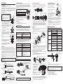
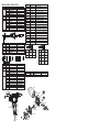
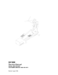
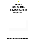
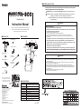
■ WARNINGS AND CAUTIONS
Warnings, cautions and notes are placed at critical points in this manual to direct the operator’s
attention to significant items. They are defined as follows:
WARNING: Failure to comply with a WARNING may result in serious injury or death.
CAUTION : Failure to comply with a CAUTION may result in injury to the operator, or
damage to the items involved. Two examples are given below.
Desoldering Tool
NOTE : A NOTE indicates a procedure or point that is important to the process
being described.
Instruction Manual
WARNING
■ Safety considerations.
Thank you for purchasing the HAKKO FR-300 Desoldering Tool.
Please read this manual before operating the HAKKO FR-300.
Keep this manual readily accessible for reference.
■ PACKING LIST
Be very careful when handling the desoldering tool.
During operation, the tip of the nozzle will rise to a temperature of 350 - 500℃ / 660 - 930°F,and the
surrounding areas will become extremely hot.
• After use, remove the cord from the power outlet.
• Never leave a plugged-in desoldering tool next to flammable materials.
• Never wave or swing the desoldering tool around, as hot solder from the tip may fly off and cause injury.
• Be especially careful when other people are in the area. Warm them of the danger of being burned by the hot
desoldering tool.
■ PART NAMES
Pre-filter (ALUM) × 1
HAKKO FR-300 × 1
Heating element
Filter pipe
Pump cover
Nozzle
Iron holder (Simple type) × 1
Element cover
assembly
Joint cover
assembly
Ceramic paper filter
(L) × 2
Plug
Cleaning pin
for ø1 nozzle × 1
Trigger
Release
button
● To prevent accidents or damage to the HAKKO FR-300, be sure to observe the following:
Power switch
CAL
Nozzle changing tool ×1
CAUTION
● The HAKKO FR-300 is an electrical tool used to melt and absorb solder in order to free components from the printed
circuit boards, etc. The desoldering tool should not be used for any other purpose as this may damage the product or
cause an accident or injury.
● Be careful when handling the desoldering tool. Do not drop it or otherwise subject it to excessive shocks as this may
impair its performance or cause damage or failure.
● Because the desoldering tool is extremely hot during normal use, proper maintenance is essential. Read the
“MAINTENANCE” section of these instructions and clean the designated areas and/or replace parts when necessary.
● Use only genuine HAKKO FR-300 replacement parts. The use of other replacment parts may impair performance of
cause damage or injury.
● If the pump does not operate, immediately clean the nozzle and heater.
● The unit is for counter or workbench use only.
LED lamp
Cleaning pin for
heating core × 1
• This appliance can be used by children aged from 8 years and above and persons
with reduced physical, sensory or mental capabilities or lack of experience and
knowledge if they have been given supervision or instruction concerning use of the
appliance in safe way and understand the hazards involved.
• Children shall not play with the appliance.
• Cleaning and user maintenance shall not be made by children without supervision.
• Wait until the desoldering tool has cooled completely before putting it away.
Temp. control knob
Instruction manual × 1
Protection cover × 1
* Before storing the unit in the carrying
case, be sure to insert the nozzle into
the protection cover to prevent risk of
a burn and melting the carrying case.
Protection
cover
HEAD OFFICE
4-5, Shiokusa 2-chome, Naniwa-ku, Osaka 556-0024 JAPAN
TEL:+81-6-6561-3225 FAX:+81-6-6561-8466
http://www.hakko.com E-mail:[email protected]
OVERSEAS AFFILIATES
U.S.A.: AMERICAN HAKKO PRODUCTS, INC.
TEL: (661) 294-0090 FAX: (661) 294-0096
Toll Free (800)88-HAKKO
4 2 5 5 6
http://www.hakkousa.com
HONG KONG: HAKKO DEVELOPMENT CO., LTD.
TEL: 2811-5588 FAX: 2590-0217
http://www.hakko.com.hk
E-mail:[email protected]
SINGAPORE: HAKKO PRODUCTS PTE., LTD.
TEL: 6748-2277 FAX: 6744-0033
http://www.hakko.com.sg
E-mail:[email protected]
Please access to the following address for the other Sales affiliates.
http://www.hakko.com
Copyright © 2015 HAKKO Corporation. All Rights Reserved.
Carrying case
Carrying case
■ SPECIFICATIONS
Power consumption 100V 98W (50/60Hz) 110V 122W (50/60Hz) 120V 140W (60Hz)
220V 105W (50/60Hz) 230V 118W (50/60Hz) 240V 130W (50/60Hz)
Temperature range 350 - 500℃ (660 - 930℉)
Nozzle to ground potential < 2 mV
Nozzle to ground resistance < 2 Ω
Diaphragm pump
Vacuum generator
81kPa (610mmHg)
Vacuum pressure
11L / min
Suction flow
Dimensions
226 (H) × 210 (W)mm / 8.9 × 8.3 in.
Weight
0.52 kg / 1.1 lb.
Standard nozzle
ø1.0 mm / 0.04 in. (Part No. N50-04)
*Specifications and design are subject to change without notice.
2015.4
MA02593XZ150414
泵組件
護艙
插頭
■ OPEARATION
D. Temperature setting
A. Preparation
1. Insert the plug of the power cord into an outlet.
2. Turn the power switch ON.
3. Wait for a few minutes until the nozzle will melt solder, then apply a generous
coating of your solder to the end of the nozzle. This prepares the nozzle for use
and helps reduce the chance of oxidation. Be sure to wait for at least 5 minutes
after tuning the tool on so that the heating core can heat up.
CAUTION
1. Place the nozzle over the lead wire of the
part to be desoldered and begin heating.
Nozzle
Board
Solder
Lead
Be careful to heat the lead wire and the
solder, not the land. Placing the nozzle
directly in contact with the land may cause
the land to peel off. You may apply a small
amount of solder to form a heat bridge to
help the heating process.
2. Check to make sure all of the solder on
the joint has melted.
With the nozzle still in place over the lead
wire, slowly move the lead wire, being
careful not to apply too much force. If the
lead wire moves easily, all of the solder
has melted.
Make sure that a filter has been inserted in
the desoldering tool. Desoldering without a
filter may damage the pump.
4. If the solder was not removed, re-solder
the part using new solder and then repeat
the desoldering process.
C. Cleaning
Cleaning is extremely important and should be done frequently during the
desoldering process. Parts should be checked periodically for wear and should
be replaced if necessary. See the MAINTANCE section of these instructions.
・Clean the nozzle as you would clean a soldering tip: wipe away any excess solder
with a sponge moistened with de-ionized or distilled water, or using a wire tip cleaner.
Before putting the desoldering tool away, apply a new coat of solder on the tip.
・Using a cleaning pin that matches the diameter of the nozzle, clean the inside of the
nozzle opening. This must be done while the nozzle and heating core are still hot, so
be careful.
・Discard any solder that has collected in the filter pipe. Do this carefully, as the solder
will still be extremely hot.
・Replace the filter. See the MAINTANCE section of these instructions.
The ceramic paper filter (L) should be replaced immediately when a stain appears or
vacuum decreases.
Failure to do this will reduce the performance of the pump and may damage it.
● Cleaning with cleaning pin
Approximate setting (on scale)
1
2
3∼4
・In general, the greater the temperature, the more quickly the
nozzle will oxidize and wear out.
・As nozzle oxidation and wear increases, the nozzle temperature
will decrease. In such cases, increasing the set temperature will
only accelerate oxidation and hasten wear.
Replace worn nozzles as soon as possible.
Heating core
Back holder
Low
High
1. Turn the power switch OFF.
2. Disconnect the plug of the power cord from an outlet.
MAINTENANCE
The frequency of cleaning and part replacement greatly depends on a variety
of factors, including the temperature at which the desoldering tool is
operated, and the types of solder and flux used. Using the table below as a
general guide, clean and replace parts in accordance with use conditions.
During use
Maintenance
Clean nozzle
Discard solder that has collected
Clean nozzle and heating core
Replace parts
Clean pump
A. A general guide to replacement part
Use the table below as a general guide to replacement part. Use only
genuine HAKKO FR-300 replacement parts as the use of other parts may
impair performance, or cause damage or injury.
Part Name
Pre-filter
Ceramic paper filter (L)
Front holder
Filter holder
Nozzle
Ceramic paper
filter (L)
Filter pipe
Signs that replacement is needed
Cannot hold solder
Warping
Hardened by flux staining
Hole has become enlarged
Hardening has reduced air tightness
Hardening had reduced air tightness
Repels solder
Solder plating on tip is gone
Clogging
Hole has corroded and is larger
Temperature is low
B. Replacing parts
Front holder
1. Install a new nozzle. The nozzle
being used may have already started
to wear, so use a new nozzle.
Low
high
Use a flathead screwdriver
to adjust
2. Insert the power plug into the outlet.
4. Wait for a few minutes.
Back holder
Pre-filter (ALUM)
Back holder
bushing
2. Inspect the parts shown in the diagram above. Clean and/or replace as needed.
3. During assembly, be sure to insert the filter. Failure to do so may
damage the unit. After the parts have been assembled, place the filter
pipe assembly into position and press the release button. The back
holder will spring forward and secure the filter pipe while creating a
vacuum seal.
● Pump
5. Use a soldering iron tip thermometer
to measure the temperature at the
end of the nozzle. Do not apply
suction, as this will cause the
temperature to drop.
6. Adjust the CAL trim pot with a calibration screwdriver or similar tool
until the temperature is 400℃ / 750°F. Turn the CAL trim pot clockwise
to increase the temperature and counter-clockwise to decrease
temperature.
・ It may take several minutes for the nozzle temperature to stabilize
after CAL is adjusted.
・ During CAL adjustment, make sure the set temperature does not go
above 500℃ / 930°F, as this may damage the desoldering tool.
TROUBLESHOOTING
Turn off the tool, remove the power plug from the power outlet and wait
until the unit has cooled completely.
1. Loosen the screws on the back of the pump cover and remove the pump
cover.
2. Remove the fixing plate.
Diaphragm
Fixing plate
Valve plate
Pump head
3. Clean the valve plate, fixing plate and pump head with isopropyl alcohol.
Align the notch on the pump head with the corresponding notch on the
valve plate.
Match the notch on the outside of the pump head with the one on the
fixing plate. Mount the diaphragm so that it is smooth and taut.
● Replacing the heating element (heating core)
Turn off the tool, remove the power plug from the outlet and wait until the
unit has cooled completely.
1. Remove the nozzle and element cover assembly with the nozzle
changing tool and remove the joint cover.
Remove the 2 screws.
Tool does not
heat up
Temperature is
low
Pump does not
operate
Suction force is
weak
Problem cause
Tool is not connected properly
to power outlet
Heating element burnout*
Sensor is broken*
Temperature is set too low
Temperature has not been
calibrated properly
Nozzle is worn out
Nozzle or heating core (in
heating element) is clogged
Too much solder or flux has
collected in the filter
Too much solder or flux has
collected in the filter or inner hose
Vacuum leakage
Pump valve or diaphragm is
broken
Procedure
Connect properly
Replace heating element
Reset
Calibrate properly
Replace nozzle
Clean
Replace filter
Replace filter or inner
hose
Inspect nozzle, area
around filter and pump
hose
Replace valve or
diaphragm
* Heater lead (Sensor lead)
Sensor(White:100 - 120V)
(Blue:220 - 240V)
Remove the joint cover.
● Nozzle
NOTE: Be careful since the areas around the nozzle and heating element are very hot.
1. Remove the element cover assembly and the nozzle with the attached wrench.
The element cover assembly is held
to the nozzle changing tool by pressing
this part from both sides.
Rotate the cleaning drill clockwise
while inserting, then pull straight out.
Scrape away all oxidation from the hole in the
heating element until the cleaning pin passes
cleanly through the hole.
CAUTION
The nozzle is not held to the nozzle changing tool. Be careful when removing them.
The cleaning pin passes cleanly and completely through the hole.
Filter pipe
Release button
Cleaning drill (optional)
● Clean the heating core
1. Pull the rear holder back until it clicks (locks into place) and remove
the filter pipe.
C. Calibrating the temperature
3. Set the temperature to 400℃/ 750°F.
E. After use
The cleaning pin passes completely
through the hole.
● Cleaning with cleaning drill
Be careful since the area around the filter pipe is extremely hot.
CAUTION
When necessary
Periodically
3. Pull the trigger to remove the melted
solder.
● Filter Pipe and related parts
Change the temperature only with the “TEMP” adjustment dial.
Do not use the “CAL” trim pot.
Type of board
Single-sided P.W.B.
Through-hole P.W.B.
Multilayer P.W.B
B. Desoldering
・If the pump does not operate, immediately clean
the nozzle & heating element and replace the
filter if necessary.
・Do not remove the pump cover during use. The
pump rotates at a high speed and can be
dangerous.
The temperature of the HAKKO FR-300 can be adjusted between 350 - 500
℃ / 660 - 930°F. Set the temperature in accordance with the requirements of
the job being done. Although the temperature needed for desoldering cannot
be determined merely by the type of board to be desoldered, the values in the
table below may be used as a general guide:
Flange
2 screws (Flange)
2. Loosen the screw at the back of the pump cover and remove the pump cover.
3. Remove the 6 screws from the
handpiece (including 2 screws
at the flange) and carefully
separate the housing.
4. Disconnect the heating
element terminal and
Push
replace the heating
Be careful of the spring
Terminal
element.
when opening the tool
to replace the heating
5. Assemble using the same
element.
procedure in reverse.
6. Calibrate the nozzle temperature.
Be sure to calibrate the nozzle temperature after replacing the heating element.
Failure to do this may result in a heater temperature that is much higher or
lower than the previous one, and can contribute to accelerated oxidation and/or
wear of the nozzle, or premature failure of the heating element.
Heater(Red)
*At 23℃/73°F,
Normal heater resistance value : 35Ω (100 - 120V models) 160Ω (220 - 240V models)
Normal sensor resistance value : 50Ω (100 - 120V, 220 - 240V models)
NOTE:
Use of the tool when the nozzle, heating core, or filter is clogged may cause the
pump to lock up and render operation impossible. Clean or otherwise eliminate the
blockage before attempting to use the tool.
Repairs
When repair becomes necessary, check the following and then bring the desoldering
tool to a HAKKO sales outlet or HAKKO dealer.
1. Is the nozzle or heating core clogged?
2. Is the valve plate cracked or missing?
3. Is the front holder or filter holder warped or cracked?
4. Is the pre-filter or ceramic paper filter dirty or warped?
⑥
①
②
Item No.
①
②
③
④
⑤
⑥
①
Part No.
B5019
B5020
A1033
B5016
B5017
A1217
Item No.
①
②
③
④
⑤
Part No.
B5018
B5021
B5022
B5010
B5011
B5012
B5013
B5026
B5027
B5028
B5029
B5030
B5031
B5033
B5034
ø0.8 mm (0.03 in.)
ø1.0 mm (0.04 in.)
ø0.8 mm (0.03 in.)
ø1.0 mm (0.04 in.)
ø1.3 mm (0.05 in.)
ø1.6 mm (0.06 in.)
④
⑤
Part Name
Back holder
Back holder bushing
Ceramic paper filter (L)
Pre-filter (ALUM)
Filter pipe
Front holder
③
②
③
Specifications
100V - 110V
120V
127V
220V - 240V
⑥
Specifications
10pcs.
5pcs.
④
⑤
Part Name
Inner hose
Housing
Trigger
P.W.B. / 100 - 110V
P.W.B. / 120V
P.W.B. / 220 - 230V
P.W.B. / 240V
øA
øB
N50-01
0.8 mm
(0.03 in.)
2.0 mm
(0.08 in.)
N50-02
1.0 mm
(0.04 in.)
2.0 mm
(0.08 in.)
Part No.
Item No.
①
②
Power cord, 3-wire cord but no plug
Power cord, 3-wire cord & European plug
Power cord, 3-wire cord & SI plug
Power cord, 3-wire cord & BS plug
Power cord, 3-wire cord & Australian plug
Power cord, 3-wire cord & American plug
Power cord, 3-wire cord & BS plug
With cord bushing
With cord bushing
With cord bushing
With cord bushing
With cord bushing
With cord bushing
With cord bushing UL
With cord bushing CE
Part No.
B5023
B5024
øA
øB
N50-03
0.8 mm
(0.03 in.)
2.5 mm
(0.10 in.)
N50-04
1.0 mm
(0.04 in.)
2.5 mm
(0.10 in.)
N50-05
1.3 mm
(0.05 in.)
3.0 mm
(0.12 in.)
N50-06
1.6 mm
(0.06 in.)
3.0 mm
(0.10 in.)
Specifications
Power cord, 3-wire cord & American plug
Cover
Part No.
⑥
Simple type
Optional
øA
⑤
Part Name
Heating element
Heating element
Heating element
Heating element
Movable joint
Wave spring
Joint cover
Nozzle S
Nozzle S
Nozzle
Nozzle
Nozzle
Nozzle
Element cover
Specifications
For heating element
For ø0.8 mm (0.03 in.) nozzle
For ø1.0 mm (0.04 in.) nozzle
For ø1.3 mm (0.05 in.) nozzle
For ø1.6 mm (0.06 in.) nozzle
For ø0.8 mm (0.03 in.) nozzle
For ø1.0 mm (0.04 in.) nozzle
For ø1.3 mm (0.05 in.) nozzle
For ø1.6 mm (0.06 in.) nozzle
For ø0.8 mm (0.03 in.)/1.0 mm (0.04 in.) nozzle
For ø1.3 mm (0.05 in.)/1.6 mm (0.06 in.) nozzle
For ø0.8 mm (0.03 in.) nozzle (set of 10)
For ø1.0 mm (0.04 in.) nozzle (set of 10)
For ø1.3 mm (0.05 in.) nozzle (set of 10)
For ø1.6 mm (0.06 in.) nozzle (set of 10)
øB
②
③
④
Part No.
A5025
A5000
A5021
A5001
B5063
B5064
B5062
N50-01
N50-02
N50-03
N50-04
N50-05
N50-06
B5014
øB
Item No.
①
Part Name
Cleaning pin
Cleaning pin
Cleaning pin
Cleaning pin
Cleaning pin
Cleaning drill
Cleaning drill
Cleaning drill
Cleaning drill
Drill holder
Drill holder
Drill bit
Drill bit
Drill bit
Drill bit
Adapter
Nozzle changing tool
Carrying case
Iron holder
Iron holder
Cleaning sponge
Part No.
B1085
B1086
B1087
B1088
B1089
B1302
B1303
B1304
B1305
B1306
B1307
B1308
B1309
B1310
B1311
B1356
B5015
C5000
C5003
C1100
A1042
øA
■ REPLACEMENT PARTS/OPTION
Part Name
Valve plate
Diaphragm
Specifications
Motor
①
Pump frame
Screw
Pump assembly
Crank shaft
③
Power switch
Diaphragm
setting plate
②
④
①
Cord
bushing
⑤
Fixing plate
Pump head
②
Crank
Spacer