1
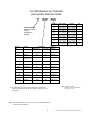
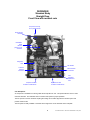
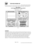
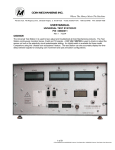
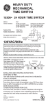
Where The Money Meets The Machine
PO Box 5128, 400 Regency Drive, Glendale Heights, IL 60139-5128
VOICE: 630/924-7070 1-800-323-6498
FAX: 630/924-7088
DEFENDER
USER MANUAL
•
•
•
•
•
•
•
•
Interchangeable with existing Comparitor®
mechanisms
Uses independent diameter sensing that
discriminates shaved coins or tokens
An array of sensors track the passage of
the coin from the moment it enters the
Defender until it exits
Micro controller based technology performs
coin analysis and I/O functions
Fixed credit buffering
Bi-color LED status indicator
Accurate coin counting at a feed rate up to
1 coin every 50 milliseconds
All mechanisms 100% coin tested before
shipment
•
•
•
•
•
•
•
1
Socketed micro for easy upgrades
Multiple Defender part numbers cover coin diameters
of .698” / 17.73 mm (U.S. Dime) through 1.50” /
38.10 mm.
Dynamic coin path sensing can determine if a
validated coin changes direction.
Coin Mechanisms, Inc. proprietary coin path
sensor.
An output (Ready) indicates the operating status
of the mechanism, and operates in conjunction with
the Bi-colored LED.
Optic emulation capabilities.
High or Low logic Inhibit available
© Coin Mechanisms Inc. Document # 09300339 Rev 1 May 2003
DEFENDER
BASIC THEORY OF OPERATION
BASIC THEORY OF OPERATION:
The DEFENDER is an Electromechanical Coin Mechanism designed to accept a single denomination metal coin.
The DEFENDER must be mounted in an up-right position so that gravity pulls a coin downward through the mechanism.
The mechanism has a single top coin entry slot located on the top left side. There are two coin exits at the bottom of
the mechanism. In a normal straight drop unit an accepted good coin exits the mechanism on the left side, directly
below the top entry slot, and rejected bad coins exit on the right side. In a reverse logic mechanism, an accepted
good coin exits the mechanism on the bottom right side, the side opposite of the top entry slot.
Inside the mechanism there is an Accept Gate. If a valid good coin is detected, the Accept Gate is opened
allowing the coin to fall out the bottom of the unit on the accept side. In reject mode, a bad coin is deflected by the Accept
Gate and falls out of the bottom of the mechanism on the reject side.
A representative sample of the coins that are to be accepted by the Comparitor must be placed in a special slot in the
magnetic sensor coils. This coin, and location, is referred to as the resident coin. The diameter of the resident coin and the
rail adjustment screw sets the drop slot width. The metal in the resident coin is used to compare against the metal of coins
falling through the mechanism.
The main circuit board in the DEFENDER interfaces with the Host Machine and Sensors located in the Mechanism.
A microcontroller on the main circuit board is controlled by special software that analyzes inputs from the sensors,
controls the Accept Gate, and issues the appropriate signals to the customer interface.
When a coin is dropped into the DEFENDER Mechanism, a microcontroller on the main PC board checks for specific
events to occur in the proper sequence for a proper length of time and then performs certain actions based
upon the event sequence.
NORMAL Event / Action Sequence.
=======================================
1)
Event:
Detect valid coin
2)
Action:
Open the Accept Gate and Issue Sense Pulse
3)
Event:
Detect coin exiting the mechanism
4)
Action:
Issue Credit Pulse and Close the Accept Gate
The Mechanism will automatically enter a TILT Mode if a sensor is blocked for too long, or if an improper sequence
of events is detected.
There is an Inhibit input on the Mechanism that will stop the unit from accepting coins when active.
2
© Coin Mechanisms Inc. Document # 09300339 Rev 1 May 2003
Coin Mechanisms Inc. Defender
part number Selection Guide
71
XXX
XXX
Mechanical
ID #
012
Defender Product
Family
Identification
Number
013
014
015
016
017
018
Machine
Mfr.
Aristocrat
Replaces
Model 62
Firmware ID #
(Small Coin)
(Large Coin)
005
006
Thickness
Range in. (mm)
0.050 - 0.065
(1.27 - 1.66mm)
0.066 - 0.085
(1.67 - 2.16mm)
0.086 - 0.125
(2.18 - 3.17mm)
0.066 - 0.085
(1.67 - 2.16mm)
0.086 - 0.125
(2.18 - 3.17mm)
0.066 - 0.085
(1.67 - 2.16mm)
0.086 - 0.125
(2.18 - 3.17mm)
Exit
Spacer
Y
Y
Y
N
N
N
N
Interface
Harness
0928-000117
Bally
Model 16OE
007
008
0928-000149
Bally
Model 62
005
006
0928-000117
Model 16
001
002
0928-000116
IGT
Diameter Range
in. (mm)
0.698 - 1.050
(17.7 - 26.6mm)
0.698 - 1.050
(17.7 - 26.6mm)
0.698 - 1.050
(17.7 - 26.6mm)
1.051 - 1.250
(26.7 - 31.7mm)
1.051 - 1.250
(26.7 - 31.7mm)
1.251 - 1.500
(31.8 - 38.1mm)
1.251 - 1.500
(31.8 - 38.1mm)
(80960 platform)
Konami
Model 40
009
010
0928-000117
Sigma
Model 16
009
010
0928-000115
Sigma
Model 16OE
011
012
0928-000117
Sigma
Model 40
013
014
0928-000126
W MS
Model 16
009
010
0928-000115
W MS
Model 40OE
003
004
0928-000117
Unidesa
Model 62
005
006
0928-000117
Universal
Model 62
005
006
0928-000117
e.g. Coin Mechanisms Inc part number 71001013 is a Defender that
will accommodate a U.S. 25 cent coin (0.955” x .069”) for use in an
IGT machine.
Note: Coin Size Description
Small coin = .698 - 1.250 diameter
Large coin = >1.251
Note: For specific parameters of each firmware, contact Coin Mechanisms Inc
customer service department.
3
© Coin Mechanisms Inc. Document # 09300339 Rev 1 May 2003
DEFENDER
Mechanical Specification
Mounting:
Within 3 degree of vertical
Drop Slot:
• The drop slot width is determined by the coin inserted as the resident coin. The resident coin must be
typical of the population of coins you want to accept. Do not use damaged, bent or excessively worn coin as
a resident coin.
• The drop slot width, or Diameter sensitivity, is fine tuned by adjusting the .050” hex set screw in the side rail.
• The coin/token must be delivered into the Defender drop slot within 6 degrees of vertical.
Drop Slot Alignment to Host Machine:
• In order to alleviate shingling of coins within the mechanism (and avoid jam conditions), the drop slot width
(coin thickness gap) is tightly controlled for ranges of coin thicknesses. This gap is maintained throughout
the mechanism.
• Coin head alignment to the Defender drop slot is crucial for proper operation. Misalignment can cause coin
jams at entry, coin delay causing Tilts, or erratic operation. Coins must be delivered into the mech opening
within 6 degrees of vertical to prevent fast feed jams at this opening.
• It is imperative that the host machine deliver coins into the Defender by referencing the centerline of the
mounting studs to the inside surface of the metal mainplate. This .25” / 6.3mm reference dimension has not
changed since mechanical mechanism usage. This alignment dimension is important because the
reference is the same regardless of the drop slot gap that is available in different Defender models. This
fixed reference is shown in the Defender mechanical specification section of the manual.
Resident Coin Insertion:
• The resident coin is used to “program” the Defender to accept that coin. The resident coin also
automatically sets the drop slot diameter clearance and sensor positions.
• The sliding Sensor Coil Assembly allows a wide range of diameter coins to be used without the need to add
or change parts to the mechanism.
• It is important for the resident coin to be centered in its rest position relative to the Sensor Coil. The resident
coin rests into a small notch on each side of its horizontal centerline. A self aligning guide designed into the
side walls will roll most resident coins into this proper location. Some coins may be difficult to “self align”.
Manually position these coins so they rest into the notch centerline. A resident coin that is not positioned
properly will most likely reject good coins.
Rail adjustment:
• A coin representative of the desired coin population is placed in residence.
• The rail adjustment is adjusted to accept 100% of the coins that match the resident coin.
• The diameter detection optics are designed to ACCEPT falling coins that are up to .010” / .254mm smaller in
diameter than the maximum diameter coin that the drop slot is set for.
• The diameter detection optics are designed to REJECT falling coins that are greater than .040” / 1.016mm
(smaller) in diameter than the maximum diameter coin that the drop slot is set for.
NOTE:
The diameter sensitivity set screw must never be turned more than 3/4 turn clockwise from its initial factory
setting to prevent damage to this assembly.
4
© Coin Mechanisms Inc. Document # 09300339 Rev 1 May 2003
DEFENDER
Standard Body
Straight Drop
Front View with resident coin
Drop Slot Coin Entry
on Top of Mechanism
Sliding Sensor
Coil Stack
RESIDENT
COIN
Must be
placed on coil
centerline
Diagnostic
LED
Test Header
Customer
Interface
Connector
Microcontroller
& Firmware
Coin
Sensitivity
Adjustment
POT
Accepted Coin Exit
on Bottom of Mechanism
Rejected Coin Exit
on Bottom of Mechanism
Coin Exit Spacer
An exit spacer is available for mounting inside the accept side coin exit. This spacer will limit coins to 1.050”
maximum diameter. The Defender does not need an exit spacer for proper operation.
The exit spacer is used in machines requiring the exiting coin to better align with the machine optics and
prevent nuisance Tilts.
The exit spacer is easily installed or removed with a single screw on the back side of the mainplate.
5
© Coin Mechanisms Inc. Document # 09300339 Rev 1 May 2003
DEFENDER
Mechanical Specification
Standard Body Straight Drop
Counter clockwise adjustment
of set screw reduces diameter
clearance in drop slot. Clockwise
increases clearance
A 1/4 turn of this screw changes
diameter clearance by
approximately.006” (.152mm)
6
© Coin Mechanisms Inc. Document # 09300339 Rev 1 May 2003
DEFENDER
Mechanical Alignment Specification
with exit spacer
Mechanical Dimension for mechanical fit only NOT COIN DIAMETER RANGE
FIXED
REFERENCE
FROM SIDE
FIXED REFERENCE
INSIDE SURFACE
OF MAINPLATE
Gap thickness for Defender units with exit spacer
Defender Model Description
71 XXX XXX
012
013
014
Entry
“A”
.085 in / 2.16 mm
.102 in / 2.59 mm
.130 in / 3.30 mm
EXIT
“B”
.090 in / 2.29 mm
.090 in / 2.29 mm
.130 in / 3.30 mm
Mechanical Dimension for mechanical fit only NOT COIN DIAMETER RANGE
FIXED REFERENCE
INSIDE SURFACE
OF MAINPLATE
7
© Coin Mechanisms Inc. Document # 09300339 Rev 1 May 2003
DEFENDER
Mechanical Alignment Specification
without exit spacer
Mechanical Dimension for mechanical fit only NOT COIN DIAMETER RANGE
FIXED
REFERENCE
FROM SIDE
FIXED REFERENCE
INSIDE SURFACE
OF MAINPLATE
Gap thickness for Defender units without exit spacer
Defender Model Description
71 XXX XXX
015 , 017
016 , 018
Entry
“A”
.102 in / 2.59 mm
.130 in / 3.30 mm
EXIT
“B”
.090 in / 2.29 mm
.130 in / 3.30 mm
Mechanical Dimension for mechanical fit only NOT COIN DIAMETER RANGE
FIXED REFERENCE
INSIDE SURFACE
OF MAINPLATE
8
© Coin Mechanisms Inc. Document # 09300339 Rev 1 May 2003
DEFENDER
INITIAL Configuration and Set-Up
The mechanism will ship from Coin Mechanisms in a normal operating configuration.
It may be necessary for the end user to make some special adjustments for their application.
Before installing the mechanism and powering it up the end user must:
1) Insert a sample coin in the resident coin location.
Note: When changing coin denominations, it may be necessary to adjust the rail adjustment screw.
2) Adjustment of the coin path diameter by using the rail adjustment screw :
Drop a coin, identical to the sample coin, through the Sense coils while turning the rail set screw
counterclockwise until Test coin(s) stops in the Sensor coil. *Slowly turn set screw clockwise until the
stopped coin falls through the mechanism. Drop more test coins and continue adjusting the rail set
screw
until all of the test coins drop completely through the mechanism. Turn screw an additional 1/4 turn for
diameter clearance, verify all good coins are accepted by the mechanism. Never turn screw more than
3/4
turn clockwise beyond initial minimum diameter clearance.
* If you cannot stop the test coin(s) in the Sensor coils, your resident coin may be greater than .009” in
diameter than your test coins or your resident coin is not seated properly in the holder notch. Select a
more typical size resident coin.
During Installation:
1) Connect an appropriate Cable to the 8-pin Customer Interface J1.
2) Apply 12VDC Power and make sure GREEN LED comes ON.
3) Drop valid coins through the unit and make sure they are properly accepted.
After Installation, During Normal Operation:
1) Adjust coin sensitivity POT.
Periodic Maintenance:
1) Make sure unit is Clean
No dust, dirt, or debris, has accumulated in the mechanisms drop slot.
2) Check Coil Balance.
3) Check Side Rail diameter Adjustment.
TOOLS REQUIRED
1) 0.050” Hex Wrench to adjust the Side-Rail Set Screw (CMI# 05090023).
2) 1/16 Hex Wrench to adjust Coil Balance (CMI # 05090004).
3) 3/32 Hex Wrench for Sensor Coil stack screws and Rail Assembly.
4) #1 Philips Screwdriver to remove Main PC Board.
5) #1 Flat Blade (2.0mm) Screwdriver to Set Pot on Main PC Board
6) ¼” Nut Driver to remove Tape Sensor & Sensor Coil KEPS Nuts
7) Sense coil gauge (CMI #04700026 .095” thick units, 04700027 for .130” thick units)
Conversion Interfaces
CMI P/N
0928-000113
0928-000115
0928-000116
0928-000117
0928-000126
0928-000118
0928-000147
0928-000149
0928-000150
0928-000151
Interface Description
8 pin JST connector to flying lead interface
8 pin JST connector to Six pin JST(all model 16)
8 pin JST connector to Six pin Molex (IGT 80960)
8 pin JST connector to Seven pin Molex (all model 62/WMS Optic
Emulation)
8 pin JST connector to Six pin JST(all model 40)
8 pin JST connector to 4 pin & 2 pin Molex (Sigma Optic emulation)
12 pin Molex to flying lead Test Header interface
8 pin JST connector to 24-12 VDC converter board (Ballys optic emulation)
8 pin JST connector to 15 pin Molex & 2 pin Molex (IGT Optic emulation)
12 pin Molex to 3 wire flying lead test header interface
9
© Coin Mechanisms Inc. Document # 09300339 Rev 1 May 2003
DEFENDER
PCB Electrical Specifications
Sensitivity Pot:
Environmental:
Used to adjust the metal match between the Resident coin and the
coin to be accepted.
Full Clockwise
= 1 o’clock = Poor Metal Match between coins
Mid Range
Operating temp.
Storage temp.
Non-Condensing Humidity Range
0 to 60 degree C
-40 to 80 degree C
10%-90%
= 9 o’clock = Average Metal Match between coins
Full Counter Clockwise = 5 o’clock = Best Metal Match between coins
INHIBIT:
The basic function of the Inhibit circuit is to detect an external connection to ground. The Inhibit control lead is designed to be connected
to a switch, or relay contact, that makes and breaks a connection to ground. An open-collector transistor driver can also be connected to
the Defender Inhibit input. Internally the Inhibit circuit is pulled up to the power input voltage by a resistor. Therefore, when the Inhibit
control lead is floating a voltage is present on the Inhibit lead. Diodes block positive voltage from entering the circuit, and prevent the
Inhibit input from being pulled below ground. An open, unconnected Inhibit control lead is treated as a Logic High. Shorting the Inhibit
control lead to Ground is treated as a Logic Low.
Customer Interface
WIRE
COLOR
FUNCTION
1
BLACK
WIRE
GROUND
2
BLUE WIRE
3
Test Header
V Max.
V Min.
I Max.
INHIBIT
Control Lead
24 to 4.5 V
Logic High
3.0 to 0.0V
Logic Low
- 5 mA
WHITE WIRE
READY (Open Collector)
Normally Low
30V DC
4V DC
100 mA
1 mA
GRAY WIRE
TILT (Open Collector)
Normally High
30V DC
4V DC
100 mA
1 mA
GREEN WIRE
CREDIT (Open Collector)
Normally High
30V DC
4V DC
100 mA
1 mA
6
YELLOW WIRE
SENSE (Open Collector)
Normally High
30V DC
4V DC
100 mA
1 mA
7
RED WIRE
+12V POWER IN
15V DC
11V DC
500 mA
50 mA
VIOLET WIRE
SENSE (Sourcing)
Normally Low
Power In
--
-15 mA
5
2
3
4
5
6
7
8
9
10
11
12
WHT / BRN
POT
WIRE
Mating Connector: JST XHP-8 CMI # 0826-003041
Connector Configuration
TOP VIEW
06270048 Tape
Sensor Assembly
0927-000510
Board
06270049 Exit
Optics LED
Assembly
0927-000511
Board
06250134
Accept Coil
Assembly
GROUND
1
BLACK
WIRE
8
RAW
NULL
4
I Min.
GRN / YEL
WIRE
PIN
#
Green Wire
Green Wire
Black Wire
Red Wire
Black Wire
Yellow Wire
Red Wire
Green Wire
Plastic
Housing
Orange Wire
Red Wire
Brown Wire
White Wire
Blue Wire
Yellow Wire
Black Wire
Black Wire
Green Wire
Gray Wire
Black Wire
Yellow Wire
06270054 Rail Optic
Assembly
0927-000518 Board
Coil Stack Assembly
10
© Coin Mechanisms Inc. Document # 09300339 Rev 1 May 2003
DEFENDER
MAGNETIC SENSING COIL AIR BALANCE
PROCEDURE with Oscilloscope
Air balancing the magnetic sensor coils is an important adjustment and must be done to every Mechanism.
When you adjust the coil balance set screws you are adjusting the physical spacing between the magnetic coils. It is
important to space the coils an equal distance apart to create equal magnetic fields in the front resident coin gap and in the
rear drop slot gap.
1)
Remove power from the Mechanism.
2)
Remove the Resident Coin, if present.
COIL BALANCE
SET SCREW
SENSOR
COIL
3)
There is a front (resident coin) coil balance set screw, and a back (drop slot) coil
STACK
balance set screw. Use a 1/16 Inch Hex Wrench Adjustment tool (CMI # 05090004)
SCREWS
and loosen the front resident coil and back drop slot coil balance setscrews.
4) Use a 3/32 Inch Torque Driver set to 3 1/2 Inch Pounds, verify the torque on the
two screws that hold the coil stack together are torqued down to 3 1/2 Inch Pounds.
5) Insert a small plastic poker chip (CMI # 04090014) in the resident coin location.
6) Place the Mechanism in a test stand (CMI # 05000009).
7) Use a12-Pin Test Header Cable (CMI # 0928-000151).
Connect an Oscilloscope to Pin 5 (Raw Null) on the Test Header.
Connect the Oscilloscope Probe Ground to Pin 6 (Ground) on the Test Header.
8) Set the Oscilloscope to:
Horizontal Time base to 100uS per Division.
Vertical Display to 100 mV per Division.
9) Apply power to the Mechanism.
10) Look at the Oscilloscope display. It should be displaying the Raw Null Signal, an AC waveform that can oscillate
between 7 and 9 KHz and can have an amplitude of about 9 volts Peak-to-Peak maximum, and go down to about 50
millivolts minimum. You may have to adjust your oscilloscope to properly view the waveform.
WITHOUT GAUGE BAR
11) Using the Hex Wrench Adjustment tool, slowly tighten the front (resident coin) coil balance set screw to the point where
the setscrew just bottoms out and gets a little hard to turn. Do not over tighten this setscrew.
WITH COIL GAP GAUGE BAR
11) Using the Hex Wrench Adjustment tool, slowly tighten the front (resident coin) coil balance set screw to the point where
the DEFENDER (.095 for Thin Coin) Coil Gap Gage Bar just slips between the front coil and center coil (where the
resident coin would be located). Do not over tighten this setscrew. Remove the Gage Bar and place the plastic poker
chip in the resident coin location.
12) Using the Hex Wrench Adjustment tool, slowly tighten, or adjust, the rear (drop slot) coil balance set screw to achieve
the smallest possible Raw Null signal level.
A good mechanism should achieve an air coil balance Raw Null signal level of less than 700 mV Peak-to-Peak, or less than
400 mV Positive Peak to Ground.
If a good air coil balance cannot be achieved, then there could be a problem with the coil set or the main PC board. In most
cases if a good coil air balance cannot be achieved then the Sensor Coil Assembly needs to be replaced. However,
occasionally other items can cause a problem, and sometimes the main PC Board must be replaced.
13) After making the coil balance adjustment, remove power from the Mechanism.
If you are finished testing the mechanism then disconnect the oscilloscope and Test Header Cable. Replace the Resident
coin.
NOTE: It is recommended that the side rail set screw adjustment be checked each time the coils are balanced.
11
© Coin Mechanisms Inc. Document # 09300339 Rev 1 May 2003