1
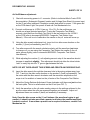
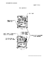
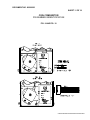
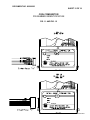
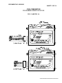
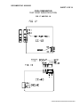
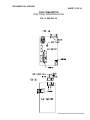
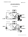
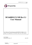
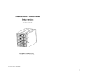
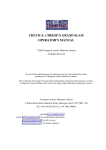
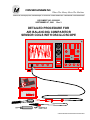
Where The Money Meets The Machine
PO Box 5128, 400 Regency Drive, Glendale Heights, IL 60139-5128
VOICE: 630/924-7070 1-800-323-6498
FAX: 630/924-7088
DOCUMENT NO. 09300083
SEPTEMBER 27, 2001 Rev. 3
DETAILED PROCEDURE FOR
AIR BALANCING COMPARITOR
SENSOR COILS WITH OSCILLOSCOPE
COIN COMPARITOR
CC-16-D
G:\DOC\PROCED\09300083\REV3\09300083.DOC
DOCUMENT NO. 09300083
SHEET 2 OF 19
DETAILED PROCEDURE FOR
AIR BALANCING THE SENSOR COILS
WITH OSCILLOSCOPE
INTRODUCTION:
Air balancing the sensor coils is one of the most important adjustments made to the Coin
Comparitor. Air balancing simply means to adjust the gap between the coils, to create an
electrical field that is equal in both coin slots. It is important to adjust both coil sensor
screws on the CC product line to an equal depth into the sensor coil body. By following this
procedure, a uniform chamber gap will be maintained in the sensing area. Coin travel and
sensing metal content of coins and tokens can be made more accurately. In addition,
proper rail insert adjustment will complete the air balance procedure by providing a means
to match the resident coin to the falling coin so they “eclipse” in the sensor coils. There is no
rail adjustment on the Intelligent Comparitor product line.
Another performance related adjustment is the selectivity potentiometer. Proper selectivity
adjustment will improve coin / token acceptance vs. slug rejection.
Pages 10 – 13 illustrates the input/output pin assignments for the various Coin Comparitors
that COIN MECHANISMS INC. manufactures.
WHY AIR BALANCE THE SENSOR COILS ?
1) After installing a new sensor coil assembly into a Comparitor.
2) After installing a rebuilt sensor coil assembly into a Comparitor.
3) Typical maintenance procedure for optimum performance.
ACCESSORIES
The following are accessories available from Coin Mechanisms Inc. or our authorized
distributor for powering your unit or assist in testing and/or adjusting a Coin Comparitor.
PART NUMBER
05000009
09280101
09280100
09280103
09280102
09300247
09300256
DESCRIPTION
Test Stand (See page 10 OF 19)
I/F,B,TS,COMPARITOR,3PIN JST,BLK/VIO/ORG
I/F,A,TS,COMPARITOR,6PIN JST, BLK,ORG,YEL, RED, BLU GRY
I/F,D,TS,COMPARITOR,7PIN MOLEX/AMP,YEL/RED/BLU /ORG/GRN/BLK
I/F,C,TS,COMPARITOR,6PIN MOLEX/AMP GRY/RED/BLU/YEL/ORG/BLK
VIDEO,VHS,COMPARITOR TRAINING
VIDEO,PAL,COMPARITOR TRAINING
TOOL LIST:
1) Various diameter, plastic tokens.
2) 1/16” hex allen head, adjusting screwdriver.
3) Coin sticks, or coins and scotch tape.
4) Comparitor Test Station, or power supply.
5) Oscilloscope, optional if using the Comparitor Test Station.
G:\DOC\PROCED\09300083\REV3\09300083.DOC
DOCUMENT NO. 09300083
SHEET 3 OF 19
AIR BALANCING PROCEDURES
FOR THE COIN COMPARITOR
AND MICRO COMPARITOR
Preliminary setup:
1)
Connect scope test probe to the “Test Point”, (see pg.14 - 19). Illustrations show
a CC-16, CC-40, CC-46/MC, CC-62, CC-33/37, CC-32/36 Comparitors and
Intelligent Comparitors for “Test Point” location = pin 7 op-amp output. IC
model is shown on pages 18 and 19. Refer to individual Mech Control PCB
documentation (Schematic Diagram) for “Test Point” location and (Voltage
Spec Sheet) for power input to Comparitor models. Ground the scope ground
connection to the ground input for common ground. If using the Comparitor Test
Station connect a test lead from the Mech Test Point to the “Test Point” on the
PCB (refer to document #00300001 Comparitor Test Station User Manual).
2)
Set the Scope VOLT/DIV. to 500 mv. per division.
Set the Scope TIME/DIV to
1 ms. per division. Depending on type of scope,
some waveform positioning may be necessary to view the whole waveform.
Air Null Balance setup :
1)
Use the plastic token chip provided with Comparitor (similar in diameter) to the actual
coin or token to be used later as the sample coin and insert this chip into the sensor
coils “Sample Holder”, indicated by the label “Slide To Replace Coin”. The plastic
token positions the coils in their optimum location to simulate typical operating
conditions. (see FIG. 2).
For optimizing performance:
2) Using the 1/16” allen head screw driver, back out the sensor coil screws counterclockwise approximately two full turns. Check the Coil Mounting Screw holding the
sensor coils together for approximately 4-in. lb. of torque. Torque this screw to 4-in. lb.
if necessary then seat the allen screws as indicated in step 3. (See FIG.4).
For new or rebuilt sensor coil assemblies:
3) Using the 1/16” allen head screw driver, turn the Sensor Coil Adjusting Screws
clockwise (see FIG. 3) until screws just touch against the center coils metal plate stop.
Make sure both screws are seated with equal depth into the sensor coil body.
G:\DOC\PROCED\09300083\REV3\09300083.DOC
DOCUMENT NO. 09300083
SHEET 4 OF 19
Air Null Balance adjustment :
1)
Start with top screw first and alternate between top and bottom screws in short
intervals, with inward clockwise rotation, until achieving the smallest amplitude
of the waveform possible. Typically 80 to 200 mv. is considered to be a proper
null. If using the Comparitor Test Station, achieve the lowest µA reading on the
µA meter. (refer to document #00300001 Comparitor Test Station User
Manual).
Rail Insert adjustment setup:
1)
Remove the plastic chip token from the “Sample Holder”. Insert “Coin Sticks” into the
coils, using the allen screw driver turn the rail insert screw counter-clockwise until rail
insert is against the rail body, remove any slack in the assembly by applying light
pressure against the coils, towards the rail assembly (see FIG 4 & 5).
2)
If “Coin Sticks” are unavailable use the coin and tape method, insert coin into the
“Sample Holder“, remove slack, apply tape to second identical coin and lower it into the
other coil gap, position the taped coin in parallel to and “eclipse” the sample coin,
observe the waveform for lowest amplitude and tape coin in place onto the mainplate.
Rail Insert adjustment:
1) The rail insert adjustment allows you to optimize the position of the resident coin to the
falling coin. In order to get the best “comparison” of coins they need to “eclipse” each
other when they are in the center of the sensor coil. The rail insert adjustment allows
this exact match to occur. Performing this adjustment optimizes against fraud coins.
The adjustment also allows compensation for worn parts to bring a highly used
Comparitor back to optimum operating parameters.
2) Using the allen screw driver, turn screw slowly clockwise (see FIG. 4 & 5), observe the
waveform, it should lower in amplitude, keep adjusting clockwise until smallest
amplitude can be achieved. If using the Comparitor Test Station the lowest µA reading
on the µA meter is desirable (refer to document #00300001 Comparitor Test Station
User Manual). Remove sticks or taped coin after adjustment.
G:\DOC\PROCED\09300083\REV3\09300083.DOC
DOCUMENT NO. 09300083
SHEET 5 OF 19
Selectivity adjustment:
1)
Insert sample coin into “Sample Holder”. Turn Selectivity Adjustment Potentiometer
(see FIG.1 & 2) fully counter-clockwise (full accept position). Drop coins, all coins will
accept. Turn potentiometer fully clockwise (full reject position). Drop coins, all coins
will reject. To set for best performance for coin in residence which is the (sample coin),
turn pot back, counter-clockwise in short increments, dropping coins frequently between
turns, until coins begin to accept. Drop a good range of coins or tokens to make sure all
coins accept, fine tune as necessary to accept all good coins or tokens and reject fraud
coins.
AIR BALANCE PROCEDURES FOR THE
INTELLIGENT COMPARITOR PRODUCT LINE
Preliminary setup:
1)
Connect scope test probe to J4 PIN2 (see pg. 18 or 19) = pin 7 op-amp output.
Refer to individual Mech Control PCB documentation (Schematic Diagram) J4
location. Ground the scope ground connection to J4 PIN 6. If using the
Comparitor Test Station connect a test lead from the Mech Test Point on the test
station to the J4 PIN 2 on the PCB (refer to document #00300001 Comparitor
Test Station User Manual).
.
2)
Set the Scope VOLT/DIV. to 500 mv. per division.
Set the Scope TIME/DIV to
1 ms. per division. Depending on type of scope,
some waveform positioning may be necessary to view the whole waveform.
Air Null Balance setup :
For optimizing performance:
1) Using the 1/16” allen head screw driver, back out the Coil Adjustment Screws (see FIG.
6 & FIG. 7) counter- clockwise approximately two full turns. Check the Coil Mounting
Screws (see FIG. 6) holding the sensor coils together at approximately 3-1/2 in. lbs. of
torque. Verify the torque on the two screws that hold the sensing coil stack together
then seat the allen screws as indicated in step 2.
2)
For new or rebuilt sensor coil assemblies:
Using the 1/16” allen head screw driver, turn the Coil Adjustment Screws clockwise
(see FIG. 6 & FIG. 7) until screws just touch against the center coil metal pin stop.
Make sure both screws are seated with equal depth into the sensor coil body.
G:\DOC\PROCED\09300083\REV3\09300083.DOC
DOCUMENT NO. 09300083
SHEET 6 OF 19
Air Null Balance adjustment :
1)
2)
Start with connecting power to J1 connector (Refer to individual Mech Control PCB
documentation. (Schematic Diagram) location and (Voltage Spec Sheet) for power input
for the IC and other intelligent Comparitor models and switch on power. If the green led
on the PCB doesn’t light, turn power off and call Coin Mechanisms Inc.
Connect oscilloscope to J4 PIN 2 (see pg. 18 or 19). On the oscilloscope, you
should see a large distorted waveform. If using the Comparitor Test Station
connect a test lead from the Mech Test Point on the test station to the J4 PIN 2
on the PCB (refer to document #00300001 Comparitor Test Station User
Manual). If the unit is out of calibration the needle on the µA meter will move up.
3) Using the allen wrench adjustment tool, insert tool into allen screw location on the
number (1) (front) coil assembly (see FIG 6).
4) Turn allen screw with the wrench clockwise slowly until the waveform just starts
to change or if you are using the Comparitor Test Station the needle on the µA
meter moves slightly (refer to document #00300001 Comparitor Test Station
User Manual).
5) While adjusting the number (1) coil adjusting screw in step 4. the waveform should
increase in amplitude slightly. This adjustment should just allow the token holder
“web” to easily slip into the “V” groove gap between the coils.
NOTE: DO NOT OVER ADJUST THIS SCREW AND CREATE AN EXCESSIVE GAP.
6) Insert the allen wrench through the clearance hole in the spring retainer assy (see
FIG. 7) and into the allen screw location on the number 3 (back) coil assembly. Turn
the screw with the allen wrench clockwise until the waveform amplitude on the
scope is at it’s smallest or lowest on the µA meter of the Comparitor Test Station.
7) Adjust the Spring Retainer Adjustment Screw clockwise until the screw just touches
the main plate. This is to relieve strain on the #3 coil (see FIG. 7).
8) Verify the waveform or the µA meter reading returns to the settings achieved in the
previous steps when the coils are squeezed together and released. Adjust coil
adjustment screw on number 3 (back) coil assembly if necessary.
Note: Once the allen screw on the (1) coil bottoms (the waveform begins to get
smaller), it should not take more than a quarter turn before the smallest amplitude
has been reached. If more than a quarter turn is required to balance, contact Coin
Mechanism Inc.
G:\DOC\PROCED\09300083\REV3\09300083.DOC
DOCUMENT NO. 09300083
SHEET 7 OF 19
FIG. 1 AND FIG. 2
G:\DOC\PROCED\09300083\REV3\09300083.DOC
DOCUMENT NO. 09300083
SHEET 8 OF 19
FIG. 3, FIG. 4 AND FIG. 5
G:\DOC\PROCED\09300083\REV3\09300083.DOC
DOCUMENT NO. 09300083
SHEET 9 of 19
FIG. 6 AND FIG. 7
G:\DOC\PROCED\09300083\REV3\09300083.DOC
DOCUMENT NO. 09300083
SHEET 10 OF 19
FIG. 8
Test Stand
P/N 05000009
G:\DOC\PROCED\09300083\REV3\09300083.DOC
DOCUMENT NO. 09300083
SHEET 11 OF 19
COIN COMPARITOR
PIN NUMBER INDENTIFICATION
FIG. 9 AND FIG. 10
G:\DOC\PROCED\09300083\REV3\09300083.DOC
DOCUMENT NO. 09300083
SHEET 12 OF 19
COIN COMPARITOR
PIN NUMBER INDENTIFICATION
FIG. 11 AND FIG. 12
G:\DOC\PROCED\09300083\REV3\09300083.DOC
DOCUMENT NO. 09300083
SHEET 13 OF 19
COIN COMPARITOR
PIN NUMBER INDENTIFICATION
FIG. 13 AND FIG. 14
G:\DOC\PROCED\09300083\REV3\09300083.DOC
DOCUMENT NO. 09300083
SHEET 14 OF 19
COIN COMPARITOR
TEST POINT INDENTIFICATION
FIG. 15 AND FIG. 16
G:\DOC\PROCED\09300083\REV3\09300083.DOC
DOCUMENT NO. 09300083
SHEET 15 OF 19
COIN COMPARITOR
TEST POINT INDENTIFICATION
FIG. 17 AND FIG. 18
G:\DOC\PROCED\09300083\REV3\09300083.DOC
DOCUMENT NO. 09300083
SHEET 16 OF 19
COIN COMPARITOR
TEST POINT INDENTIFICATION
FIG. 19 AND FIG. 20
G:\DOC\PROCED\09300083\REV3\09300083.DOC
DOCUMENT NO. 09300083
SHEET 17 OF 19
MICRO COMPARITOR
TEST POINT INDENTIFICATION
FIG. 21 AND FIG. 22
G:\DOC\PROCED\09300083\REV3\09300083.DOC
DOCUMENT NO. 09300083
SHEET 18 OF 19
INTELLIGENT COMPARITOR
TEST POINT INDENTIFICATION
FIG. 23 AND FIG. 24
G:\DOC\PROCED\09300083\REV3\09300083.DOC
DOCUMENT NO. 09300083
SHEET 19 OF 19
INTELLIGENT COMPARITOR
TEST POINT INDENTIFICATION
FIG. 25 AND FIG. 26
G:\DOC\PROCED\09300083\REV3\09300083.DOC