1
K2
K1
C
D2
D1
NC
L2
L1
L
N
Puck Switch Terminal
Lamp 1 Lamp 2
Live
External Switch
+12V
------ Common
Netural
LOAD 1
LOAD 2
LED 2
LED 1
Button/Switch 2
Button/Switch 1
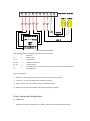
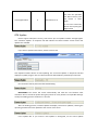
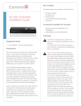
(Wire Configuration Figure)
Wiring Configuration, according to the silkscreen on the shell
L
------Line Wire
N
------Neutral Wire
L1, L2
------Load outputs
D1, D2 ------Indicator LED outputs
K1, K2 ------Contact inputs
C
------Common terminal, must be connected to 12V terminal on external switch
NC
------Not connected
Steps to installation
1) Short the ‘12V’ terminal and ‘common’ terminal on the auxiliary switch
2) Connect ‘C’ on the puck switch with ‘Common’ terminal
3) Match the ‘K1’,’K2’ with switch outputs on auxiliary switches
4) Match the ‘D1’,’D2’ with indicator LED inputs on auxiliary switches
Driver Setup and Configuration
1) Add Driver
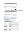
Device type is ‘others’, Manufacture is ‘inSona’, double click to add puck switch driver