1
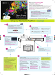
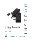
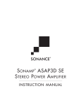
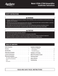
™
Box Contents
The following items are included in the HC-800 box:
• HC-800 Controller
HC-800 Controller
Installation Guide
• AC to DC power adapter with power cord
• IR emitters (6)
• Antennas (3): ZigBee (1) and dipole antennas (2)
for wireless (WiFi).
• Pluggable Contact/Relay connectors (2)
• Warranty Card
Accessories for Purchase
• Rack Ear Kit (C4-1UREK-B)
• 10’ Antenna Kit (C4-AK-3M)
Warnings
Supported Model
• C4-HC800-BL – HC-800 Controller, Black
Introduction
The Control4® HC-800 Controller (HC-800) provides
ways to control lights, home theaters, wholehome music and video systems, and other devices
controlled by IP, infrared (IR), Serial, Contact, or Relay
connections. The Controller has a fast processor,
built-in WiFi, HDMI for audio and video, improved
ZigBee radio, and more.
The HC-800 also provides extensive media
management support for audio and video content,
including CDs, DVDs, Blu-ray Discs, or digital media
stored in connected devices. You can use an external
storage device with USB, NAS, or eSATA connectivity,
and it supports multi-zone audio capabilities, sending
music to various rooms in the home. The device can
be stacked with AV devices or rack-mounted using
the optional rack ears.
After you install and configure the HC-800 (using
the Composer Pro software) along with the other
system components, your customers can control their
system using the On-Screen Navigator, the MyHome
app, System Remote Controls, Touch Screens, or any
other Control4-supported interface devices (sold
separately).
WARNING! To reduce the risk of electrical
shock, do not expose this apparatus to rain or
moisture.
AVERTISSEMENT! Pour réduire le risque de
choc électrique, n’exposez pas cet appareil à la
pluie ou à l’humidité.
WARNING! This CLASS I apparatus must
be connected to an AC mains socket outlet
that has a protective earthing connection
(e.g., third-prong ground conductor). DO
NOT DEFEAT THE PROTECTIVE EARTHING
CONNECTION!
AVERTISSEMENT! Cette appareil de classe I
doit être raccordé à une prise de courant qui
a une connexion Mise à la terre (par exemple,
conducteur avec troisième broche). NE PAS
DÉFAIRE LA CONNEXION DE MISE À LA
TERRE!
For general information about the product, see the
Product pages at http://www.control4.com.
Requirements and Specifications
Prior to installing the HC-800, ensure that Ethernet
network wiring is in place. If you’re using WiFi, see
“Antenna Considerations” which includes information
1
™
Additional Resources
The following resources are available for additional
support.
HC-800 Controller
Installation Guide
• Control4 Knowledgebase or Forums
• Control4 Technical Support
• Control4 website: http://www.control4.com
• Composer documentation in online help or PDF
format available on the Dealer portal (http://
dealer.control4.com/).
about ZigBee Access Points (ZAPs).
Front View
Figure 1. Front View
HC-800 Specifications
WIFI
Model Number
C4-HC800-BL
Network
- Ethernet—required
- WiFi (only supported when the
device is used as a Secondary
Controller)
Media Recognition
Online CD/DVD/Blu-ray
recognition and media information
service. Supports MP3, AAC, FLAC.
Video
HDMI 1.4 output; Component Video
output; SD 480I; HD 720p 50-60
Hz.
1
Colors for signal strength: Orange=Fair to Good,
Power Requirements
100-240 VAC, 60/50 Hz, 0.4A MAX
DC Input: 19V DC
2
Power Consumption
Max: 44W, 150 BTUs/hour
Idle: 24W, 82 BTUs/hour
3
Operating Temperature
3˚- 95˚ F (0˚ - 35˚ C)
Storage Temperature
-4˚ - 149˚ F (-20˚ - 65˚ C)
IR Out
5V 27mA, max/output
IR Capture
0-60KHz
Contacts
DC - 36V maximum operation (low
voltage)
The available current for 12V
contact outputs is 1.25A maximum,
shared across all outputs.
Weight
6.1 pounds (2.766 kg)
Shipping Weight
7.95 pounds (3.606 kg)
WiFi LED. This LED blinks Orange and then Blue
of its connection to its associated access point.
LED indicators
H x W x D: 2.80” (71 mm) x 11.98”
(304 mm) x 7.24” (184 mm)
4
the LED color depending on the signal strength
Display
Dimensions
3
system starts running, the WiFi driver changes
MP3: 32kbps to 320kbps, CBR,
VBR, AAC, and FLAC
AC - 36V, 2A
DC - 24V, 2A
Maximum operation (low voltage)
1
LINK
during the boot process. When the operating
Audio Playback Formats
Relays
2
5
2
DATA
Blue=Excellent, No Light=No connection or not
enabled, and Red=Poor signal strength.
Data LED. The Blue LED indicates that streaming
audio is received.
Link LED. The Blue LED indicates that the
Controller has been identified into a project.
4
Power LED. The Blue LED indicates that AC
power is present. The LED blinks during the boot
process.
5
IR Window/IR Blaster—For learning IR codes.
Back View
Connect all applicable devices to the HC-800 using
the connection options described next.
Figure 2. Back View
10 Digital Audio Out. Digital audio output jack
for stereo line output for amplifiers or audio
16
switches.
11 Audio Out. RCA jacks for stereo channel
line output (line level) for amplifiers or audio
4
1
2
8
6
5
7
10
9
3
12
11
14
17
switches.
12 Audio In. (One (1) pair). RCA jacks for stereo
18
13
15
channel input (line level) for one (1) stereo analog
19
source.
13 eSATA. External serial ATA port for connecting a
hard drive on which to store media. See “Setting
1
ZigBee. The antenna for the ZigBee radio.
up External Storage Devices” for information. For
information about eSATA storage limitations, see
NOTE: If you run ZigBee, use the external
antenna (provided).
eSATA Installation Guide in the Knowledgebase.
14 Ethernet. RJ-45 jack for a 10/100/1000 BaseT
Ethernet connection.
2
3
Power Plug Port. AC to DC power adapter for the
15 USB. For external storage device with USB
power cord.
support. See “Setting up External Storage
Factory Restore Button. A recessed button that
Devices” for information. For information
restores or resets the Controller to the factory
about USB storage limitations, see the eSATA
defaults. See “Troubleshooting” for details.
4
5
Identification Button. An easily-pressed button
Installation Guide in the Knowledgebase.
16 Relays. Pluggable terminal block connector for
used to identify this device in Composer Pro to
four (4) switchable connections, such as a blind,
revert the device back to Ethernet with its default
a fireplace, or a projector screen. The connectors
settings.
are for Normally Opened (NO), Normally Closed
RS-232 Serial. DB9 connectors for two (2) serial
(NC), and Common (COM).
devices, such as a receiver or disc changer. See
17 Power. For troubleshooting purposes only. After
“Connect the Serial Ports” for information.
6
transmitters. See “Set Up IR Emitters or IR
7
plugging in the HC-800, it it does not power on,
IR Out. 3.5 mm jacks for up to six (6) IR output
insert a paper clip into the pinhole to power it on.
18 Contacts. Pluggable terminal block connector for
Blaster” for information.
four (4) Normally Closed or Normally Opened
HDMI Out (Audio/Video). HDMI port for
switchable connections. Provides power for small
displaying navigation menus on a monitor or TV.
devices (12V), signal input (SIG), and return path
(GND).
NOTE: HDMI and Component cords can be
19 WiFi 2. Reverse SMA Connector to attach a WiFi
connected at the same time, but only one is
antenna.
active.
NOTES: (1) WiFi cannot be used for Primary
8
9
Video Out (Component). Component jack used
Controllers; use WiFi for Secondary Controllers
for displaying navigation menus on a monitor or
only. See “Antenna Considerations” below. (2)
TV.
For best results, we recommend that you use
WiFi 1. Reverse SMA connector to attach a WiFi
802.11 n.
antenna. Supports 802.11 b/g/n.
Installation Instructions
NOTES: (1) WiFi cannot be used for Primary
Controllers; use WiFi for Secondary Controllers
To install this Controller:
only. See “Antenna Considerations” below. (2)
For best results, we recommend that you use
802.11 n.
1
Ensure that your home network is in place before
starting your system setup. The HC-800 requires
a network connection (wired or WiFi) to use
3
all features as designed. When connected, the
To connect a device to the Pluggable Terminal Block:
Controller can connect to other IP devices on
the home network and access web-based media
2
Insert one of the wires required for your device
into the appropriate opening in the Pluggable
more information, see the Knowledgebase article
Terminal Block you reserved for that device (see
#3 about recommended networking hardware.
Figure 3).
Mount options. The HC-800 is designed to be
stackable with other AV equipment or mounted
3
1
databases and Control4 system updates. For
2
Insert the wire as follows:
• If using solid core wire, push the wire into the
in a rack or on a shelf using the optional Rack Ear
hole below the slotted retention tab, and ensure
Kit (C4-1UREK-B, sold separately).
that it’s tightly secured.
Connect the HC-800 to the network. To connect
• If using stranded wire, push the slotted retention
using an Ethernet connection, plug the data
tab in using a small flat-blade screwdriver. Insert
cable (Ethernet cable or RJ-45 patch cable)
the wire into the hole below the tab, and then
from the home network connection into the
release the tab to secure the wire (see Figure 3).
Controller’s RJ-45 port (labeled “Ethernet”) and
the network port on the wall or at the network
Figure 3. Connect to Terminal Block
switch.
4
Power up the Controller. Plug the HC-800 power
cord (provided) into the Controller’s power plug
port and an electrical outlet.
NOTES: (1) Only use the power supply
included in this box. (2) The HC-800 may
take several minutes to boot up and become
operational. Please allow sufficient time for
bootup. This LED blinks Orange and then Blue
during the bootup process.
EXAMPLE: If you add a motion sensor (see
Figure 5), connect its wires to the following
5
Connect system devices. Attach the devices as
Contact openings:
described in “Connect the Devices” below.
6
Set up any external storage devices as described
a
Power input to +12V
in “Setting up External Storage Devices.”
b
Output signal to SIG
c
Ground connector to GND
Connect the Devices
See the following sections for instructions about
connecting the various protocols.
NOTE: Use Composer Pro to step through
the connection process before or after the
Controller is physically connected.
3
Repeat Steps 1 and 2 for all wires required for
your device.
The following section provides more information
about other connection options.
NOTE: If you connect dry contact closure
devices, such as doorbells, connect the switch
Pluggable Terminal Block Connectors
For the Contact and Relay ports, the HC-800 makes
between +12V (Power) and SIG (Signal).
Connect to the Contact Port
use of a pluggable terminal block connector—a
4
removable plastic part that locks in individual wires
The HC-800 provides four (4) contact ports for the
(included).
pluggable terminal block provided.
See Figures 4 through 8 to learn how to connect the
Figure 8. Relay Port, Normally Closed
NC
NO
+12V
SIG
GND
Figure 4. Contact Port for Voltage Source (e.g.,
COM
device to a contact port.
RELAYS
Motion Sensor)
NO
NC
COM
CONTACTS
RELAYS
Connect the Serial Ports
CONTACTS
GND
SIG
+12V
The HC-800 has two (2) DB9-style serial ports.
Sensor)
changer, to the HC-800 by aligning the pins and
NC
NO
Connect a device, for example, a receiver or disc
COM
Figure 5. Contact for Dry Contact (e.g., Door Contact
tightening the screws.
RELAYS
See the next table for serial communication values.
CONTACTS
Odd
Parity
Even
Parity
No Parity
Serial Port 1
X
X
X
X
Serial Port 2
X
X
X
X
GND
SIG
+12V
Figure 6. Contact for Self-Powered Voltage Source
NO
NC
COM
Device
Hardware
Flow
Control
Set Up IR Emitters or IR Blaster
RELAYS
The system may contain third-party products
that are controlled with IR commands (usually
CONTACTS
GND
SIG
+12V
through remote controls). To provide a way for the
Controller to control a device that only recognizes IR
Connect to the Relay Port
The HC-800 provides four (4) relay ports for the
pluggable terminal block provided. With most
commands, complete one of these setups for
• IR Emitters
• IR Blaster
applications, attach one (1) wire to the common
NOTE: All IR ports deliver the same amount of
terminal and the other to the Normally Opened
power.
terminal. The relay switches close when the relay is
activated.
IR Emitters
The HC-800 can support applications that require a
Normally Closed contact.
1
Plug the 3.5 mm connector end of one of the six
(6) IR stick-on emitters provided into an IR Out
Figure 7. Relay Port, Normally Open
port on the HC-800.
2
Place the stick-on emitter end over the IR
NO
NC
COM
receiver on the Blu-ray player, TV, or other target
device to drive IR signals from the HC-800 to the
RELAYS
target.
CONTACTS
GND
+12V
SIG
5
IR Blaster
Install in a Rack (Optional)
In addition to IR emitters, the HC-800 is also
To install the Controller in a rack (front or back):
equipped with an IR blaster located just left of the
front LEDs.
1
screws that secure the feet (each corner on the
To use the blaster rather than an IR emitter:
1
In Composer, connect the Front IR Blaster Out
on the Controller to the IR In for the device you
Controller).
2
Remove the rubber feet.
3
Use the same screws to attach the rack ears
(Rack Ear Kit, C4-1UREK-B, sold separately) into
want to control.
2
Test and verify that the HC-800 is positioned in
such a way that the blaster can reach the device
you want to control.
Antenna Considerations
Depending on the location of the HC-800 and the
network setup, you’ll need to consider which, if any,
antennas to connect to the HC-800.
Turn the Controller over and remove the four (4)
the screw holes.
4
Attach the Controller to the rack.
Setting Up External Storage Devices
You can store and access media from an external
storage device, for example, a NAS or eSATA drive, or
USB memory device by plugging the USB drive into
the USB port and then configuring and scanning the
media (if required) in Composer Pro. For information
about adding storage devices, see eSATA Installation
Not Using WiFi
Guide in the Knowledgebase.
In this case, the standard CAT5 Ethernet cable works
NOTE: When using eSATA or USB storage
well with the HC-800 installed on a rack. No WiFi
devices on an HC-800, you can only use one
antenna is required.
(1) partition with a 2TB maximum size. This
limitation applies to the USB storage on all
Using as a ZigBee Access Point (ZAP)
Attach one (1) of the antennas provided to the HC800 RSMA connector labeled ‘ZigBee’ as needed.
If the HC-800 is mounted in a metal rack, use the
other Controllers also.
Composer Information
•
optional 10’ Antenna Kit (C4-AK3M, sold separately).
Driver. Choose the Home Controller HC-800
driver in Composer (OS 2.2 and later) and add
it to your project. See Composer Pro Getting
Using with a WiFi Connection
Started for details.
•
In this case, you’re connecting the HC-800 wirelessly.
Properties. There is a special section for
configuring the video resolution. Select the video
output you are using from the Connections
NOTES: (1) This option is not recommended
view (HDMI or Component), and then select the
if the HC-800 is mounted in a rack. (2) WiFi
preferred video mode. The default is 720p @ 60
is not supported on HC-800s as Primary
Hz for Component and HDMI. HDMI also uses
Controllers.
auto configuration to select the best possible
resolution for the display device. After making
Use the WiFi antenna when you don’t have an
the selection, click Set Resolution. If the video
Ethernet connection, and you’re using the HC-800 as
resolution has to change, the Controller will
a Secondary Controller.
reboot; this is normal. See “Configuring an HCClass Controller” in the Composer Pro User Guide
NOTE: For best results, we recommend that
you use 802.11 n.
6
on the Dealer website for more details.
Troubleshooting
Regulatory/Safety Information
Factory Restore Button
To review regulatory information for your particular
Control4 products, see the information located on
CAUTION! The Factory Restore process will
the Control4 website at: http://www.control4.com/
remove the Composer project.
regulatory/.
To restore the HC-800 for system recovery to the
Warranty
factory default image, perform the following steps:
Limited 2-year Warranty. Go to http://www.control4.
1
Insert one (1) end of a paper clip into the small
com/warranty for details.
hole on the back of the HC-800 that is labeled
‘Factory Restore.’
2
Hold the button until the WiFi Status LED blinks
Orange, and then release it. This should take five
About This Document
Part number: 200-00241, Rev. D, 11/13/2012
(5) to seven (7) seconds. The Status LED will
blink Orange while the restore is running.
Identification Button
• Identify. Press the Identification button to
identify the device to the system.
• Network and Password Resets. To reset the HC800 to the network and password defaults, hold
the ID button and apply power to the unit. Wait
for either a prompt on the display/monitor or
wait for the Power, Link, and Data LEDs to all turn
on (solid) at the same time. Immediately release
the button and the network and password will be
reset.
• Boots/Reboots. Press and hold the Identification
button for five (5) seconds to initiate a Controller
reboot. This sequence of LEDs follows:
- The Power LED blinks briefly, and then turns
solid Blue.
- The Link LED blinks Blue briefly, and then turns
off.
- The Data LED blinks once, and then turns off.
- The WiFi LED blinks Orange, blinks Blue until
the system reboots, and then turns off.
If the device is configured for WiFi, the WiFi
LED reports the status (Red=Bad; Orange=OK;
Blue=Good).
control4.com |
™
©2012 Control4. All rights reserved. Control4, the Control4 logo, the Control4 iQ logo and the Control4 certified logo are registered trademarks or trademarks of Control4 Corporation in
the United States and/or other countries. All other names and brands may be claimed as the property of their respective owners.
7