1
Receiving
Connections
Item
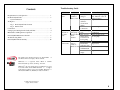
FireCaddy DC™ is shipped for the most part pre-assembled and requires only a
few connections as in the following diagrams and Connections Chart. Check to
make sure all the listen parts are included in the delivery package.
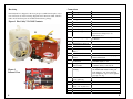
Figure 1 FireCaddy™ DC1205 Contents
21
Description
1
2
3
4
5
6
7
8
Container Box – Metal
Motor
Pump
On / Off Switch
Relay
Battery
Battery Charger
Battery Charger Cord
9
Battery Charger Plug In
10
11
12
13
Battery Disconnect
Inlet Water Connection
Strainer
¾” Polybraid Water Inlet
Hose
FlameOut® Check Valve
FlameOut® Shut Off
Valve
FlameOut® Inlet
Connection
Weight: for FlameOut®
Suction Tube
FlameOut® 3/8” Suction
Tubing
22
19
16
4
9
1
20
7
8
11
14
15
12
13
16
17
18
17
18
Figure 2
Internal View
5
6
10
19
3
15
14
4
2
20
21
22
23
FlameOut® Container:
5 US gallon jug
Outlet Connection
Fire Hose:
25 ft of ¾” lay flat hose
Valve: Nozzle (On/Off)
Nozzle: Scotty
Installation / Connection (in order)
plug into an electrical outlet
Only if not already connected
black ends to Charger (+ to +);
white end to box
plug charger wire into battery
connector
connect when all hooked up and ready
screw onto Inlet Water Connection
screw onto Strainer
turn ON (handle in-line with piping) to
induce FlameOut®
insert grey end of clear suction tubing,
pull back slightly to seal
insert hose end into FlameOut®
container entirely to the bottom
insert grey end of clear suction tubing
into FlameOut® induction inlet, pull
back slightly to seal; insert end with
brass weight into jug to bottom; tighten
grey cap onto jug
screw onto Outlet Connection
screw onto fire hose
screw onto Valve
5