1
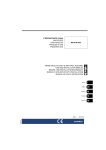
DS
LT
AGE THRES
25A In-vehicle 3-Stage
12V Battery Charger
BCDC1225-LV
OL
V
LV
H
V
LOW
LOW
O
LDS
HO
E THRE
TAG
S
OL
THE BCDC1225-LV
The BCDC1225-LV In-vehicle Battery Charger features technology designed to charge your
batteries to 100%, regardless of their type or size. By providing a unique charging profile to
each specific battery type, the BCDC1225-LV In-Vehicle Battery Charger is able to achieve and
maintain an optimal charge in your auxiliary battery, at all times. It is designed to operate with
variable voltage alternators
The BCDC1225-LV In-vehicle Battery Charger also features a Maximum Power Point Tracking
(MPPT) solar regulator, allowing you to deliver the maximum amount of power from your solar
panels to your auxiliary battery.
WARNING & SAFETY INSTRUCTIONS
This appliance is not intended for use by persons (including children) with reduced physical,
sensory or mental capabilities, or lack of experience and knowledge, unless they are supervised
or have been instructed on how to use the appliance by a person responsible for their safety.
Children should be supervised to ensure that they do not play with the appliance.
Do NOT disassemble the BCDC1225-LV - the internal circuitry contains hazardous voltages.
Attempting to service the unit yourself may result in electric shock or fire and will void the unit
warranty.
Do NOT use the BCDC1225-LV to charge non-rechargeable batteries. Doing so may result in
harm to the user and/or damage to the BCDC1225-LV. Only use the BCDC1225-LV for charging
Standard Lead Acid, Calcium content, Gel & AGM type 12V batteries.
All lead acid batteries produce harmful, explosive gases. The Battery should be mounted in a well
ventilated area, as far as possible from any ignition sources. Do NOT smoke when in the vicinity
of the battery under charge.
Battery acid is a harmful substance. Care should be taken when working with lead acid batteries,
if the acid comes into contact with your eyes or skin, immediately wash the affected area with
cold running water and seek medical assistance. Eye protection and gloves should be worn when
handling lead acid batteries.
The BCDC1225-LV will achieve best results when proper battery maintenance is regularly
performed. This includes but is not limited to checking water and specific gravity levels of the
battery.
Warning! Check the manufacturers data for your battery and ensure that the ‘Absorption’ voltage
of the profile you select does not exceed the manufacturers recommended maximum charging
voltage. If the ‘Absorption’ voltage for your battery type is too high, please select another charging
profile.
SAL.FOR.Instruction Manual.BCDC1225-LV – DOC482 – Version 3
1
CONTENTS
Table of Contents
Page
Warnings and Safety Instructions
Contents
Specifications
1 Product Function
1. Alternator Input
2. Solar Input
3. Charging Algorithm
4. Turn On/Off Thresholds
5. External LED Indication
6. Display Panel
7. Error Codes
2 Installation
1. Wiring
3 Troubleshooting
4 Frequently Asked Questions
5 Two Year Warranty
01
02
02
03
03
03
04
04
05
05
06
06
08
11
12
14
Specifications
DC Input Voltage Range
Absorption Voltage
Float Voltage
No Load Current
Standby Current
Input Fuse Rating 12V/24V
Output Fuse Rating
Output Power
Ambient Temperature
Minimum O/P Battery Volts
Weight
Dimensions
Warranty
Standards
BCDC1225-LV
9V-32V
Gel/AGM
Std Lead Acid
Calcium Content
14.5V
14.9V
15.3V
13.3V
13.3V
13.3V
<100mA
<8mA
40A/30A (Not supplied)
40A (Not supplied)
375W
-20°C to +80°C
4.2V
680g
150x120x37mm
2 years
CE, C-Tick, AS/NZS CISPR11:2004
2
1
PRODUCT FUNCTION
The BCDC1225-LV is a multi stage, 12V, 25A, DC-DC battery charger that operates from
an input of 12V nominal or a 12V nominal solar panel input. The input voltage of the
BCDC1225-LV can be above, below or equal to the output voltage making it ideal for
charging an auxiliary 12V battery where the distance from the main battery may cause a
significant voltage drop. The BCDC1225-LV is also designed to isolate the main battery
from the auxiliary battery, to avoid over-discharging the main battery and operate with
variable voltage alternators
1.1
Alternator Input
To select the Alternator charging mode the BLUE ‘Source Select’ wire must be
connected to Input Positive.
The output battery will only be charged when the alternator is running, and the
vehicle ignition is ON, guaranteeing that the charger will not drain the input battery.
1.2
Solar Input
The BCDC1225-LV is also capable of charging the auxiliary 12V battery from a
Solar source, Solar charging mode is selected at time of installation. The unit will
accept an input directly from the solar panels and act as a MPPT Solar Regulator.
To select the Solar charging mode the BLUE ‘Source Select’ wire can either be left
disconnected or connected to GROUND.
1.3
Charging Algorithm
When the BCDC1225-LV is turned on, it will move into the bulk charging stage
called Boost stage. Boost stage maintains a constant current until the battery
voltage reaches its set point. The current in Boost stage may vary during operation
in order to maintain safe operating temperature, or to limit the difference between
input and output voltage.
The charger will then move to Absorption stage. This stage maintains a constant
voltage level until the battery is full, after which the charger will enter float stage.
Float stage maintains 13.3V on the output battery, keeping the battery topped
up. This counteracts the battery’s self discharging. When a load applied to the
battery causes it to lose charge, the charger will move back into Boost.
3
1
PRODUCT FUNCTION
1.4
Turn On/Off Thresholds
12V
Solar
Low voltage conditions
(open circuit, tested every
100s)
Turn ON above 12V
Turn ON above 17.5V
Turn OFF below 11.9V
Turn OFF below 17.2V
Low voltage conditions
(loaded, constantly tested)
Turn OFF instantly below Turn OFF instantly below
8V
8V
Over voltage shutdown
Turn OFF after 20 secs
below 9V
N/A
Turn ON below 15.5V
Turn ON below 28V
Turn OFF instantly above Turn OFF instantly above
16V
29V
Turn OFF after 20 secs
above 15.6V
Under voltage shutdown
1.5
Turn OFF after 20 secs
above 28.2V
Shutdown if Output Battery < 4V
External LED Indication
A flying lead output (GREEN wire) is provided to connect an external indicator
LED, which can be mounted away from the unit, for example in the vehicle cabin.
The positive lead of the LED will be connected to the indicator output wire (flying
lead) provided, and the negative lead of the LED will be connected to the vehicle’s
ground. No external resistors are required.
The remote indicator LED will indicate charging state as described below:
LED State
Description
Off constant
Not charging
On constant
Charging or maintaining charge
4
1
PRODUCT FUNCTION
1.6
Display Panel
The BCDC1225-LV has three Battery Type Settings available. These settings
enable optimal charging profiles for the auxiliary battery. The battery type
selected is displayed via the LEDs on the front panel in the section ‘Battery Type’.
In addition to the battery type, the status of the charger is indicated via three
LEDs. The ‘Charging Status’ shows when the unit is in BOOST, ABSORPTION
or FLOAT. In order to give more information, the applicable LED will flash to
indicate the output by the unit. The longer the flash, the more current the charger
is putting out. If the LED is ON solid, then the unit is supplying a full 25A to the
auxiliary battery.
BATTERY TYPE
RoHS
Compliant
CHARGE STATUS
AGM/gel
Boost
Standard
Absorption
Calcium
Float
3 stage
battery charger
Designed and made in Australia
Figure 1.6.1 - BCDC1225-LV Front Panel
Standby mode is entered when the unit is not charging. In this mode, the Battery
Type LED will blink approx once per second; the charging status LEDs will be off.
In this mode, if the battery type wire is moved then the selected battery type will
update.
1.7
Error Codes
In the event of a fault with the unit, installation, either battery or solar panel,
both the External LED and ALL the LEDs on the unit will flash to indicate the
fault type. Flashing sequences are described in the table below.
LED State
Description
1 flash (1 flash followed by 3.5 second off)
Internal Hardware Fault
2 flash (2 flash followed by 3.5 second off)
Reserved
3 flash (3 flash followed by 3.5 second off)
Unit over temp fault
4 flash (4 flash followed by 3.5 second off)
Output Battery Fault (Volts too high)
5 flash (5 flash followed by 3.5 second off)
Input under voltage (Battery)
6 flash (6 flash followed by 3.5 second off)
Input over voltage (Battery or Solar panel)
7 flash (7 flash followed by 3.5 second off)
Reverse polarity
5
2
INSTALLATION
1
Mount the unit to a flat surface close to the auxiliary battery and away from any
heat sources.
NOTE: The unit will operate optimally below 55°C with good airflow. At higher
temperatures the unit will de-rate output current.
2
Wire into vehicle as per the applicable diagram on the next pages, and following
the steps below.
The BCDC1225-LV is connected using 6 wires, listed below:
•
•
•
•
•
•
Source Select
Battery Type
Remote Indicator
Input Battery Positive
Common Ground
Output Battery Positive
Blue
Orange
Green
Red
Black
Brown
40A/30A* Fuse (not supplied)
40A Fuse (not supplied)
* Current rating is for 24V input voltage.
1. Wire the ‘Common Ground’ wire to a ground point that is common to both the
Start battery (or the Solar Input Ground wire) and the Auxiliary battery to be
charged. This point MUST be on the chassis of the vehicle, on the chassis of the
trailer/camper/caravan, NOT directly wired to the main battery.
2. Wire the ‘Output Battery Positive’ to the Auxiliary battery positive terminal. Ideally
the BCDC unit should be a maximum of 1 metre in cable length from the battery
positive terminal, and should be wired with a minimum of 7.71mm² or 8 B&S
cable.
3. Wire the ‘Input Battery Positive’ wire to the Start battery positive terminal via a
60A N/O ignition controlled relay, or the Solar Input Positive wire, depending on
your install. Below is a table outlining the required cable size for a given cable
install length. Always choose a wire diameter equal to or greater than what is
specified below.
Cable Install Length
(m)
1-5
5-9
Minimum Wire Size
(mm²)
6
6
Recommended Wire
Size (mm²)
13.56
20.28
6
Closest (BAE, B&S,
AWG)
6
4
2
INSTALLATION
4. Wire the ‘Source Select’ wire according to your installation requirements. For a
setup charging from a 12V alternator, connect this wire to the ‘Vehicle Ignition’.
For a Solar only charging setup, connect this wire to GROUND or just leave it
disconnected. This wire is monitored at all times.
5. Wire the ‘Battery Type’ wire according to the type of Auxiliary battery you have
installed. This wire is monitored when the charger is not charging.
Connection
Battery type (Orange)
Source select (Blue)
12V Input positive
ca
Calcium
Alternator charge
Ground
pb
Standard Lead Acid
Solar charge
Not connected
gl
AGM or Gel
Solar charge
N
C
NOTE: The unit will operate optimally below 55°C with good airflow. At higher
temperatures the unit will de-rate output current.
IMPORTANT NOTE: Battery type selection refers to a typical installation where the
battery and unit are mounted in a low to mid temperature situation. For situations
of higher temperature such as under the bonnet or in a caravan battery box, a softer
profile (eg Std Lead Acid instead of Calcium) may need to be selected to avoid damage
to the battery.
7
2
INSTALLATION
2.1
Wiring
The heavy gauge wires on the BCDC1225-LV unit carry peak currents of up to 35
Amps, and it is important to make a good, low resistance, electrical connection
that will not degrade over time. Failure to make a good, reliable contact may
result in breakdown of the wire insulation and cause a short circuit, or worst case
a fire. We recommend that this activity be undertaken by an appropriately trained
person.
Redarc recommends using a soldered butt splice crimp connection that is covered
with heatshrink. The process should be to feed the heatshrink over the wires,
crimp the wires into the butt splice, then solder the wires on the butt splice, and
finally heat the heatshrink. Do not solder the wire before crimping.
Redarc does not recommend using standard red/ blue/yellow blade connections
as they are not rated for either the current or gauge of wire supplied on the unit.
The appropriate sized butt splice should be selected: for example if 8AWG wires
are used to connect the unit then an 8AWG butt splice should be used. If the wire
gauge brought up to the unit is larger than the 8AWG, then it is recommended to
use a butt splice that has two different size entrys, each matching the respective
wire size. Various butt splices are available from auto electrical suppliers.
Crimping provides good mechanical connection, soldering provides a long lasting
electrical connection and forming of the heatshrink will prevent any shorting/
contact with your vehicle chassis.
The term ‘crimping’ refers to a method of firmly attaching a terminal or contact
to the end of an electrical conductor by pressure forming or reshaping a metal
barrel onto the connector. The forming of a satisfactory crimp is dependent upon
the correct combination of conductor, crimp barrel and crimping tool. When
the correct combination of equipment is employed, a crimp that has both good
electrical and mechanical characteristics will be formed.
Butt splices are used to dress and terminate multiple conductors of the same or
different gauges in an end-to-end or series configuration.
8
2
INSTALLATION
Crimp here.
Slip heatshrink over wire and insert wires into
butt splice. Keep heatshrink away from joint until
after soldering is complete and has cooled.
Crimp both wires to the butt splice using indent
type crimpers.
Solder here.
Wait for the butt splice to cool, slip heatshrink
over the joint and heat.
Solder the wires to the butt splice. Ensure that a
good connection is made.
Figure 2.1 - Ensuring a good wiring connection
12V
INPUT
SOLAR
INPUT
40A
Fuse
12V Solar Panel
Array
12V Changeover
Relay (60A)
to vehicle
ignition
Start
Battery
Note: Power wires must be
at least 6mm² and must be
crimped using an
appropriate crimp tool.
Battery
config
wire
40A
Fuse
All ground points must
be connected to chassis
earth.
Figure 2.2 - Standard setup for a 12V Start Battery & 12V Solar Array
9
Load
Fuse
Loads
Auxiliary
Battery
2
INSTALLATION
12V
INPUT
40A
Fuse
To vehicle ignition
Note: Power wires must be
at least 6mm² and must be
crimped using an
appropriate crimp tool.
Start
Battery
Battery
config
wire
40A
Fuse
Load
Fuse
All ground points must
be connected to chassis
earth.
Loads
Auxiliary
Battery
Figure 2.3 - Standard setup for a 12V Start Battery
SOLAR
INPUT
12 Solar Panel
Array
Battery
config
wire
Note: Power wires must be
at least 6mm² and must be
crimped using an
appropriate crimp tool.
All ground points must
be connected to chassis
earth.
Figure 2.4 - Standard setup for a 12V Solar array
10
40A
Fuse
Load
Fuse
Loads
Auxiliary
Battery
3
TROUBLESHOOTING
Start and run engine
for 30 seconds - leave
engine running whilst
troubleshooting.
Is the
correct ‘Battery Type’
LED on solid or
flashing?
Shutdown the
vehicle and rectify
the problem.
Check the ORANGE
wire. Is it installed as per
the instructions and correct
for your battery type?
No
Yes
Is the
‘Charge Status’ light
flashing in one of the
three stages?
Yes
Check the RED
wire. Is it installed with
appropriate gauge wire and
connected to the source
you require?
No
Yes
No
Yes
Check
the BLUE wire.
BATTERY - BLUE to IGNITION
SOLAR - BLUE to GROUND or
NO CONNECT is the BLUE
wire setup like
this?
If an External LED
is fitted, is it working as
described on page 5
No of this manual?
Check the connection
to the BCDC, and the
orientation of the LED as per
the install diagrams. If the problem
is still evident contact a qualified
Auto Electrician, or Redarc
Electronics.
No
Yes
No
Yes
Are all
battery negative wires,
solar negative wire and BLACK
BCDC wire connected to a
common ground point?
(chassis)
The BCDC is operating correctly. If a low
auxiliary battery voltage occurs - check
BROWN wire is making a good
connection to the auxiliary battery. If the
problem is still evident, get a qualified
Auto Electrician to inspect the system.
No
Yes
Is the input
voltage above 13.2V
for a 12V system
or 17.5V for a
solar setup?
Check that the alternator
is charging properly. If
the problem is still evident
contact a qualified Auto
Electrician or Redarc
Electronics.
No
Yes
The BCDC is not operating
correctly. Have a qualified
Auto Electrician check the wiring,
fuses, batteries and charging
system or contact Redarc
Electronics for more information.
Yes
Is the auxiliary
battery voltage
above 4V?
No
Remove all loads from the
auxiliary battery and charge it
overnight, using a multi-stage charger
and then recheck the battery.
If the battery voltage is
still low, replace battery.
Figure 3.1 - Standard BCDC1225-LV Troubleshooting Guide
11
4
FREQUENTLY ASKED QUESTIONS
Q
A
The BCDC turns ON at 12.0V and OFF at 11.9V, but you say it operates down to 9V, explain?
The BCDC will turn OFF for a split second every 100 seconds to measure the unloaded voltage at the
battery. When the BCDC turns off it is not drawing any load from the start battery, no load means
that there is no voltage drop over the cable run. This allows the BCDC to measure the actual battery
voltage, or the voltage at the battery. If this actual battery voltage is below 11.9V, the BCDC will
turn OFF. At any other time during the charging process, if the voltage at the BCDC drops below 9V
the BCDC will turn OFF.
Q
A
How does the BCDC charge an Auxiliary battery at 14V when it only gets 9V in?
The BCDC can act as both a reducer and a booster, so it can operate from a voltage of above, equal
to or below the desired output voltage. The unit is also microprocessor controlled allowing it to
output a Redarc proprietary charging algorithm independent of the input. This allows the unit to
charge specific to the battery type even if the input voltage is low due to voltage drop.
Q
A
Where should I mount the BCDC Unit?
The BCDC should be mounted as close as possible to the battery being charged (generally called the
Auxiliary or House battery). If the Auxiliary battery is located under the bonnet, pick a location for the
BCDC that is close to the battery and away from any direct engine heat. If the BCDC is to be mounted
into a Caravan or Camper, near or in the battery compartment is generally the best position. It is also
a good idea to mount the BCDC to a metal surface if possible to ensure optimal heat dissipation,
though this is not crucial.
Q
A
What does the charger do if the temperature around it rises above its operating temperature?
As the temperature of the BCDC rises above a certain level the current capacity of the output is
decreased gradually in order protect both the battery and the BCDC unit.
Q
A
If I use the BCDC to charge my auxiliary battery do I still need to install a battery isolator?
The BCDC incorporates the functionality of a battery isolator, it will turn ON and start charging when
it senses that the vehicle has started and similarly it will turn OFF when the vehicle is turned OFF.
Q
I’ve heard that you shouldn’t charge 2 batteries of different chemistries from the same source,
will I have any problems charging my AGM or Gel auxiliary battery from my Lead Acid start
battery?
The BCDC does not ‘link’ the batteries together like a battery isolator does, it is a DC-DC battery
charger. The output from the unit is tailored specifically to the selected output battery type, and
therefore allows the optimal charging of the auxiliary battery, no matter what chemistry your start
battery is.
A
Q
A
My BCDC is setup for 12V Alternator input but will not start when the vehicle is turned On, I’ve
followed the trouble shooting guide and the setup is fine, what’s the problem?
The most likely cause of this issue is that the BCDC is somehow ‘stuck’ in 24V mode. Try removing
the ‘Source Select’ (Blue) wire and reconnecting it. If the problem still exists please contact Redarc
Electronics.
12
13
5
TWO YEAR PRODUCT WARRANTY
Over the last three decades our company has established a reputation as the power conversion specialist.
A 100% Australian-owned company, we have met the needs of customers in transport and other industries through exciting, innovative thinking.
We believe in total customer satisfaction and practice this by offering our customers:
•
Technical advice free of jargon and free of charge
•
Prompt turnaround of orders throughout Australia and globally
•
Friendly, personalised, professional service and product support
In the unlikely event that a technical issue arises with a Redarc product, customers are encouraged to initially contact the Redarc Technical Support Team on (08) 8322 4848
or [email protected] for prompt and efficient diagnosis and product support.
Our goods come with guarantees that cannot be excluded under the Australian Consumer Law. You are entitled to a replacement or refund for a major failure and compensation for
any other reasonably foreseeable loss or damage. You are also entitled to have the goods repaired or replaced if the goods fail to be of acceptable quality and the failure does not
amount to a major failure.
The benefits of this Warranty are in addition to other rights and remedies available at law in respect of the Products and shall not derogate from any applicable mandatory statutory
provisions or rights under the Australian Consumer Law.
Redarc Electronics Pty Ltd atf the Redarc Trust trading as Redarc Electronics (“Redarc
(“Redarc”)
”) offers a warranty in respect of its Products where the Products are purchased from an
authorised distributor or reseller of Redarc by a person (“Purchaser
(“Purchaser”),
”), on the terms and conditions, and for the duration, outlined below in this document (“Warranty
(“Warranty”).
”).
1. In this Warranty, the term Products means:
1.1 all products manufactured or supplied by Redarc (excluding its solar products
which are covered by Redarc’s Solar Product Warranty); and
1.2 any component of or accessory for any product in clause 1.1 manufactured or
supplied by Redarc.
Offer and duration of product warranties
2. Redarc warrants that its Products will be free, under normal application, installation,
use and service conditions, from defects in materials and workmanship affecting
normal use, for 2 years from the date of purchase (Warranty Period).
3. Where a Product malfunctions or becomes inoperative during the Warranty Period,
due to a defect in materials or workmanship, as determined by Redarc, then subject
to further rights conferred by the Australian Consumer Law on the Purchaser,
Redarc will, in exercise of its sole discretion, either:
3.1 repair the defective Product;
3.2 replace the defective Product; or
3.3 provide a refund to the Purchaser for the purchase price paid for the defective
Product,
without charge to the Purchaser.
4. The warranty given by Redarc in clause 3 covers the reasonable costs of delivery
and installation of any repaired or replaced Products or components of Products
to the Purchaser’s usual residential address notified to Redarc, together with the
reasonable costs of removal and return of any Products determined by Redarc to be
defective.
5. If the Purchaser incurs expenses of the nature referred to in clause 4 in the
context of making a claim pursuant to this Warranty that is accepted by Redarc,
the Purchaser will be entitled to claim for reimbursement of those expenses which
Redarc determines, in exercise of its sole discretion, to be reasonably incurred,
provided that the claim is notified to Redarc in writing at the postal address or email
address specified in clause 21 and includes:
5.1 details of the relevant expenses incurred by the Purchaser; and
5.2 proof of the relevant expenses having been incurred by the Purchaser.
Exclusions and limitations
6. This Warranty will not apply to, or include any defect, damage, fault, failure
or malfunction of a Product, which Redarc determines, in exercise of its sole
discretion, to be due to:
6.1 normal wear and tear or exposure to weather conditions over time;
6.2 accident, misuse, abuse, negligence, vandalism, alteration or modification;
6.3 non-observance of any of the instructions supplied by Redarc, including
instructions concerning installation, configuring, connecting, commissioning,
use or application of the Product, including without limitation choice of location;
6.4 failure to ensure proper maintenance of the Product strictly in accordance with
Redarc’s instructions or failure to ensure proper maintenance of any associated
equipment or machinery;
6.5 repairs to the Product that are not strictly in accordance with Redarc’s
instructions;
6.6 installation, repairs or maintenance of the Product by, or under the supervision
of, a person who is not a qualified auto electrician or technician, or if nongenuine or non-approved parts have been fitted;
6.7 faulty power supply, power failure, electrical spikes or surges, lightning, flood,
storm, hail, extreme heat, fire or other occurrence outside the control of
Redarc;
6.8 use other than for any reasonable purpose for which the Product was
manufactured;
6.9 any indirect or incidental damage of whatever nature outside the control of
Redarc.
7. Warranty claims in respect of a Product must be made in writing to Redarc at the
postal address or email address specified in clause 21 within the Warranty Period.
Such claims must include the following:
7.1 details of the alleged defect or fault and the circumstances surrounding the
defect or fault;
7.2 evidence of the claim, including photographs of the Product (where the subject
of the claim is capable of being photographed);
7.3 the serial number of the Product, specified on the label affixed to the Product;
and
7.4 proof of purchase documentation for the Product from an authorised distributor
or reseller of Redarc, which clearly shows the date and place of purchase.
The return of any Products without the prior written instructions of Redarc will not
be accepted by Redarc.
8. Without limiting any other clause in this Warranty, Redarc has the right to reject any
Warranty claim made by a Purchaser pursuant to this Warranty where:
8.1 the Purchaser does not notify Redarc in writing of a Warranty claim within the
Warranty Period;
8.2 the Purchaser does not notify Redarc in writing of a Warranty claim within 1
month of becoming aware of the relevant circumstances giving rise to the
claim, so that any further problems with the Product are minimised;
8.3 the serial number of the Product has been altered, removed or made illegible
without the written authority of Redarc;
8.4 the Purchaser is unable to provide proof of purchase documentation in
accordance with clause 7.4 or evidence that the Product was properly installed
and removed (if relevant), and that proper maintenance has been performed
on the Product, by, or under the supervision of, a qualified auto electrician or
technician, in accordance with the instructions of Redarc.
9. If the Product is found to be working satisfactorily on return to Redarc or upon
investigation by Redarc, the Purchaser must pay Redarc’s reasonable costs of
testing and investigating the Product in addition to shipping and transportation
charges. Where Redarc is in possession of the Product, the Product will be
returned to the Purchaser on receipt of the amount charged.
10. Any replaced Products or components of Products shall become the property of
Redarc.
11. Redarc may, in exercise of its sole discretion, deliver another type of Product or
component of a Product (different in size, colour, shape, weight, brand and/or
other specifications) in fulfilling its obligations under this Warranty, in the event
that Redarc has discontinued manufacturing or supplying the relevant Product or
component at the time of the Warranty claim, or where such Product or component
is superior to that originally purchased by the Purchaser.
Other conditions of Warranty
12. If the Purchaser acquired a Product for the purpose of resupply, then this Warranty
shall not apply to that Product.
13. In particular, the sale of a Product via an online auction, online store or other
internet website by a party that is not an authorised distributor or reseller of the
Product will be deemed to be a resupply within the meaning of the Australian
Consumer Law and will render this Warranty void, as Redarc has no control over the
storage, handling, quality or safety of Products sold by such persons.
14. A Purchaser shall only be entitled to the benefit of this Warranty after all amounts
owing in respect of the Product have been paid.
15. While Redarc warrants that the Products will be free from defects in materials and
workmanship in the circumstances set out in this Warranty, to the maximum extent
permitted by law Redarc does not warrant that the operation of the Products will be
uninterrupted or error-free.
16. To the maximum extent permitted by law, Redarc’s determination of the existence of
any defect and the cause of any defect will be conclusive.
17. Spare parts or materials for the Products are guaranteed to be available for a period
of at least 2 years after purchase of the Products.
18. The agents, officers and employees of any distributor or reseller of the Products and
of Redarc are not authorised to vary or extend the terms of this Warranty.
19. Redarc shall not be responsible or liable to the Customer or any third party in
connection with any non-performance or delay in performance of any terms and
conditions of this Warranty, due to acts of God, war, riots, strikes, warlike conditions,
plague or other epidemic, fire, flood, blizzard, hurricane, changes of public policies,
terrorism and other events which are beyond the control of Redarc. In such
circumstances, Redarc may suspend performance of this Warranty without liability
for the period of the delay reasonably attributable to such causes.
20. If a clause or part of a clause in this Warranty can be read in a way that makes it
illegal, unenforceable or invalid, but can also be read in a way that makes it legal,
enforceable and valid, it must be read in the latter way. If any clause or part of
a clause in this Warranty is illegal, unenforceable or invalid, that clause or part is
to be treated as removed from this Warranty, but the rest of this Warranty is not
affected.
Redarc’s contact details
21. Redarc’s contact details for the sending of Warranty claims under this Warranty are:
Redarc Electronics Pty Ltd
23 Brodie Road (North), Lonsdale SA 5160
Email: [email protected]
Telephone: +61 8 8322 4848
14
Free technical assistance!
please contact
Redarc Electronics
23 Brodie Road North, Lonsdale SA
(08) 8322 4848
[email protected]
www.redarc.com.au
Copyright © 2012 Redarc Electronics Pty Ltd. All rights reserved.
WARBCDC1225-LV - REV3
www.redarc.com.au